

DCS ADR130 Installation Manual
THE PROFESSIONAL ACCESS DRAWERS
Installation Guide
MODELS:
ADR48 ADR30
ADR36 ADR24

A MESSAGE TO OUR CUSTOMERS
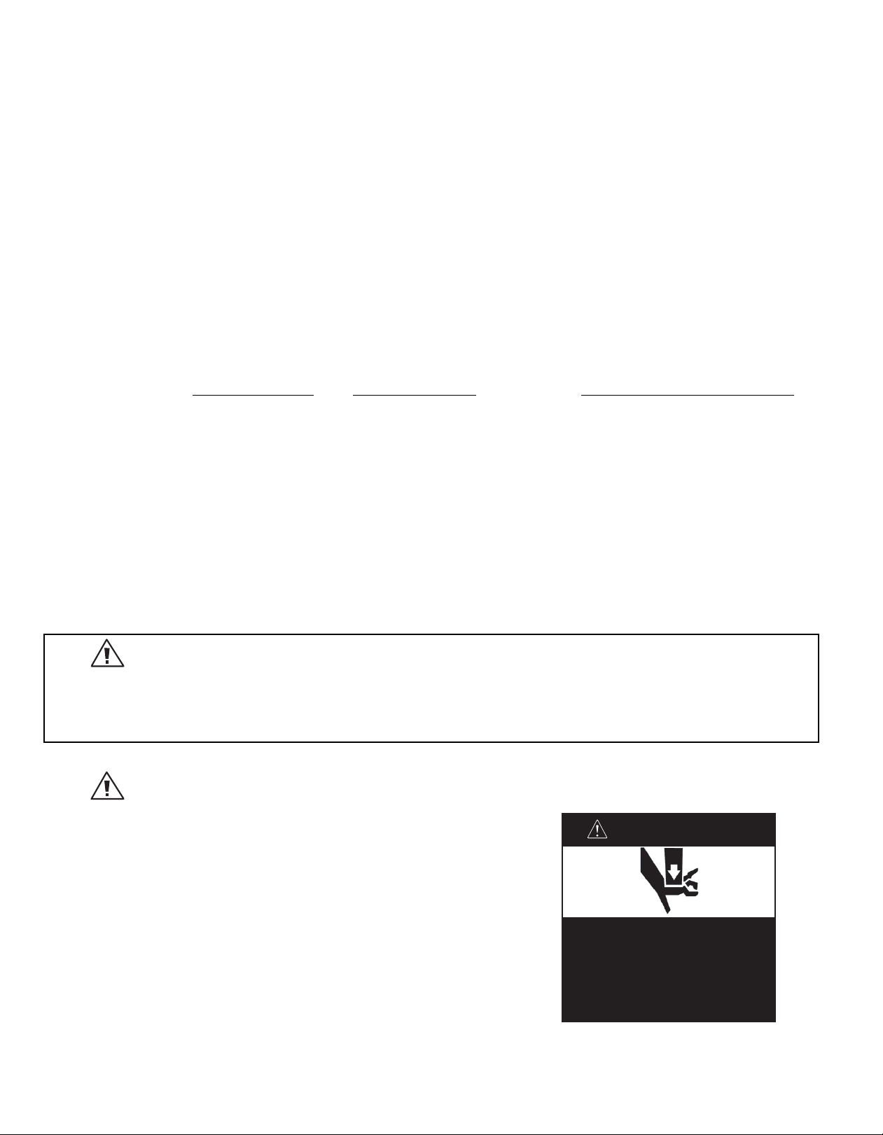
• Closing drawers may cause injury to
your hands or fingers.
• Always close or open drawers using
their handles.
• Be sure to keep hands away from
drawer edges when opening or
closing drawers.
WARNING
Thank you for selecting these DCS by Fisher & Paykel Professional Access Drawers. Because of this product’s
unique features we have developed this Installation Guide. It contains valuable information on how to properly
install and maintain your new Professional Access Drawers for years of safe and enjoyable use.
To help serve you better, please fill out and submit your Product Registration by visiting our website at
www.dcsappliances.com and selecting “Customer Care” on the home page and then select “Product
Registration”. In addition, keep this guide handy, as it will help answer questions that may arise as you use your
new Access Drawers.
For your convenience, product questions can be answered by a DCS by Fisher & Paykel Customer Care Representative by phone at 1-888-936-7872, or email: customer.care@fisherpaykel.com.
NOTE: Please write the Model, Code, and Serial Numbers on this page for references (located on the inside, top
right of the back wall. See Fig. 02.)
MODEL NUMBER CODE SERIAL NUMBER
NOTE: Inspect the product to verify that there is no shipping damage. If any damage is detected, call the shipper
and initiate a damage claim. DCS by Fisher & Paykel is not responsible for shipping damage.
DO NOT discard any packing material (box, pallet, straps) until the unit has been inspected.
WARNING
Do Not store or use gasoline or other flammable vapors and liquids inside or in the vicinity of this or any other
1
.
appliance.
2.
An LP cylinder not connected for use shall not be stored inside or in the vicinity of this unit.
FOR YOUR SAFETY
1
. Do not allow children or pets to play in or around the Access Drawers.
2
. Clean the Access Drawers regularly using a mild dish washing liquid and
3
. To maintain the exterior appearance, apply a stainless steel polish to the
4
. Sanitize the Access Drawers surfaces each season as necessary.
5
. To prevent the formation of mold or mildew, do not store cloth napkins
6
. Cooking utensils that are stored in the Access Drawers should be stored
7
. To prevent personal injur
.
er
t
a
w
outside surfaces on a regular basis.
or tablecloths in the Access Drawers for long periods.
in sealable plastic bags and/or w
ashed each time bef
y or damage to the drawers, do not overload
them. The maximum rating per drawer is 75 pounds.
or
e r
-use.
e
1

TABLE OF CONTENTS
SAFETY PRACTICES & PRECAUTIONS 2
MODEL IDENTIFICATION & DIMENSIONS 3
HIPPING INSPECTION 3
S
INSTALLATION
Make Cutout and Installing Support Structure 4
Removing Drawers 5
Slide in Access Drawers and Mount to Support Structure 5
Re-installing Drawers 6-7
CARE & MAINTENANCE 8
WARRANTY 9-10
SAFETY PRACTICES AND PRECAUTIONS
1. Begin by insuring proper installation and servicing.
2. Follow the installation instructions in this manual.
tend the service life of your product, be sure to follow the use and care guidelines in this manual.
o ex
T
3.
WARNING:
Do not store items of interest to children above or on the inside of any appliance. Children could be seriously injured
o or into the appliance to reach these items.
if they should climb on
t
2

MODEL IDENTIFICATION & DIMENSIONS
F
D
H
W
DIMENSIONS
Fig. 1
SHIPPING INSPECTION
1. Inspect the Access Drawers to verify that there is no
shipping damage.
f any damage is detected, call the shipper and initiate
I
2.
a damage claim. DCS by Fisher & Paykel is not
responsible for shipping damage.
TE: Do not discard any packing material (box, pallet,
NO
straps) until the unit has been inspected.
MODEL D W H F
ADR48 24-1/4” 48” 22” 1-1/2”
ADR36 24-1/4” 36” 22” 1-1/2”
ADR30 24-1/4” 30” 22” 1-1/2”
ADR24 24-1/4” 24” 22” 1-1/2”
Fig. 1a
model and serial
number tag
■ Operate the drawers to be sure they glide smoothly.
o be sure there are no
ts t
on
er fr
w
■ Examine the dr
dents or scrat
a
ches
.
Fig. 2
3
INSTALLATION
A
90º
B
C
Vent*
Vent*
V
ent*
O
ptimal support
locations
C
B
A
8-3/4”
8-3/4”
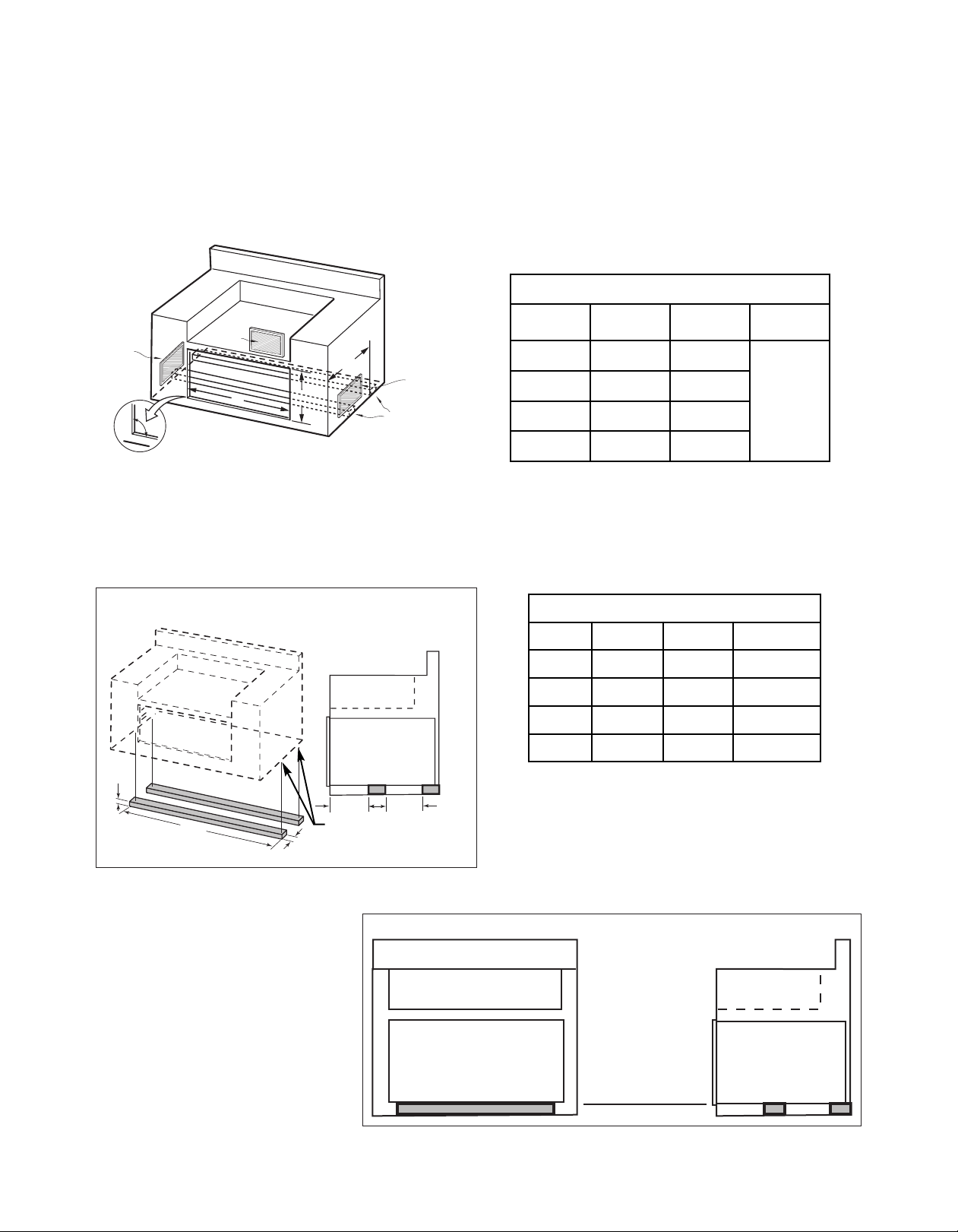
MAKE CUTOUT AND INSTALL SUPPORT STRUCTURE
1. Make a cut-out in your cabinet or island with the following dimensions (Fig. 3):
Note:
The cutout of each corner should be 90º for the Access Drawers to fit properly.
CUTOUT DIMENSIONS
MODEL
ADR48 46” 20”
(+0,-1/8)B(+1/8,-0)
A
C
ADR36 34” 20”
ADR30 28” 20”
24-1/2” min.
(all models)
ADR24 22” 20”
* Island installation to use minimum of 3 vents
providing 10 sq. in. per vent (typical).
Fig. 3
2. Place 2 X 4s to provide support for the Access Drawers structure in the locations indicated in the figure below
(Fig. 4).
3. Board lengths are provided in the table below (Fig. 5).
To ensure proper drawer operation, be sure your
support boards are flat & level.
SUPPORT BOARD DIMENSIONS
MODEL A B C
48” 44” 1-1/2” 3-1/2”* min.
36” 32” 1-1/2” 3-1/2”* min.
30” 26” 1-1/2” 3-1/2”* min.
24” 20” 1-1/2” 3-1/2”* min.
*Dependent on application.
Optimal support locations.
. 4
ig
F
Front View (typical) End View (typical)
Fig. 5
4. When installing your support boards,
be sure they are level.
5. Check to be certain that the top
edges of your boards are level with
the bottom edge of the cut-out
(Fig. 6).
Support Board (typical)
4
For proper support &
drawer operation, insure
that support boards are
level front to back & side
to side.
Fig. 6
Suppor
t B
oar
ds (t
ypical)
INSTALLATION
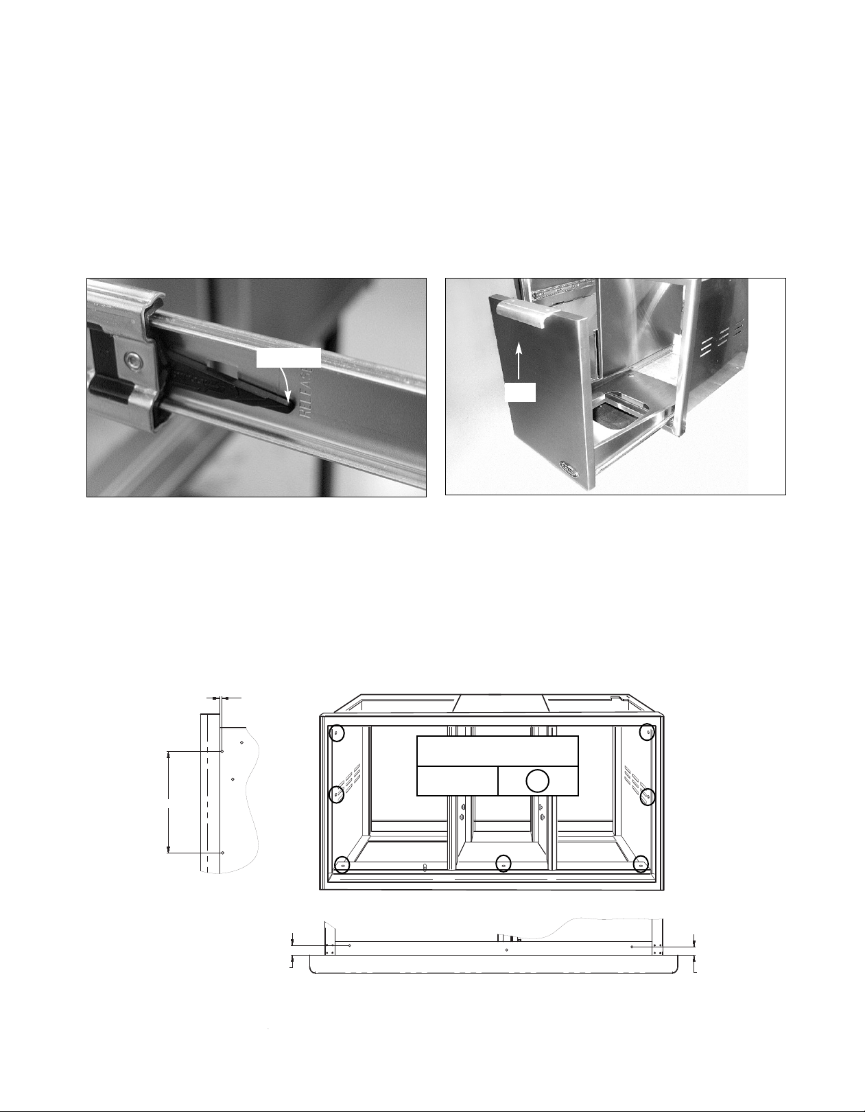
3/16"
TO 1/2"
8"
VIEW SHOWING HOLES ON
LEFT AND RIGHT SIDES
AVAILABLE FOR MOUNTING
3/4"
3/4"
VIEW SHOWING HOLES ON TOP AND BOTTOM
OF FRAME AVAILABLE FOR ADDITIONAL SUPPORT
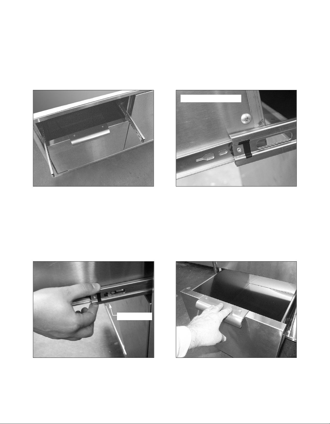
REMOVING DRAWERS
1. Once the unit has been inspected, remove the left drawers by pulling them out until their slider latch is visible.
arefully push the latch down on the left side while pulling up on the right side and pull the drawers completely
C
out of the frame (Fig. 7).
. To remove the LP tank drawer on the right, pull the drawer out and lift the end by the handle to disengage the
2
rollers (Fig. 8).
3. To prevent damage to surfaces, place the drawers on a stable surface on a protective towel or tablecloth.
Slider latch
Lift
Fig. 7
Fig. 8
SLIDE IN FRAME AND MOUNT TO SUPPORT STRUCTURE
1. With the help of an assistant, lift the unit off of the pallet and slide it into the cabinet cutout. Adjust for level and
fit.
2 Locate mounting holes on the frame (Fig. 9 and views). Secure the unit using screws suited for the type of
cabinet material.
NOTE: Depending on the wall thickness and location of mounting holes, an additional board may be required to properly
receive the screws.
MOUNTING SCREWS
(not provided)
ATIONS
OC
L
Fig. 9
5
INSTALLATION
RE-INSTALLING DRAWERS
1. Re-install the drawers by extending their guides as shown in fig. 10.
2. While holding the drawer parallel to the cabinet, carefully align & engage the ends of the glides. Slide the drawer
about an inch so that the glides are supporting the back of the drawer (Fig. 11).
Drawer Glide properly Engaged.
Fig. 10 Fig. 11
3. While holding the drawer up by the handle, pull the glides from the drawer cavity out over the drawer glide until
they click (Fig. 12).
4. As you push the drawers in, you will encounter moderate resistance. Continue to push the drawer all the way in
to complete the engagement process. The drawer will now glide smoothly in & out with light effort (Fig. 13).
Drawer Cavity Glide
Fig. 12
Fig. 13
6
INSTALLATION
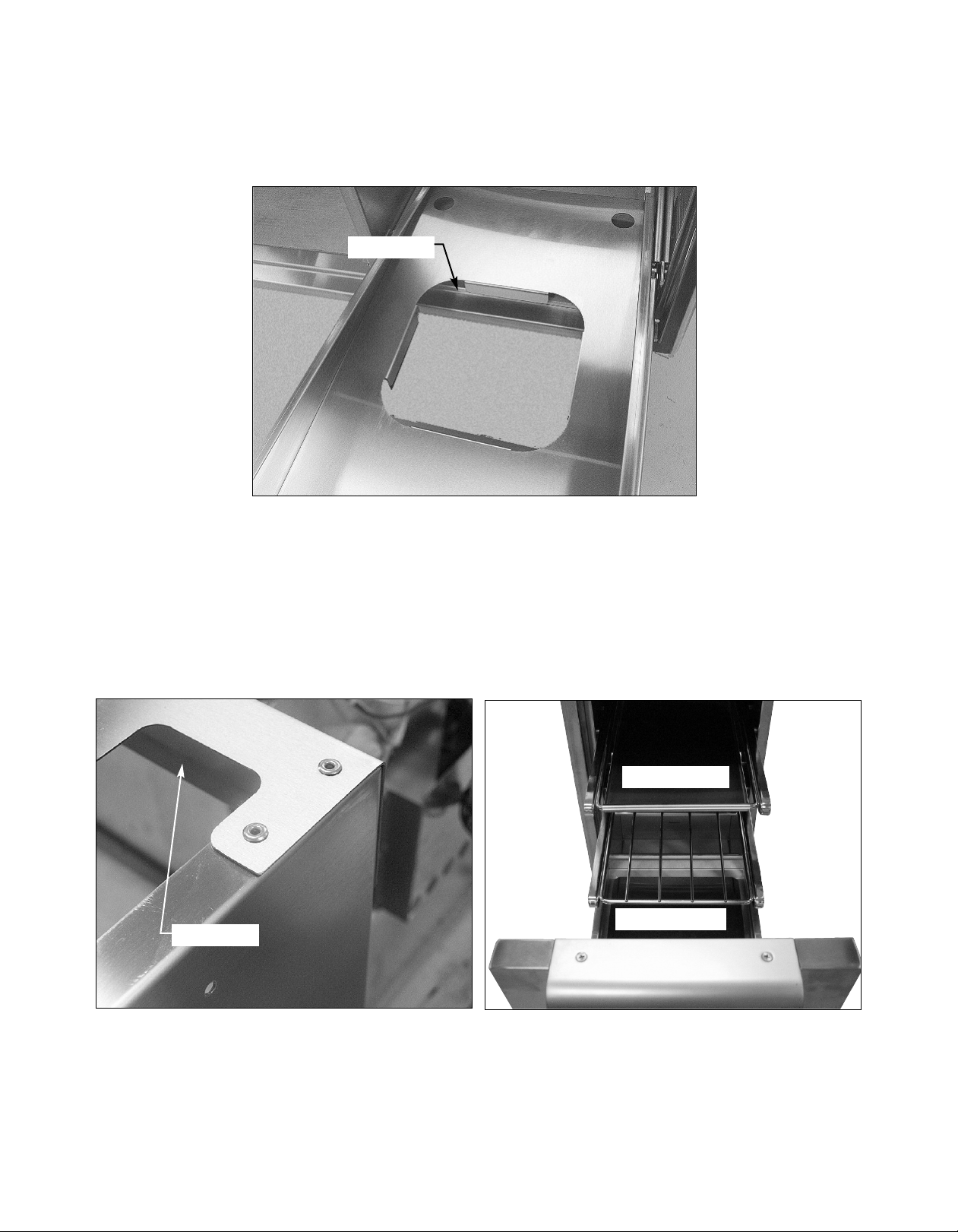
6. Your LP tank will be installed in the recess provided in the bottom of the right compartment (Fig. 14).
Tank Receptacle
Fig. 14
7. When connecting the LP tank to the gas line be certain that the gas pipe is routed through the recess provided
on the top of the right side (Fig. 15). Do not route the gas pipe through the opening in the back of the Access
Drawers. Once gas connections are made, test for gas leaks.
8. On models so equipped, install the two (2) racks provided into the opening by sliding them onto the rollers on
the sidewalls of the center cavity (Fig. 16).
Rack & Rack Cover
Drain drawer
Gas Pipe Recess
Fig. 15
. 16
ig
F
7
 Loading...