

Page 1

© 1994, 1996, 2000 dCS Ltd
All rights reserved. Reproduction of this manual in any manner whatsoever,
without the written permission of dCS1 is strictly forbidden. Additional copies of
this manual may be obtained from dCS.
Information contained in this manual is subject to change without notice, and
whilst it is checked for accuracy, no liabilities can be accepted for errors.
1
dCS Ltd is Data Conversion Systems Ltd. Company registered in the England no. 2072115
dCS 900E / 902E
Analogue to Digital Converter
User Manual
Software versions 1.3x to 1.5x
12th June 2000
Page 2

dCS 900E / 902E User Manual Manual for Software Versions 1.3x to 1.5x
dCS Ltd 12th June 2000
Manual part no: DOC0029021E1 Page 2 Document No: OS-MA-D0002-902.1E1
Contact dCS on + 44 1799 531 999 email to: [email protected]
(inside the UK replace + 44 with 0) web site: www.dcsltd.co.uk
Page 3

dCS 900E / 902E User Manual Manual for Software Versions 1.3x to 1.5x
dCS Ltd 12th June 2000
Manual part no: DOC0029021E1 Page 3 Document No: OS-MA-D0002-902.1E1
Contact dCS on + 44 1799 531 999 email to: [email protected]
(inside the UK replace + 44 with 0) web site: www.dcsltd.co.uk
PRODUCT FEATURES
Formats -
PCM at 32, 44.1 or 48 kS/s.
dCS 902E only: PCM at 88.2 or 96 kS/s.
Data formats supported are: AES/EBU (XLR), SPDIF (RCA Phono), SPDIF
optical (Toslink) and SDIF-2 (BNC).
dCS 902E only: Dual AES (XLR)
Syncing -
Master mode or can sync to Word Clock or AES reference.
Sync to video option available
Functions -
Very high performance ADC, free from gain ranging
Multichannel Sync capability
Noise shaping truncation (1st, 3rd, 9th order)
Test Generator -
High quality (160 dB) tone generator. Can be noise shaped truncated.
dCS 902E only: Variable tone frequency and level.
Ease of Use -
Remembers last settings
Lockouts
Software upgrade-able without opening the box
Can be remote controlled from PC
Page 4

dCS 900E / 902E User Manual Manual for Software Versions 1.3x to 1.5x
dCS Ltd 12th June 2000
Manual part no: DOC0029021E1 Page 4 Document No: OS-MA-D0002-902.1E1
Contact dCS on + 44 1799 531 999 email to: [email protected]
(inside the UK replace + 44 with 0) web site: www.dcsltd.co.uk
CONTENTS
Product Features................................................................................................3
CONTENTS ......................................................................................................... 4
About this Manual 5
Warranty 5
Using Your dCS 900 / 902 For The First Time................................................... 6
Product Overview 6
What’s in the Box? 6
Mains Voltages 6
Installing Unit in a Rack 6
Getting Started 8
The Hardware – Controls and Connectors....................................................10
Rear Panel 10
Front Panel 12
The Software – the Menu.................................................................................18
Overview 18
The Menu Sequence 19
Menu Items 20
Typical Applications ........................................................................................24
Six Channel Set Up Sync’ed to AES Reference 24
Six Channel Set Up Sync’ed to Master Clock (AES) 25
Six Channel Set Up Sync’ed to Word Clock 26
Six Channel Set Up Sync’ed to Master Clock (Word Clock) 27
Operating Several Units on One Remote Chain 28
Recording Dual AES on a 4-Track Recorder 29
dCS 900 / 902 Technical Information................................................................30
Anti Alias Filtering 30
Clocking 31
Sample Alignment 32
Noise Shaping 36
Digital Interface Specifications 39
Analogue Input Specifications 41
AES3 (AES/EBU) Format 42
SPDIF 45
SDIF-2 46
Power Consumption 48
Size, Weight and Operating Conditions 49
General Technical Information .......................................................................50
Word Length Reduction 50
Options..............................................................................................................54
Maintenance and Support...............................................................................56
Hardware 56
Software 57
Hardware Update or Calibration 57
Safety and Electrical Safety 57
TroubleShooting ..............................................................................................58
Error Codes and Messages 58
Internal Device Error Codes 58
System Messages and Error Codes 59
Trouble Shooting Your System 59
dCS Support ......................................................................................................61
Page 5

dCS 900E / 902E User Manual Manual for Software Versions 1.3x to 1.5x
dCS Ltd 12th June 2000
Manual part no: DOC0029021E1 Page 5 Document No: OS-MA-D0002-902.1E1
Contact dCS on + 44 1799 531 999 email to: [email protected]
(inside the UK replace + 44 with 0) web site: www.dcsltd.co.uk
I wish .... 61
If You Need More Help 61
Other Information 61
Indexes and Software Version Numbers .......................................................62
About this Manual
Note that there is a fuller Contents at the end of the manual (page 63), along
with an index and lists of figures and tables.
References to other sections in the text have the "Section Name” page … in
quotation marks and bolded.
IMPORTANT! Important information is presented like this - ignoring this may cause you to
damage the unit, or invalidate the warranty.
The manual is designed to be helpful. If there are points you feel we could cover
better, or that we have missed out - please tell us.
Warranty
Your dCS 900 or dCS 902 is guaranteed for a period of 12 months against faulty
workmanship or materials. Warranty repairs should only be carried out by dCS or
an authorised distributor. This warranty will be invalidated if the unit is misused
or tampered with in any way.
Page 6

dCS 900E / 902E User Manual Manual for Software Versions 1.3x to 1.5x
dCS Ltd 12th June 2000
Manual part no: DOC0029021E1 Page 6 Document No: OS-MA-D0002-902.1E1
Contact dCS on + 44 1799 531 999 email to: [email protected]
(inside the UK replace + 44 with 0) web site: www.dcsltd.co.uk
USING YOUR dCS 900 / 902 FOR THE FIRST TIME
Product Overview
The dCS 900 and 902 ADCs (Analogue to Digital Converters) are high
performance converters designed for studio and live recording applications.
They are designed to produce very high standard digital output that may be used
directly or archived. AES3, SPDIF and SDIF-2 PCM formats are all supported.
Multiple units may be slaved together for stable multi-channel operation.
The unit is mains powered and is housed in a 1U (1.75”) high 19” rack mounting
case. It may be controlled either from its front panel, or from a software based
remote control running on a PC. The last setting is automatically stored on
power down, so that fixed installations may be set up at leisure, installed and
then left alone. Unauthorised alterations to settings may be prevented by a
“panel lockout” feature.
The unit is highly software based, and more functions and features are added
from time to time. Software updates from dCS are free!
2
What’s in the Box?
The contents of the box are at least:
dCS 900 or dCS 902
User Manual
Function Menu Guide
Mains Lead
2 Spare Fuses
Remote cable
Remote software
Mains Voltages
The dCS 900 / 902 is shipped with its mains voltage preset for operation in the
destination country. The voltage is not intended to be changed by the user. If it
needs to be changed, contact your dealer or dCS.
Installing Unit in a Rack
The unit is supplied with 19" rack mount ears fitted. If it is to be installed in a 19"
rack, the ears supplied may be used to locate it in the rack - but:
IMPORTANT! The ears should not be used as the only mechanical support. The unit should
rest on a shelf, or be supported in some other way. The ears will just locate
it in the rack, and stop it sliding forwards.
If the unit is not to be rack mounted, the ears may be removed.
2
Free if we email them, and you download from a PC com port. Low cost if you ask us for EPROMs or other
media - we charge for media and handling.
Page 7

dCS 900E / 902E User Manual Manual for Software Versions 1.3x to 1.5x
dCS Ltd 12th June 2000
Manual part no: DOC0029021E1 Page 7 Document No: OS-MA-D0002-902.1E1
Contact dCS on + 44 1799 531 999 email to: [email protected]
(inside the UK replace + 44 with 0) web site: www.dcsltd.co.uk
Page 8
dCS 900E / 902E User Manual Manual for Software Versions 1.3x to 1.5x
dCS Ltd 12th June 2000
Manual part no: DOC0029021E1 Page 8 Document No: OS-MA-D0002-902.1E1
Contact dCS on + 44 1799 531 999 email to: [email protected]
(inside the UK replace + 44 with 0) web site: www.dcsltd.co.uk
Getting Started
Here’s what to do:
(If the unit does not behave the first time you power up – contact your dealer, or
dCS.)
do this: Check the appropriate mains supply for your local mains is marked on the
rear panel.
do this: If it is, using the lead supplied, connect the unit to the mains - connect no
other leads at this stage - and switch on.
The unit will test itself for a few seconds while displaying:
t E S t
Next, the main display will briefly show:
- - - - -
or
- - - - 2
and then the sample rate, for example:
44.1
do this: Connect a signal source to the analogue inputs.
do this: Connect an output (e.g. from AES1) to your system or a DAC.
do this: Press the Sample Rate button (left hand end button) to get the sample
rate you want.
do this: dCS 902 only: Press the Output Format button (right hand end) to get the
format you want.
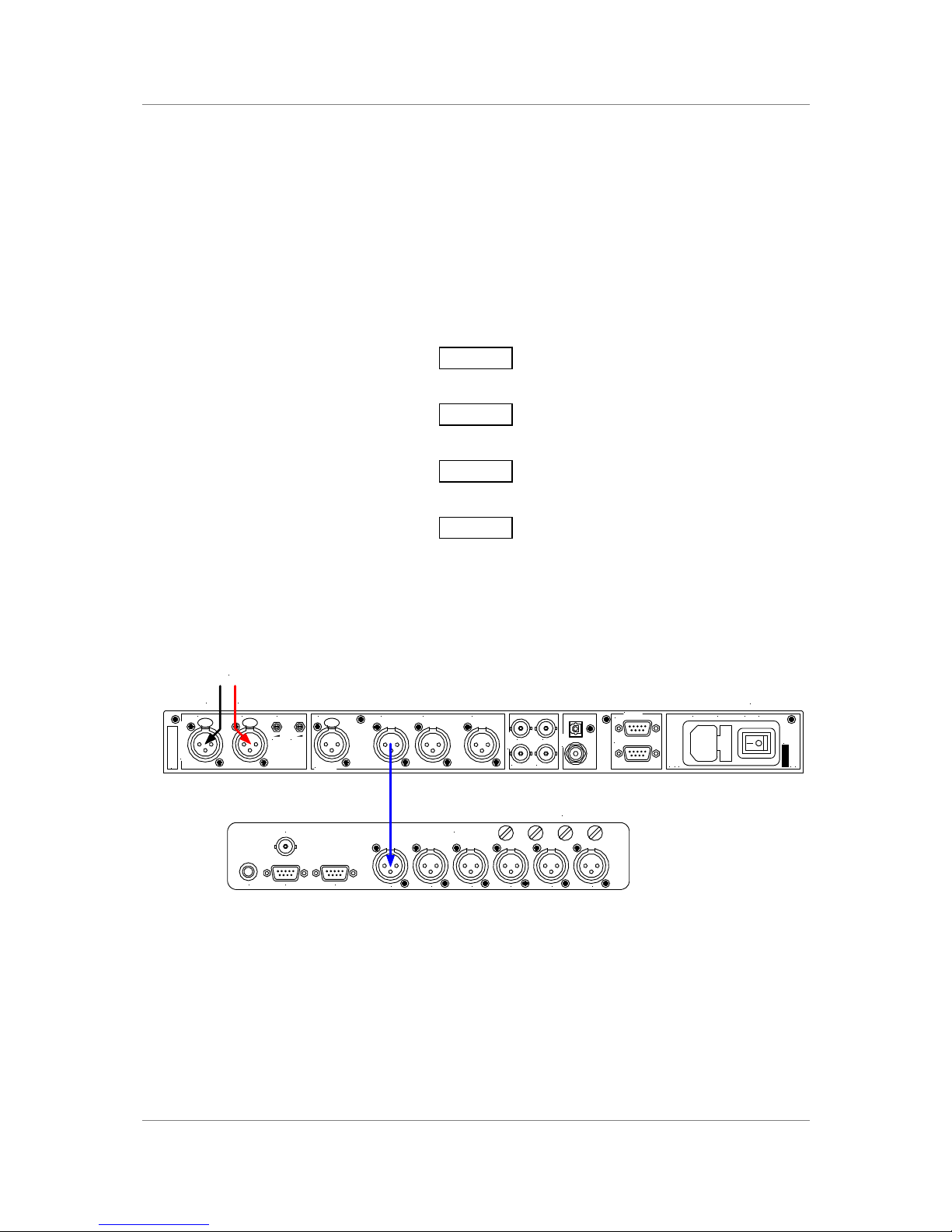
Figure 1 – Recording with a dCS 900 / 902
Set up like this, the dCS 900 / 902 will operate in Master mode, and the system it
is connected to will (have to) lock to it. You should have audio.
Use any output at 32 kS/s or 44.1 kS/s or 48 kS/s.
dCS 902 only: Use any output for double speed data at 88.2 kS/s or 96 kS/s.
Use (AES1 + AES2) for Dual AES at 88.2 kS/s or 96 kS/s
SPDIF
Reference In
AES/EBU
CH1(L)
Analogue Inputs
CH2(R)
CH1(L)
Sensitivity
CH2(R)
Output BOutput A
SDIF-2
CH1 CH2
CLK OutCLK In
Output C
Remote
See User Manual Before
Connecting To Supply
Serial No. On Underside.
Out
In
MAINS ON OFF
Before Removing Cover
Disconnect Mains
V 50/60Hz
FUSE (2AT)
PUSH PUSHPUSH
CH4CH3CH2CH1DIG3+4DIG1+2
INPUTS
RS-422ExtensionTimecode
Video
Sync In
L R
From analogue
source
dCS 900 / 902
Digital recorder
Page 9

dCS 900E / 902E User Manual Manual for Software Versions 1.3x to 1.5x
dCS Ltd 12th June 2000
Manual part no: DOC0029021E1 Page 9 Document No: OS-MA-D0002-902.1E1
Contact dCS on + 44 1799 531 999 email to: [email protected]
(inside the UK replace + 44 with 0) web site: www.dcsltd.co.uk
If you want to record less than 24 bit data, press the Word Length button
repeatedly until the required Word Length is displayed and press the Noise
Shaping button repeatedly until Auto is displayed.
Note that all the outputs are active simultaneously on the dCS 900 / 902. If the
mode the unit is in needs them to be different, they will be – otherwise they will
be the same, and may all be connected to external equipment simultaneously if
required.
Now you will need to familiarise yourself with how the front panel controls and
the menu system work.
do this: Read the short section on “The Software – The Menu” on page 18 so
you know how the buttons and menu work.
You may also find it convenient to refer to the Function Menu Guide while you
are getting to know the unit.
Page 10
dCS 900E / 902E User Manual Manual for Software Versions 1.3x to 1.5x
dCS Ltd 12th June 2000
Manual part no: DOC0029021E1 Page 10 Document No: OS-MA-D0002-902.1E1
Contact dCS on + 44 1799 531 999 email to: [email protected]
(inside the UK replace + 44 with 0) web site: www.dcsltd.co.uk
THE HARDWARE – CONTROLS AND CONNECTORS
Rear Panel
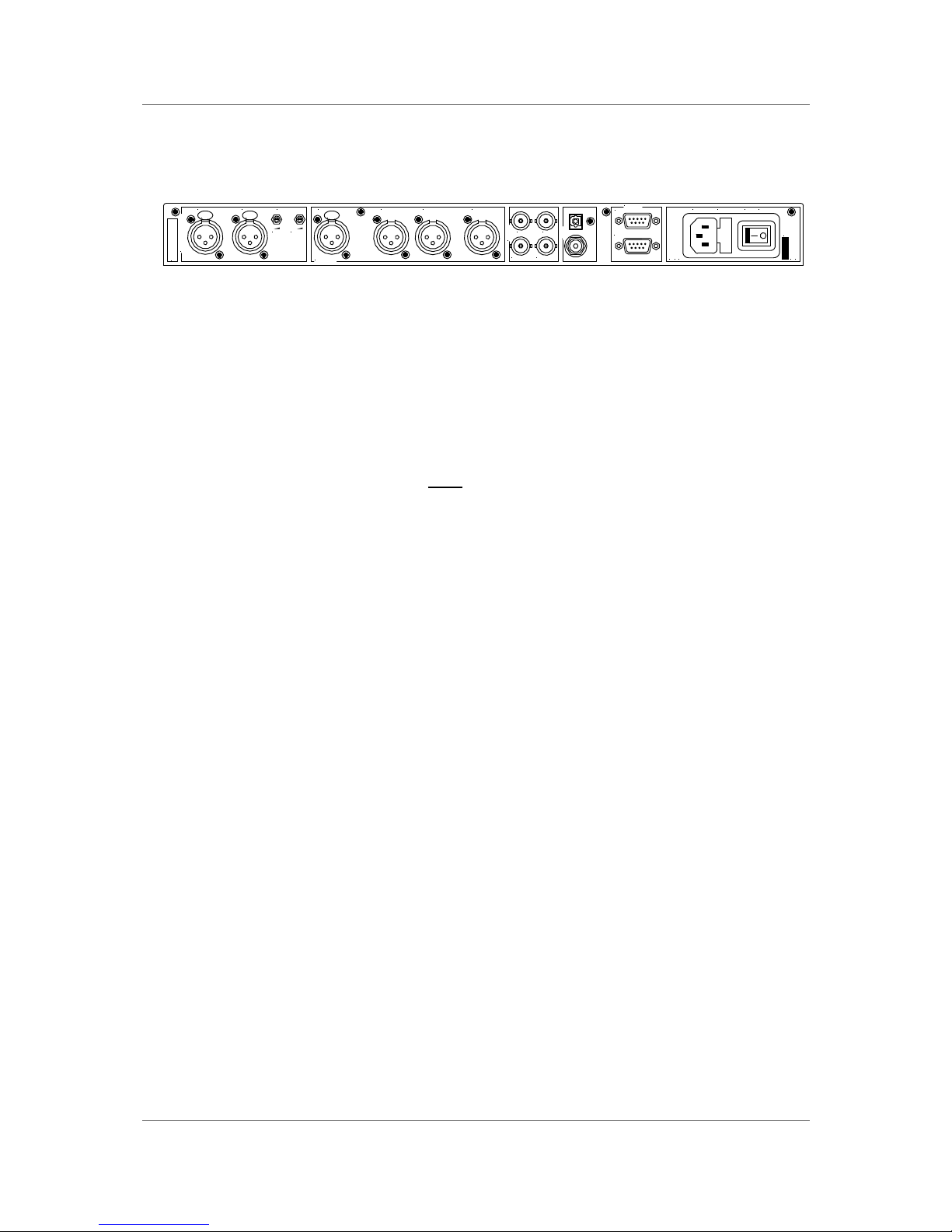
Figure 2 – Rear Panel
All input and output connectors are mounted on the rear panel. Individual
connectors are clearly identified by the panel legend. Viewed from the rear,
generally from left to right, the connectors are as follows:
Balanced Analogue Inputs 3 pin XLR female (2 off)
Input Level Adjustment (trimmers)
Two 20-turn potentiometers set the full scale input levels. These are factory
preset for full scale with input levels of +20dBu. If necessary, adjust with a
suitable trim tool or a small screwdriver. Turn clockwise for increased gain. Take
care to ensure the stereo inputs remain in balance. The trim range is ±6dB.
Reference In 3 pin XLR female
AES C (Reference) Digital Output 3 pin XLR male
Reference In is an AES/EBU reference input for synchronising the unit to a
Master Clock. AES C is a Reference loop through, directly coupled to it. A
terminating resistor may be turned on or off, using the menu, if several units are
to be daisy chained.
AES A & B Digital Outputs 3 pin XLR male (2 off)
Two AES/EBU outputs which may be used independently.
dCS 902 only: They may also be used as a Dual AES pair at 88.2 or 96kS/s.
SDIF-2 CH1, CH2 Data BNC (2 off)
These outputs are for SDIF-2 encoded PCM. They are both TTL level signals for
a 75 ohm line.
SDIF-2 Clk In BNC
SDIF-2 Clk Out BNC
This pair take in and give out Word Clock. Clock In is terminated and Clock
Out is regenerated internally, so these lines can be used for daisy chaining
many units together.
SPDIF Outputs RCA Phono & Toslink optical
The RCA Phono connector should be used with a 75 ohm line.
The Toslink connector should be used with a Toslink fibre-optic cable designed
for digital audio use. Pull out the plastic cover before use.
SPDIF
Reference In
AES/EBU
CH1(L)
Analogue Inputs
CH2(R)
CH1(L)
Sensitivity
CH2(R)
Output BOutput A
SDIF-2
CH1 CH2
CLK OutCLK In
Output C
Remote
See User Manual Before
Connecting To Supply
Serial No. On Underside.
Out
In
MAINS ON OFF
Before Removing Cover
Disconnect Mains
V 50/60Hz
FUSE (2AT)
PUSH PUSHPUSH
Page 11

dCS 900E / 902E User Manual Manual for Software Versions 1.3x to 1.5x
dCS Ltd 12th June 2000
Manual part no: DOC0029021E1 Page 11 Document No: OS-MA-D0002-902.1E1
Contact dCS on + 44 1799 531 999 email to: [email protected]
(inside the UK replace + 44 with 0) web site: www.dcsltd.co.uk
Remote In & Out 9 pin D type male (2 off)
If the Windows™ Remote software is in use, connecting Remote In to a com
port on a PC running the Remote Control program allows the unit to be
controlled by the PC. Remote Out may be connected to another suitably
equipped dCS unit, allowing several units to controlled by the same PC. In
addition, the unit may be software upgraded without removing the lid by
downloading new software via the Remote In port.
Connect up Remote ports using a 9-way screened cable, fitted with 9-way ‘D’type connectors at each end, wired pin 1 to pin 1, pin 2 to pin 2, etc. Suitable
cables are available from dCS.
Mains Supply 3 pin IEC (CEE22)
Switched, fused and filtered IEC mains connector.
Additional Information
As well as connectors, the rear panel displays the following information about
the unit, near the mains supply connector:
Mains Voltage The actual voltage setting supplied.
Manufacturers Name and Country of origin (dCS Ltd, UK)
The underside of the unit will have a label on that contains a number such as
900 1A2 3B4 5C6 7D8 12345. This is the serial number, but it also contains
vital configuration information. We will need this number (all of it) to give you
support over the phone, or to ship you software updates.
Digital Data Formats
The unit provides five digital data i/o formats,
AES/EBU (often referred to as AES3)
Dual AES (part of the AES3 spec)
SDIF-2
SPDIF (electrical)
SPDIF (optical)
For all formats, the incoming Channel Status and User messages are handled
according to a priority system – they are either passed through, where this is
sensible, or generated and inserted by the unit.
The enhanced AES/EBU interface is fully implemented. Each channel has its
own parity and data validity bit, as well as User and Channel Status messages.
Cyclic Redundancy Counts (CRC's) are generated from the Channel Status
message. The Dual AES interface allows a 96 or 88.2 kS/s 24 bit signal to be
coded as two standard 48 or 44.1 kS/s 24 bit AES data streams, recorded as
four channels on a recorder with standard capacity, replayed and decoded back
into a single data stream / channel pair.
SDIF-2 message bits are internally set to zero, with the exception of the block
code, which is implemented.
The SPDIF interface has no CRC’s – as per definition. The data structure for
electrical and optical interfaces is identical.
Page 12
dCS 900E / 902E User Manual Manual for Software Versions 1.3x to 1.5x
dCS Ltd 12th June 2000
Manual part no: DOC0029021E1 Page 12 Document No: OS-MA-D0002-902.1E1
Contact dCS on + 44 1799 531 999 email to: [email protected]
(inside the UK replace + 44 with 0) web site: www.dcsltd.co.uk
Front Panel
A to D Converter
dCS 902
Data Conversion Systems
2
4
9
dCSdCS
BIT
kHz
Sample
Rate
Multiplier Mute
Word
Length
Noise
Shaping
Overload
Level
Overload Master Slave
Output
Format
MENU
Step Set
kS/s
Sample Rate
6
A to D Converter
dCS 900
Data Conversion Systems
2
4
dCSdCS
BIT
Sample
Rate
Mute
Word
Length
Noise
Shaping
Overload
Level
Overload Master Slave
MENU
Step Set
kS/s
Sample Rate
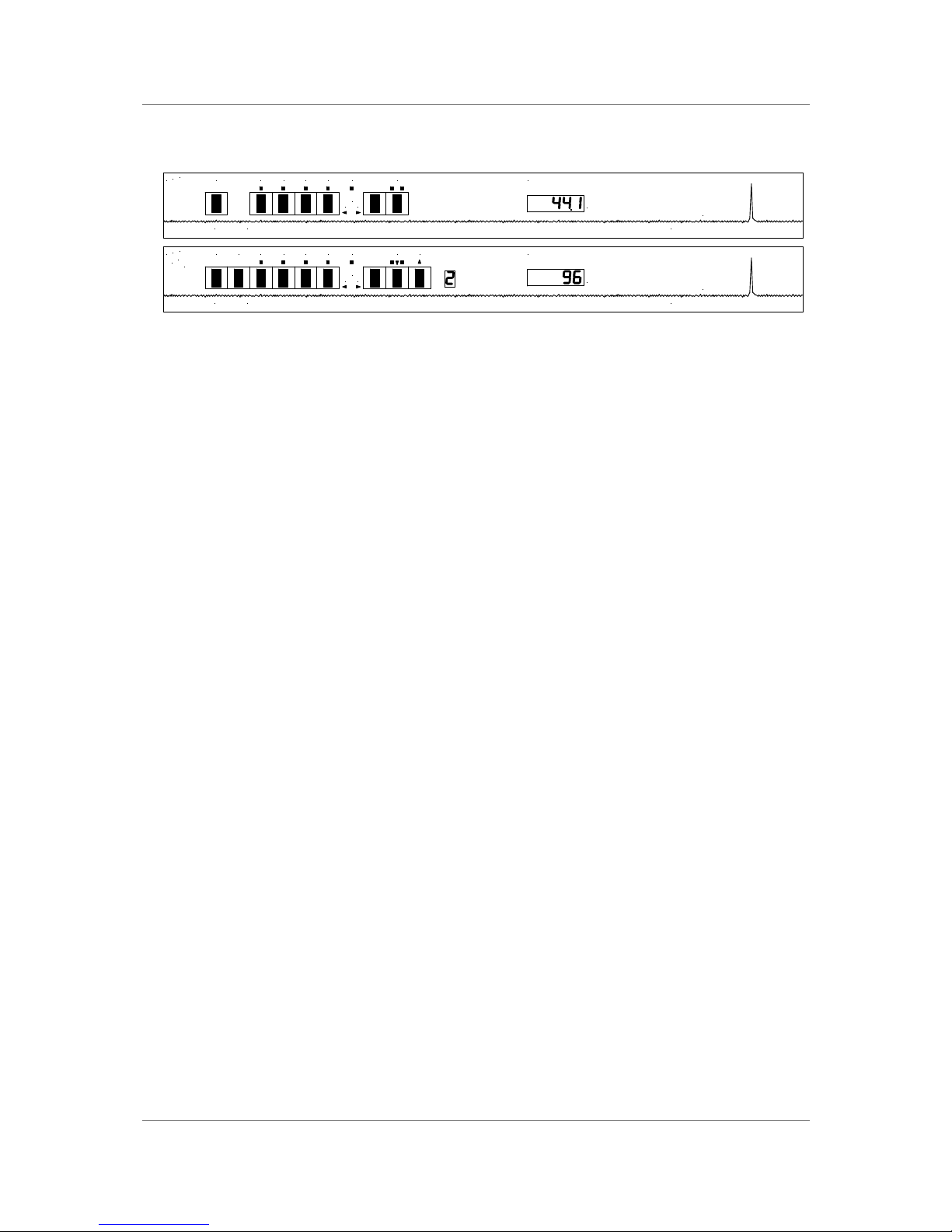
Figure 3 – Front Panel
The dCS 900 / 902 uses a combination of front panel buttons for frequently
changed functions and a step through menu for features you might set and
forget.
Sample Rate -
Multiplier -
Press the Sample Rate button repeatedly to cycle through the sample rates.
dCS 900:
48 ... 44.1 ... 32 ... 48 ... etc.
dCS 902:
96 ... 88.2 ... 48 ... 44.1 ... 32 ... 96 ... etc.
The dCS 902 also features a Multiplier button which allows you to step through
more quickly. Press the Multiplier button repeatedly to cycle through in one of
the following sequences, depending on the starting sample rate:
48 ... 96 ... 32 ... 48 ... 96 ... etc.
44.1 ... 88.2 ... 44.1 ... 88.2 ... etc.
To change sample rates quickly, use the two buttons together. For example, to
change from 88.2 kS/s to 96 kS/s press Sample Rate once then Multiplier
once. Do not press the buttons too fast as a delay is built in to the software. The
sample rate selected is shown on the LED display in the centre of the panel.
Mute -
This button forces a mute, in addition to the automatic ones. The digital outputs
are automatically muted at power up and when the sample rate is changed or
the unit is locking to a reference source. A forced mute is indicated by the mute
LED (above the mute switch) lighting up. In normal use, pressing the Mute
button mutes the digital outputs and lights the mute LED. Pressing the Mute
button again unmutes the ADC, as long as no automatic mute is being applied.
Page 13
dCS 900E / 902E User Manual Manual for Software Versions 1.3x to 1.5x
dCS Ltd 12th June 2000
Manual part no: DOC0029021E1 Page 13 Document No: OS-MA-D0002-902.1E1
Contact dCS on + 44 1799 531 999 email to: [email protected]
(inside the UK replace + 44 with 0) web site: www.dcsltd.co.uk
Word Length -
Noise Shaping -
The AES/EBU format accommodates data up to 24 bits. If a shorter word is
needed and the extra bits are just ignored, the result is typical “digital” sound
due to the abrupt chopping off of the low level signal information.
To avoid this, the dCS 900 / 902 allows proper truncation of the data and uses
Noise Shaping to maintain low level performance. See the section on “Word
Length Reduction” on page 50 for some background on this. If you do use
Word Length truncation, make sure that Noise Shaping is not set to OFF
without realising it.
Pressing the Word Length button repeatedly cycles the word length through the
sequence:
24, 23, 22, 21, 20, 19, 18, 17, 16, 24, etc.
The Word Length is briefly shown on the main display, and if a setting other than
the maximum is set, the word length LED (above the button) lights.
Noise Shaping is a technique which improves the noise performance of the ADC
in the audio band by moving the quantisation noise energy (introduced by
reducing the word length) from the middle of the band, where the ear is most
sensitive, to the top end or ultrasonic region, where the ear is less sensitive or
insensitive. See the section “Word Length Reduction” on page 50 for more
background.
Pressing the Noise Shaping button repeatedly cycles the unit through 5 noise
Shaping characteristics. The characteristic is shown briefly on the main display.
Auto Unit sets noise shaping automatically, depending
on word length:
24 bits – no noise shaping
20 to 23 bits – 1st order noise shaping
16 to 19 bits – 3rd order noise shaping
Off No noise shaping
1st 1st order noise shaping
3rd 3rd order noise shaping
9th 9th order noise shaping
The noise shaping LED (above the button) lights when the setting is other
than Auto.
Overload Level Menu Step
The Overload Level button is dual function – on its own (blue type on the front
panel) it sets the level at which overloads are detected by the unit. With the
other menu buttons (white type on the front panel) it is the menu Step button.
Overload detection is normally set to full scale. The detection level may be
reduced in 0.1dB steps down to -3dB0 by pressing the Overload Level button
repeatedly or holding it down. The set level is shown on the display for a few
seconds. The overload level LED (above the button) lights when the setting is
other than full scale (0.0dB0).
For Menu operation as the Step button, see the section “The Software – The
Menu” on page 18.
Page 14
dCS 900E / 902E User Manual Manual for Software Versions 1.3x to 1.5x
dCS Ltd 12th June 2000
Manual part no: DOC0029021E1 Page 14 Document No: OS-MA-D0002-902.1E1
Contact dCS on + 44 1799 531 999 email to: [email protected]
(inside the UK replace + 44 with 0) web site: www.dcsltd.co.uk
Overload Indicator (Overload LED)
This overload LED lights for a few seconds when the set overload level is
exceeded by a signal peak. The detection circuitry monitors both input and
digital filtering circuitry for overload conditions. The analogue input sensitivity
trims mounted on the rear panel should be set so that the overload indicator
does not light on signal peaks.
The overload indication given by the dCS 900 / 902 is comprehensive. The
detection circuitry monitoring the digital filter does not simply check the final
output word but all the data from which the output word is formed. If any of these
overload (this may not be apparent from the output data), an overload is flagged.
The filter itself has sufficient numerical accuracy that if the input data is not
overloaded, the filter computations cannot generate an overload - only a raw
data overload can cause an error. The overload indication is thus much more
accurate than any external meter based indication - for this reason it is stored in
the AES/EBU validity bit for later reference.
Menu Set -
The Set button is used with the other menu buttons (white type on the front
panel). See the section “The Software – The Menu” on page 18.
Master/Slave Menu Down
The Master/Slave button is dual function – on its own (blue type on the front
panel) it sets the clocking mode (master or slave). With the other menu buttons
(white type on the front panel) it is the menu Down button.
In Master mode, the calibrated voltage controlled crystal oscillators (VCXOs)
inside the unit generate an accurate sample rate. The LED labelled Master will
be lit to indicate this. If a Master Clock is available, this may be connected to the
Reference In connector (for AES/EBU reference) or the Clk In connector (for
SDIF-2 Word Clock). To slave the unit to the Master Clock, press the
Master/Slave button. The unit will attempt to lock to the Reference - this will
take a few seconds. If lock is achieved, the Slave LED will light up brightly and
the Master LED will turn off. To return to Master mode, press the Master/Slave
button again.
If both AES Reference and Word Clock are connected, pressing the
Master/Slave button cycles through the sequence:
Master ... AES Reference ... Word Clock ... Master ... etc.
If the active reference source is lost, the unit will select the next option in the
sequence.
If the Auto-Slave option (see page 21) is turned On the unit will automatically
slave when a suitable reference is connected. If both AES Reference and Word
Clock are connected, AES Reference takes priority. Word Clock may be
selected by pressing the Master/Slave button – it moves down the priority list.
Page 15
dCS 900E / 902E User Manual Manual for Software Versions 1.3x to 1.5x
dCS Ltd 12th June 2000
Manual part no: DOC0029021E1 Page 15 Document No: OS-MA-D0002-902.1E1
Contact dCS on + 44 1799 531 999 email to: [email protected]
(inside the UK replace + 44 with 0) web site: www.dcsltd.co.uk
dCS 902 only: Once slaved, the unit can internally multiply the reference input
sample rate by 2, if required, by pressing the Multiplier button. The Master
Clock must be set to a suitable sample rate:
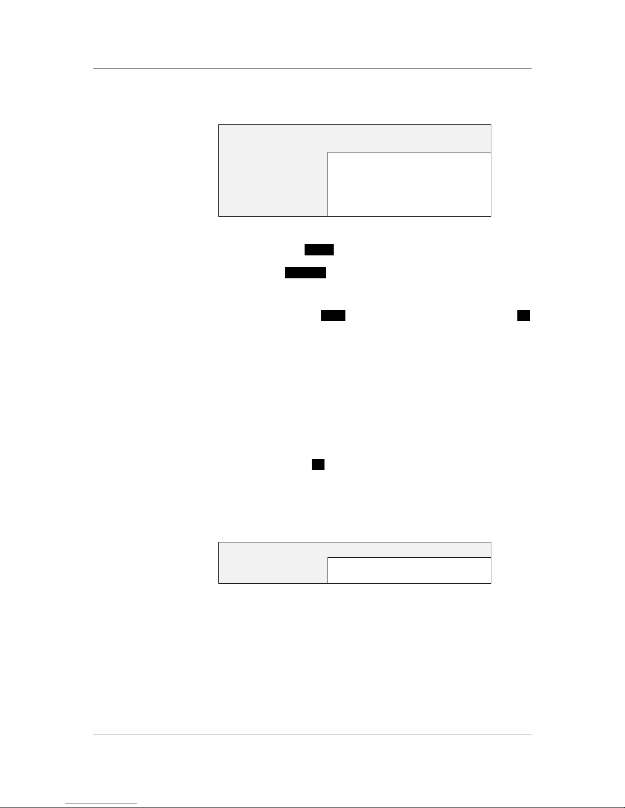
Master Clock Sample
Rate (kS/s)
dCS 902 Sample Rate (kS/s)
32 32
44.1 44.1 or 88.2
48 48 or 96
88.2 88.2
96 96
Table 1 - Reference Clock and Sample Rates
For Menu operation as the Down button, see the section” on page 18.
Output Format Menu Up
dCS 902 only: The Output Format button is dual function – on its own (blue type
on the front panel) it sets the output format to Single AES (1) or Dual AES (2).
With the other menu buttons (white type on the front panel) it is the menu Up
button.
Pressing the Output Format button repeatedly causes the output format to
cycle through the allowed options from the sequence:
Single AES ... Dual AES ... Single AES ... etc.
For sample rates of 48kS/s or less, Single AES is the only option.
IMPORTANT! If the Output Format is set to 2 (Dual AES), do not use the SPDIF or
SDIF-2 outputs.
For Menu operation as the Up button, see the section “The Software – The
Menu” on page 18.
Mode Display -
dCS 902 only: The single digit LED mode display to the right of the Output
Format button shows the output format:
Display
Output Format
1 Single AES
2 Dual AES
Table 2 - Output Data format indication, higher sample rates
When the Output Format is selected, the main display briefly shows the format
code:
A1 for Single AES, Standard speed encoding
b1 for Single AES, Double speed encoding
b2 for Dual AES, Standard speed encoding
In Single AES mode, the same data stream is available on both AES outputs.
In Dual AES mode, the data stream is available on AES A & AES B outputs.
Page 16

dCS 900E / 902E User Manual Manual for Software Versions 1.3x to 1.5x
dCS Ltd 12th June 2000
Manual part no: DOC0029021E1 Page 16 Document No: OS-MA-D0002-902.1E1
Contact dCS on + 44 1799 531 999 email to: [email protected]
(inside the UK replace + 44 with 0) web site: www.dcsltd.co.uk
dCS equipment encodes messaging into the various data streams to enable
receiving equipment to tell what is going on, and to decide which wire is which,
in the unlikely event of user wiring errors. Not all equipment from other
manufacturers does this, so:
IMPORTANT! Take care when connecting Dual AES as it is easy to connect the wires in the
wrong order. If this is not detected, the Left and Right channels will be
swapped on the recording. Numbering each connector is a sensible
precaution.
Sample Rate Display -
The main LED display generally shows the sample rate, in kS/s. When other
parameters are set, it briefly shows the new setting (Word Length, Noise
Shaping, etc) then reverts to its normal display. In the case of an error condition,
it will display an error message.
If the unit is being slaved, the display also indicates which input connector it is
slaved to.
xxx The sample rate, in kS/s (32, 44.1, 48, 88.2 or 96).
b xxx Slaved to Clk In.
r xxx Slaved to AES Reference in.
d xxx Temporary display during locking – the unit has
detected the base reference sample rate and is
attempting to lock to it.
. xxx Temporary display during locking – the unit is lining
up Clk Out to Clk in.
Important error messages are given below – a full list is given in the section
Error Codes and Messages on page 58.
BadFs The clock source is not in pull-in range, or is poorly
formatted. The unit cannot lock to it.
Err.xy An error has been detected. Please refer to
“Internal Device Error Codes” on page 58 for
more specific details on error codes.
Hot The unit is overheating, probably due to inadequate
ventilation. Please check positioning and cooling.
Ouch The “Hot” warning has been ignored and the unit is
getting so hot damage may follow.
(blank) If the display is completely blank for any significant
period, try switching off for 10 seconds then
switching on again. If this does not solve the
problem, contact your distributor or dCS.
The display is also used for Menu options.
Page 17

dCS 900E / 902E User Manual Manual for Software Versions 1.3x to 1.5x
dCS Ltd 12th June 2000
Manual part no: DOC0029021E1 Page 17 Document No: OS-MA-D0002-902.1E1
Contact dCS on + 44 1799 531 999 email to: [email protected]
(inside the UK replace + 44 with 0) web site: www.dcsltd.co.uk
Page 18
dCS 900E / 902E User Manual Manual for Software Versions 1.3x to 1.5x
dCS Ltd 12th June 2000
Manual part no: DOC0029021E1 Page 18 Document No: OS-MA-D0002-902.1E1
Contact dCS on + 44 1799 531 999 email to: [email protected]
(inside the UK replace + 44 with 0) web site: www.dcsltd.co.uk
THE SOFTWARE – THE MENU
Overview
The dCS 900 / 902 has many other functions that either need to be accessed only
occasionally, or are informative in nature. These functions can be accessed
either by the Remote software, running on a PC and connected to the unit by an
RS-232 link - or (in most cases) by the Menu. If a function is set by the menu or
the Remote, the unit remembers it, and it will be set this way for ever (or until
you set it to something different). You can customise your unit in this way.
Information only items are displayed for a time, then the display reverts to
normal.
Menu buttons are indicated by white text on the front panel. There are for:
Step otherwise Overload Level
Set
Down otherwise Master/Slave
Up otherwise Output Format (dCS 902 only)
Entering the Menu -
The Menu is entered by holding down the Step button and then pressing the Set
button once. The display will show:
Func
You are now in the menu, and the menu buttons now have their alternate
meanings.
Moving through the Menu -
Press the Step button again to step through the Menu items listed below. When
you reach the required item, press the Set button to change its setting. This
either toggles the previous state, or causes an information function to read out,
or enters a lower level (as in the Tone generator, for example). If you have
entered a lower level, pressing Step steps through its options. When you reach
the one you want, press Set and then use the Up or Down buttons to increase
or decrease a value (such as Level or Frequency on the Tone generator).
If no changes are made in 4 seconds, the unit exits the Menu. When one item
has been set, press the Step button again if you wish to continue cycling
through the Menu.
There is a knack in doing this easily – once it has been gained, it becomes very
easy to use the functions it accesses.
Page 19
dCS 900E / 902E User Manual Manual for Software Versions 1.3x to 1.5x
dCS Ltd 12th June 2000
Manual part no: DOC0029021E1 Page 19 Document No: OS-MA-D0002-902.1E1
Contact dCS on + 44 1799 531 999 email to: [email protected]
(inside the UK replace + 44 with 0) web site: www.dcsltd.co.uk
The Menu Sequence
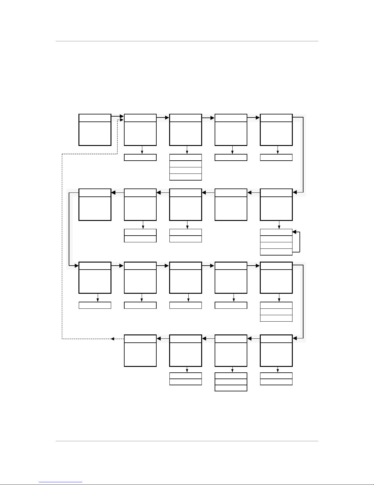
To access the Function Menu, hold down the
Menu Step
button and press the
Menu Set
button.
To step through the Menu items, press the
Menu Step
button repeatedly.
To select an item or one of its options, press the
Menu Set
button.
dCS 900E
: Use
Master/Slave
button to alter
RS232
address.
dCS 902E
: Use
Menu Up
&
Menu Down
buttons to alter
RS232
address, Tone
Level
and Tone
Frequency.
To exit the Function Menu, either select the
End
item or wait five seconds.
Func Issue Filt DSD DSD 4
Opens the
Function Menu
Displays the
fitted software
issue number
Selects an
alternative
filter
DSD mode is
available on the
dCS 904
only
DSD mode is
available on the
dCS 904
only
1.5x Filt 1 Off Off
Filt 2
…
Filt n
Phone Heat 7 - Seg Test Tone
Displays
dCS'
telephone
number
Displays the
internal
temperature
Disables the 7-
segment display
when idle.
Runs a display
self test routine
Turns on and
sets (
dCS 902E
only) a test tone
Fahrenheit On Level (dB)
Celsius Off Freq (kHz)
On / Off
Up
Part S - No RS232 BNC O Ref In
Displays the
control PCB
part number
Displays the
control PCB
serial number
Displays and
sets the unit's
RS232 address
This feature is
available on the
dCS 904
only
Sets the mode
of the AES Ref
I/O connectors
dCS002540? 0002-540-?-? 0 ... 99 SDIF Loop
Loop.t
Int
End Loc Offst A - SL
Exits the
Function Menu
Locks out the
front panel
controls
dCS 902E
only:
Trims the
mastermode
sample rate
Automatically
slaves when ref
input available
Off +9.9 ppm Off
v1.5x software
On 0 ppm On
-9.9 ppm
Figure 4 – Menu Sequence
Page 20

dCS 900E / 902E User Manual Manual for Software Versions 1.3x to 1.5x
dCS Ltd 12th June 2000
Manual part no: DOC0029021E1 Page 20 Document No: OS-MA-D0002-902.1E1
Contact dCS on + 44 1799 531 999 email to: [email protected]
(inside the UK replace + 44 with 0) web site: www.dcsltd.co.uk
Menu Items
Issue -
Displays the software issue- when Set is pressed.
Filt -
Selects one of several anti-alias filter- responses. The filters should be
evaluated by ear. Filt1 gives the sharpest cut off, just below half the sampling
frequency. This is the normal setting. Filt2, Filt3, Filt4 give progressively more
relaxed responses, degrading the alias performance but sharpening the impulse
response. This affects the stereo or multi-channel image. Different filters may
be appropriate for different material.
DSD -
DSD 4 -
DSD and DSD 4 modes are only available on the dCS 904. In the dCS 900 & 902,
they are permanently set to Off.
Tone -
This accesses a sinewave test generator. On the dCS 900, the tone is fixed at
1kHz and -18dB0. Press Set to toggle it On and Off.
On the dCS 902, the tone level and frequency can be adjusted. Pressing Set
enters a submenu, which accesses the following functions:
Level The tone level, from –120dB0 to 0dB0. It can be
changed in 0.1dB steps using the Up and Down
buttons.
Freq The tone frequency, from 0.001kHz (1Hz) to just
under half the sample rate. It can be changed
using the Up and Down buttons. The step size is
1Hz for tones up to 100Hz, 10Hz up to 1kHz and
100Hz above 1kHz.
On/Off Toggles whether the generator is on or off.
Up Allows the menu to be re-entered to set other
functions. Alternatively, if left, the menu will just
time out keeping the last settings.
At power up, the tone generator is set to –18dB0, 1kHz and turned Off.
Test -
Runs a display self test routine. When successfully completed, the unit displays
Pass and returns to normal operation. Otherwise an error message Err.xy is
displayed – please refer to “Error Codes and Messages” on page 58 for more
specific information.
7-Seg -
Disables the 7 segment LED display. When set to Off, the display turns off 4
seconds after the last button press. A dot in the lower right hand corner of the
display remains lit to indicate that the display has been deliberately blanked.
The display springs back into life (temporarily) if the menu is used subsequently.
Error or warning messages are displayed regardless of this setting.
Page 21

dCS 900E / 902E User Manual Manual for Software Versions 1.3x to 1.5x
dCS Ltd 12th June 2000
Manual part no: DOC0029021E1 Page 21 Document No: OS-MA-D0002-902.1E1
Contact dCS on + 44 1799 531 999 email to: [email protected]
(inside the UK replace + 44 with 0) web site: www.dcsltd.co.uk
Heat -
Displays the internal temperature of the unit. Press Set to toggle between
Fahrenheit and Celsius.
Phone -
dCS telephone number scrolls across the display
Part -
The control board part number (version) scrolls along the display.
S-No -
The control board serial number scrolls along the display. You will need to tell us
this number if you call us for help.
RS232 -
Displays - and allows access to – the unit’s RS-232 identity code (an address
between 0 and 99). This is used by the remote control software, to send specific
messages to specific units. Use Up and Down to change this address if you are
operating several units in a multichannel set up. On dCS 900, press (or hold
down) the Master/Slave button to change this setting.
IMPORTANT! Each unit in a daisy chain MUST be set to a different RS-232 address.
BNC O -
This feature is available on the dCS 904 only. In the dCS 900 & 902, it is
permanently set to SDIF.
Ref In -
Sets the mode of the AES Reference In / AES C Out connectors. The options
are:
Loop Loops the Reference In through to the AES C
output, with no termination resistor (termination is
then about 1kohm, so several units can be daisy
chained).
Loop.t As above, but terminates the input. Use at the end
of a daisy chain.
Int The output (and input in parallel – beware!) is
internally driven, with the same signal as AES 1.
A-SL -
Turns Auto-slaving On or Off. When set to On, connecting an AES/EBU
reference or a word clock in causes the unit to slave and lights the Slave LED.
If both are present, the unit picks the highest priority one (AES/EBU) unless the
Master/Slave button is used to move down the priority list. When set to Off, the
unit does not react when a reference is connected.
IMPORTANT! Ensure the Ref In menu item is set to Loop or Loop.t before connecting an
AES Reference.
Page 22

dCS 900E / 902E User Manual Manual for Software Versions 1.3x to 1.5x
dCS Ltd 12th June 2000
Manual part no: DOC0029021E1 Page 22 Document No: OS-MA-D0002-902.1E1
Contact dCS on + 44 1799 531 999 email to: [email protected]
(inside the UK replace + 44 with 0) web site: www.dcsltd.co.uk
Offst -
dCS 902 only: Trims the appropriate VCXO frequency- in master mode, by up to
±9.9ppm in 0.1ppm steps. Use the Up and Down buttons to change this setting,
hold a button down to accelerate the change. The trim is remembered.
Loc -
Panel Lock-, normally Off. Set to On to prevent unauthorised changes using
buttons. The menu has to be accessed in the usual way to turn the lock off
again.
End -
Exits the menu.
Page 23

dCS 900E / 902E User Manual Manual for Software Versions 1.3x to 1.5x
dCS Ltd 12th June 2000
Manual part no: DOC0029021E1 Page 23 Document No: OS-MA-D0002-902.1E1
Contact dCS on + 44 1799 531 999 email to: [email protected]
(inside the UK replace + 44 with 0) web site: www.dcsltd.co.uk
Page 24
dCS 900E / 902E User Manual Manual for Software Versions 1.3x to 1.5x
dCS Ltd 12th June 2000
Manual part no: DOC0029021E1 Page 24 Document No: OS-MA-D0002-902.1E1
Contact dCS on + 44 1799 531 999 email to: [email protected]
(inside the UK replace + 44 with 0) web site: www.dcsltd.co.uk
TYPICAL APPLICATIONS
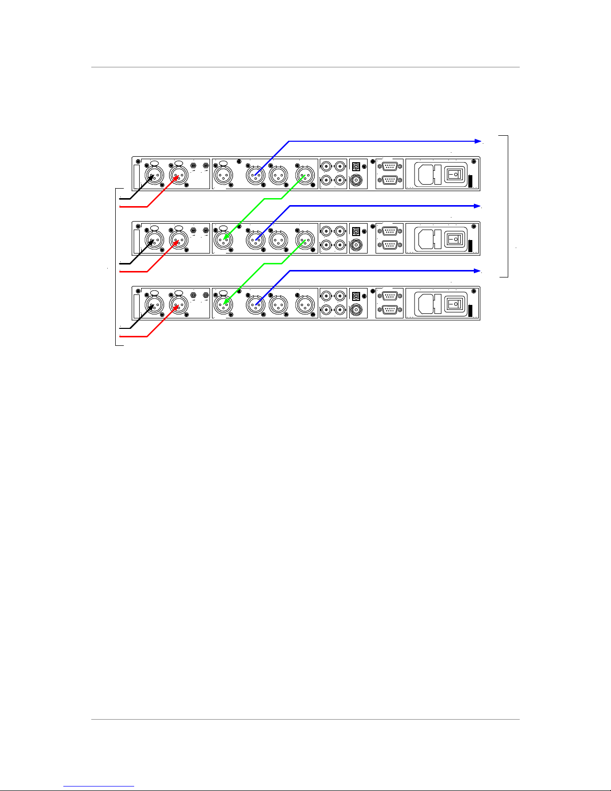
Six Channel Set Up Sync’ed to AES Reference
Figure 5 – Six Channel Set Up Sync’ed to AES Reference
do this: For the top ADC, set to the sample rate you wish to record, set Ref In to
Int (Internal sync) and select a filter.
do this: For the middle ADC, set Ref In to Loop, turn A-SL (Autoslave) On and
select a filter.
do this: For the bottom ADC, set Ref In to Loop.t, turn A-SL On and select a filter.
do this: For all ADC’s, if you are recording less than 24 bit words, set Word
Length as required and set Noise Shaping to Auto.
The units self align quite accurately (see the section “Sample Alignment” on
page 32 onwards).
This arrangement will work with one, two or more ADC’s (the top one must be
set to Int).
You can record from the SDIF-2 output or one of the SPDIF outputs if
preferred.
SPDIF
Reference In
AES/EBU
CH1(L)
Analogue Inputs
CH2(R)
CH1(L)
Sensitivity
CH2(R)
Output BOutput A
SDIF-2
CH1 CH2
CLK OutCLK In
Output C
Remote
See User Manual Before
Connecting To Supply
Serial No. On Underside.
Out
In
MAINS ON OFF
Before Removing Cover
Disconnect Mains
V 50/60Hz
FUSE (2AT)
PUSH PUSHPUSH
CH1
From analogue sources
dCS 900 / 902
CH2
SPDIF
Reference In
AES/EBU
CH1(L)
Analogue Inputs
CH2(R)
CH1(L)
Sensitivity
CH2(R)
Output BOutput A
SDIF-2
CH1 CH2
CLK OutCLK In
Output C
Remote
See User Manual Before
Connecting To Supply
Serial No. On Underside.
Out
In
MAINS ON OFF
Before Removing Cover
Disconnect Mains
V 50/60Hz
FUSE (2AT)
PUSH PUSHPUSH
CH3
dCS 900 / 902
CH4
SPDIF
Reference In
AES/EBU
CH1(L)
Analogue Inputs
CH2(R)
CH1(L)
Sensitivity
CH2(R)
Output BOutput A
SDIF-2
CH1 CH2
CLK OutCLK In
Output C
Remote
See User Manual Before
Connecting To Supply
Serial No. On Underside.
Out
In
MAINS ON OFF
Before Removing Cover
Disconnect Mains
V 50/60Hz
FUSE (2AT)
PUSH PUSHPUSH
CH5
dCS 900 / 902
CH6
CH1 & 2
CH3 & 4
CH5 & 6
To digital recorder
Page 25
dCS 900E / 902E User Manual Manual for Software Versions 1.3x to 1.5x
dCS Ltd 12th June 2000
Manual part no: DOC0029021E1 Page 25 Document No: OS-MA-D0002-902.1E1
Contact dCS on + 44 1799 531 999 email to: [email protected]
(inside the UK replace + 44 with 0) web site: www.dcsltd.co.uk
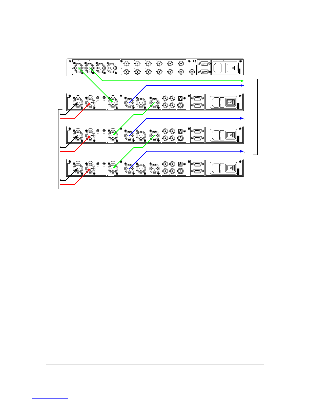
Six Channel Set Up Sync’ed to Master Clock (AES)
Figure 6 – Six Channel Set Up Sync’ed to Master Clock (AES)
do this: Set the dCS 992 Master Clock to the sample rate you wish to record at
and set the recorder to slave to it.
do this: For all 3 ADC’s, set A-SL (Autoslave) to On and select a filter. If you are
recording less than 24 bit words, set Word Length as required and set
Noise Shaping to Auto.
do this: For the ADC’s processing CH1 – 4, set Ref In to Loop. For the bottom
ADC, set Ref In to Loop.t.
The Master Clock helps reduce jitter. The units self align quite accurately (see
section “Sample Alignment” on page 32 onwards). This arrangement will work
with one, two or more ADC’s.
You can record from the SDIF-2 output or one of the SPDIF outputs if
preferred.
SPDIF
Reference In
AES/EBU
CH1(L)
Analogue Inputs
CH2(R)
CH1(L)
Sensitivity
CH2(R)
Output BOutput A
SDIF-2
CH1 CH2
CLK OutCLK In
Output C
Remote
See User Manual Before
Connecting To Supply
Serial No. On Underside.
Out
In
MAINS ON OFF
Before Removing Cover
Disconnect Mains
V 50/60Hz
FUSE (2AT)
PUSH PUSHPUSH
CH1
From analogue sources
dCS 900 / 902
CH2
AES 1 AES 2 AES 3 AES 4
AES/EBU Outputs
Wordclock Outputs
1 2 3 4 5 6
7 8 9 10 11 12
External
Sync
Remote
In
Loop
Out
Mains Fuse (2AT)
On Off
V 50-60Hz
Disconnect mains
before removing cover
dCS 992
SPDIF
Reference In
AES/EBU
CH1(L)
Analogue Inputs
CH2(R)
CH1(L)
Sensitivity
CH2(R)
Output BOutput A
SDIF-2
CH1 CH2
CLK OutCLK In
Output C
Remote
See User Manual Before
Connecting To Supply
Serial No. On Underside.
Out
In
MAINS ON OFF
Before Removing Cover
Disconnect Mains
V 50/60Hz
FUSE (2AT)
PUSH PUSHPUSH
CH3
dCS 900 / 902
CH4
SPDIF
Reference In
AES/EBU
CH1(L)
Analogue Inputs
CH2(R)
CH1(L)
Sensitivity
CH2(R)
Output BOutput A
SDIF-2
CH1 CH2
CLK OutCLK In
Output C
Remote
See User Manual Before
Connecting To Supply
Serial No. On Underside.
Out
In
MAINS ON OFF
Before Removing Cover
Disconnect Mains
V 50/60Hz
FUSE (2AT)
PUSH PUSHPUSH
CH5
dCS 900 / 902
CH6
CH1 & 2
CH3 & 4
CH5 & 6
Clock
To digital recorder
Page 26
dCS 900E / 902E User Manual Manual for Software Versions 1.3x to 1.5x
dCS Ltd 12th June 2000
Manual part no: DOC0029021E1 Page 26 Document No: OS-MA-D0002-902.1E1
Contact dCS on + 44 1799 531 999 email to: [email protected]
(inside the UK replace + 44 with 0) web site: www.dcsltd.co.uk
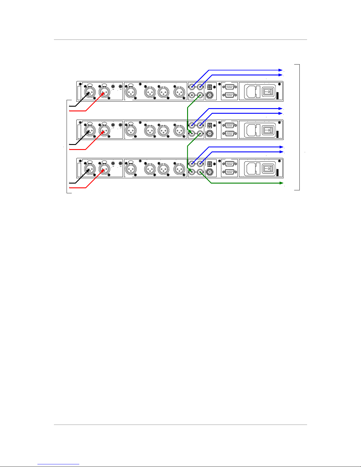
Six Channel Set Up Sync’ed to Word Clock
Figure 7 – Six Channel Set Up Sync’ed to Word Clock
do this: For the top ADC, set to the sample rate you wish to record, set Ref In to
Int (Internal sync) and select a filter.
do this: For the other ADC’s, turn A-SL (Autoslave) On and select a filter.
do this: If you are recording less than 24 bit words, set Word Length as required
and set Noise Shaping to Auto on all ADC’s.
The data streams will be synchronous.
This arrangement will work with one, two or more ADC’s (the top one must be
set to Int).
You can record from the AES outputs or one of the SPDIF outputs if preferred.
SPDIF
Reference In
AES/EBU
CH1(L)
Analogue Inputs
CH2(R)
CH1(L)
Sensitivity
CH2(R)
Output BOutput A
SDIF-2
CH1 CH2
CLK OutCLK In
Output C
Remote
See User Manual Before
Connecting To Supply
Serial No. On Underside.
Out
In
MAINS ON OFF
Before Removing Cover
Disconnect Mains
V 50/60Hz
FUSE (2AT)
PUSH PUSHPUSH
CH1
From analogue sources
dCS 900 / 902
CH2
SPDIF
Reference In
AES/EBU
CH1(L)
Analogue Inputs
CH2(R)
CH1(L)
Sensitivity
CH2(R)
Output BOutput A
SDIF-2
CH1 CH2
CLK OutCLK In
Output C
Remote
See User Manual Before
Connecting To Supply
Serial No. On Underside.
Out
In
MAINS ON OFF
Before Removing Cover
Disconnect Mains
V 50/60Hz
FUSE (2AT)
PUSH PUSHPUSH
CH3
dCS 900 / 902
CH4
SPDIF
Reference In
AES/EBU
CH1(L)
Analogue Inputs
CH2(R)
CH1(L)
Sensitivity
CH2(R)
Output BOutput A
SDIF-2
CH1 CH2
CLK OutCLK In
Output C
Remote
See User Manual Before
Connecting To Supply
Serial No. On Underside.
Out
In
MAINS ON OFF
Before Removing Cover
Disconnect Mains
V 50/60Hz
FUSE (2AT)
PUSH PUSHPUSH
CH5
dCS 900 / 902
CH6
CH1
To digital recorder
Word
Clock
CH2
CH3
CH4
CH5
CH6
Page 27
dCS 900E / 902E User Manual Manual for Software Versions 1.3x to 1.5x
dCS Ltd 12th June 2000
Manual part no: DOC0029021E1 Page 27 Document No: OS-MA-D0002-902.1E1
Contact dCS on + 44 1799 531 999 email to: [email protected]
(inside the UK replace + 44 with 0) web site: www.dcsltd.co.uk
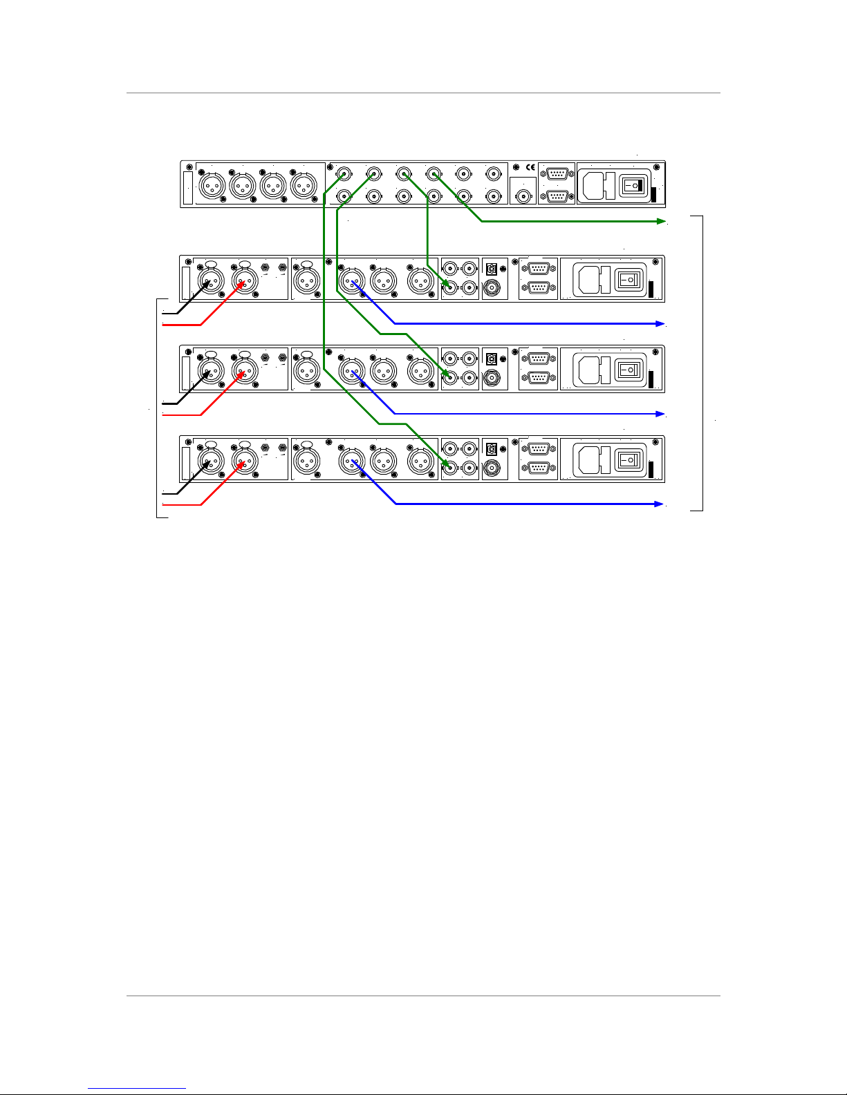
Six Channel Set Up Sync’ed to Master Clock (Word Clock)
Figure 8 - Six Channel Set Up Sync’ed to Master Clock (Word Clock)
do this: Set the dCS 992 Master Clock to the sample rate you wish to record at
and set the recorder to slave to it.
do this: For all 3 ADC’s, set A-SL (Autoslave) to On and select a filter. If you are
recording less than 24 bit words, set Word Length as required and set
Noise Shaping to Auto.
The Master Clock helps reduce jitter. This arrangement will work with one, two
or more ADC’s.
You can record from the SDIF-2 output or one of the SPDIF outputs if
preferred.
SPDIF
Reference In
AES/EBU
CH1(L)
Analogue Inputs
CH2(R)
CH1(L)
Sensitivity
CH2(R)
Output BOutput A
SDIF-2
CH1 CH2
CLK OutCLK In
Output C
Remote
See User Manual Before
Connecting To Supply
Serial No. On Underside.
Out
In
MAINS ON OFF
Before Removing Cover
Disconnect Mains
V 50/60Hz
FUSE (2AT)
PUSH PUSHPUSH
CH1
From analogue sources
dCS 900 / 902
CH2
AES 1 AES 2 AES 3 AES 4
AES/EBU Outputs
Wordclock Outputs
1 2 3 4 5 6
7 8 9 10 11 12
External
Sync
Remote
In
Loop
Out
Mains Fuse (2AT)
On Off
V 50-60Hz
Disconnect mains
before removing cover
dCS 992
SPDIF
Reference In
AES/EBU
CH1(L)
Analogue Inputs
CH2(R)
CH1(L)
Sensitivity
CH2(R)
Output BOutput A
SDIF-2
CH1 CH2
CLK OutCLK In
Output C
Remote
See User Manual Before
Connecting To Supply
Serial No. On Underside.
Out
In
MAINS ON OFF
Before Removing Cover
Disconnect Mains
V 50/60Hz
FUSE (2AT)
PUSH PUSHPUSH
CH3
dCS 900 / 902
CH4
SPDIF
Reference In
AES/EBU
CH1(L)
Analogue Inputs
CH2(R)
CH1(L)
Sensitivity
CH2(R)
Output BOutput A
SDIF-2
CH1 CH2
CLK OutCLK In
Output C
Remote
See User Manual Before
Connecting To Supply
Serial No. On Underside.
Out
In
MAINS ON OFF
Before Removing Cover
Disconnect Mains
V 50/60Hz
FUSE (2AT)
PUSH PUSHPUSH
CH5
dCS 900 / 902
CH6
CH1 & 2
CH3 & 4
Clock
To digital recorder
CH5 & 6
Word Clock
Page 28
dCS 900E / 902E User Manual Manual for Software Versions 1.3x to 1.5x
dCS Ltd 12th June 2000
Manual part no: DOC0029021E1 Page 28 Document No: OS-MA-D0002-902.1E1
Contact dCS on + 44 1799 531 999 email to: [email protected]
(inside the UK replace + 44 with 0) web site: www.dcsltd.co.uk
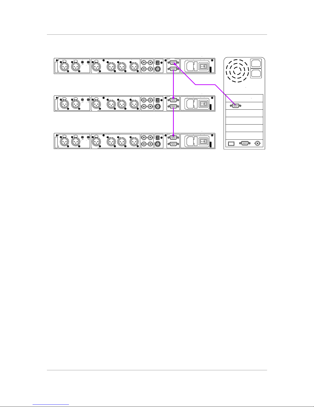
Operating Several Units on One Remote Chain
Figure 9 – Multi-unit Remote Daisy Chain
The PC can control several dCS units (up to about 5) of different types on each
daisy chain. To make them individually addressable, each unit needs its RS-232
address to be different. They can then be identified, and grouped, in the remote
window.
See “Remote In & Out“ on page 11 for cable details.
SPDIF
Reference In
AES/EBU
CH1(L)
Analogue Inputs
CH2(R)
CH1(L)
Sensitivity
CH2(R)
Output BOutput A
SDIF-2
CH1 CH2
CLK OutCLK In
Output C
Remote
See User Manual Before
Connecting To Supply
Serial No. On Underside.
Out
In
MAINS ON OFF
Before Removing Cover
Disconnect Mains
V 50/60Hz
FUSE (2AT)
PUSH PUSHPUSH
dCS 900 / 902
SPDIF
Reference In
AES/EBU
CH1(L)
Analogue Inputs
CH2(R)
CH1(L)
Sensitivity
CH2(R)
Output BOutput A
SDIF-2
CH1 CH2
CLK OutCLK In
Output C
Remote
See User Manual Before
Connecting To Supply
Serial No. On Underside.
Out
In
MAINS ON OFF
Before Removing Cover
Disconnect Mains
V 50/60Hz
FUSE (2AT)
PUSH PUSHPUSH
dCS 900 / 902
SPDIF
Reference In
AES/EBU
CH1(L)
Analogue Inputs
CH2(R)
CH1(L)
Sensitivity
CH2(R)
Output BOutput A
SDIF-2
CH1 CH2
CLK OutCLK In
Output C
Remote
See User Manual Before
Connecting To Supply
Serial No. On Underside.
Out
In
MAINS ON OFF
Before Removing Cover
Disconnect Mains
V 50/60Hz
FUSE (2AT)
PUSH PUSHPUSH
dCS 900 / 902
COM PORT
The Politically Correct
Computer Co.
Page 29
dCS 900E / 902E User Manual Manual for Software Versions 1.3x to 1.5x
dCS Ltd 12th June 2000
Manual part no: DOC0029021E1 Page 29 Document No: OS-MA-D0002-902.1E1
Contact dCS on + 44 1799 531 999 email to: [email protected]
(inside the UK replace + 44 with 0) web site: www.dcsltd.co.uk
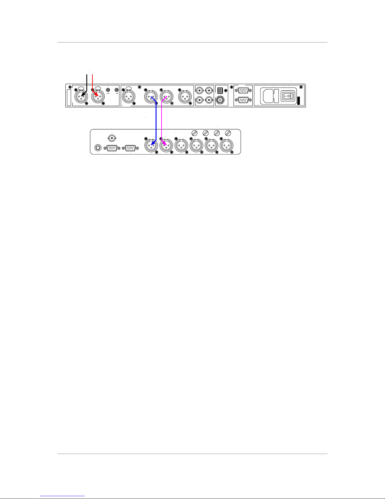
Recording Dual AES on a 4-Track Recorder
Figure 10 – Recording Dual AES on a 4-Track Recorder
do this: Set the dCS 902 to the sample rate you wish to record at (88.2 or 96kS/s)
and set the Output Format to 2. Set Ref In to Int and select a Filter. If
you are recording less than 24 bit words, set Word Length as required
and set Noise Shaping to Auto.
do this: Replay the tape through a Dual AES capable DAC such as dCS 952.
SPDIF
Reference In
AES/EBU
CH1(L)
Analogue Inputs
CH2(R)
CH1(L)
Sensitivity
CH2(R)
Output BOutput A
SDIF-2
CH1 CH2
CLK OutCLK In
Output C
Remote
See User Manual Before
Connecting To Supply
Serial No. On Underside.
Out
In
MAINS ON OFF
Before Removing Cover
Disconnect Mains
V 50/60Hz
FUSE (2AT)
PUSH PUSHPUSH
CH4CH3CH2CH1DIG3+4DIG1+2
INPUTS
RS-422ExtensionTimecode
Video
Sync In
L
R
From analogue
source
dCS 902
Dual AES
24 / 96
Digital Recorder
Page 30

dCS 900E / 902E User Manual Manual for Software Versions 1.3x to 1.5x
dCS Ltd 12th June 2000
Manual part no: DOC0029021E1 Page 30 Document No: OS-MA-D0002-902.1E1
Contact dCS on + 44 1799 531 999 email to: [email protected]
(inside the UK replace + 44 with 0) web site: www.dcsltd.co.uk
dCS 900 / 902 TECHNICAL INFORMATION
Anti Alias Filtering
The dCS 900 & 902 offer a choice of 4 anti-alias filters on most sample rates.
These filters affect the ultrasonic part of the spectrum - 20 kHz upwards.
The unit is an ADC, with an output data rate set by the interface standard used.
The bandwidth of the input stages and oversampling converter used is high, and
so any signals that that are in the input signal, up to a MHz or so, will be aliased
3
back into the output signal if they are not removed by filtering. The demands on
this anti-alias filter can be quite severe at the lower (“normal”) sample rates - it
must pass signals in the audio band (0-20 kHz) unimpaired, but it must prevent
aliasing about Fs/2. This can result in a very sharp filter, and it is an unavoidable
mathematical result that sharp filters have a poor, ringing, transient response.
One effect of the ringing is to spread the energy in a transient over a significant
period of time (it can be up to 1 ms). This seems to affect the stereo image that
the ear would otherwise form.
One can trade off filter roll-off, and energy smear - more relaxed roll-off gives
less energy smear, but it may allow some of the signals in the input to alias
irrevocably into the output data. Once a signal has aliased, it cannot be
corrected. However, as far as the ear is concerned, this may not matter. The
ear can tell the frequency of a signal - up to a point. As the frequency rises, the
accuracy with which the ear can tell what the frequency is decreases, and above
a limit, all the ear can tell is that there is a signal, and it is above ... kHz. It can
tell no more. So - it may be that some degree of aliasing is acceptable to the
ear.
The filters that we have included give increasingly good energy smear
performance, and consequently have increasingly relaxed roll off. FiLT1 gives
the sharpest roll off, with no aliasing, but the worst energy smear. Then as the
number increases the smear decreases, but the aliasing increases. Try them, to
see which you prefer.
You may find that for different material, different filters are appropriate - and you
may find that for different stages in the recording and mastering process,
different filters are appropriate.
The dCS 900 & 902 use linear phase FIR filters to avoid the limit cycle problems
that come with many IIR filters. Linear phase gives filters a symmetrical transient
response before and after a transient (“pre-ringing”). The passband may or may
not have a ripple4, depending on the filter being used. The stop band is typically
below –110 dB and can be as low as –130 dB.
3
See, for example “Principles of Digital Audio”, 3rd Edition, by Ken C Pohlmann (McGraw-Hill Inc, 1995)
4
Filters always have some ripple. For “zero ripple” filters this is in the µdB to pdB region.
Page 31

dCS 900E / 902E User Manual Manual for Software Versions 1.3x to 1.5x
dCS Ltd 12th June 2000
Manual part no: DOC0029021E1 Page 31 Document No: OS-MA-D0002-902.1E1
Contact dCS on + 44 1799 531 999 email to: [email protected]
(inside the UK replace + 44 with 0) web site: www.dcsltd.co.uk
Clocking
The sample clock quality significantly determines the output performance of an
ADC.
The highest quality clocks that are available are crystals, so we use these. In
Master mode, the dCS 900 & 902 use one of two on-board voltage controlled
crystal oscillators (VCXOs) as clock sources – one for 48 kS/s related outputs
and one for 44.1 kS/s related outputs. When an external clock is applied for
Slave operation, the internal VCXO is synchronised to this by a phase locked
loop (PLL). The PLL is of a special narrow bandwidth type, that provides a high
degree of "clock cleaning" - but even so, signal quality may degrade if
particularly poor slave clocks are used. A consequence of the narrow bandwidth
is that it takes quite a long time for the PLL to lock to a new clock frequency – of
the order of 2 seconds. The PLL uses DSP assistance to keep this time
acceptable.
Internal clock -
Accuracy when shipped ± 10 ppm
Long Term Stability ± 10 ppm/year at room temp.
Temperature Stability ± 15 ppm over operating temperature range
dCS 902 only: The VCXO frequency can be trimmed by using the Offst function
in the menu (see page 22) – each VCXO is independently adjustable
Synchronising to source -
Pull in range ± 300 ppm about nominal frequency
Lock in time < 2 seconds for most situations
The PLL is very robust, and will lock to very poor signals if necessary. Data is
decoded using a much wider band (faster) PLL, so AES3 type low frequency
jitter on the input clock can be handled, and will be cleaned.
If you need to synchronise several items of digital equipment, we recommend
using a dCS 992 Master Clock.
Page 32
dCS 900E / 902E User Manual Manual for Software Versions 1.3x to 1.5x
dCS Ltd 12th June 2000
Manual part no: DOC0029021E1 Page 32 Document No: OS-MA-D0002-902.1E1
Contact dCS on + 44 1799 531 999 email to: [email protected]
(inside the UK replace + 44 with 0) web site: www.dcsltd.co.uk
Sample Alignment
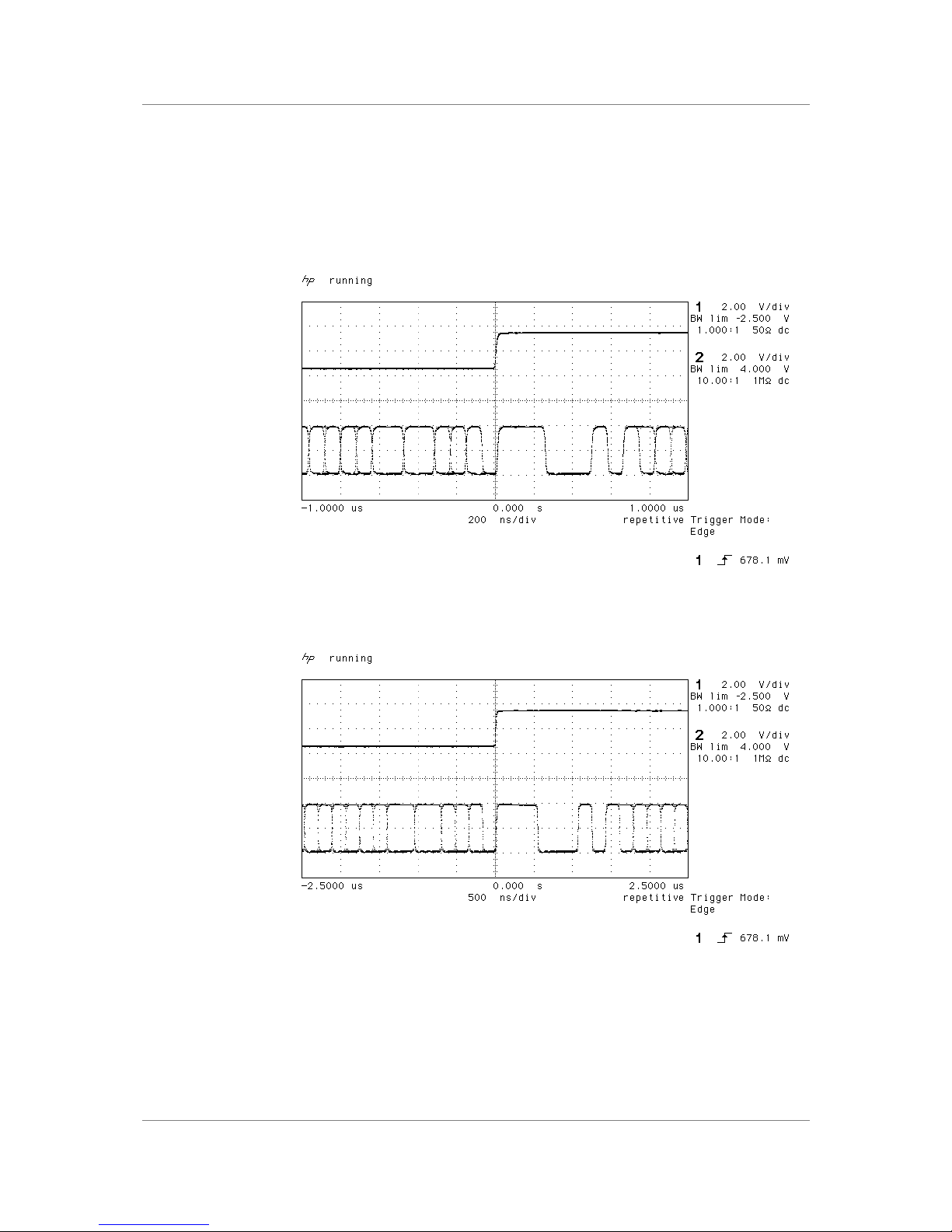
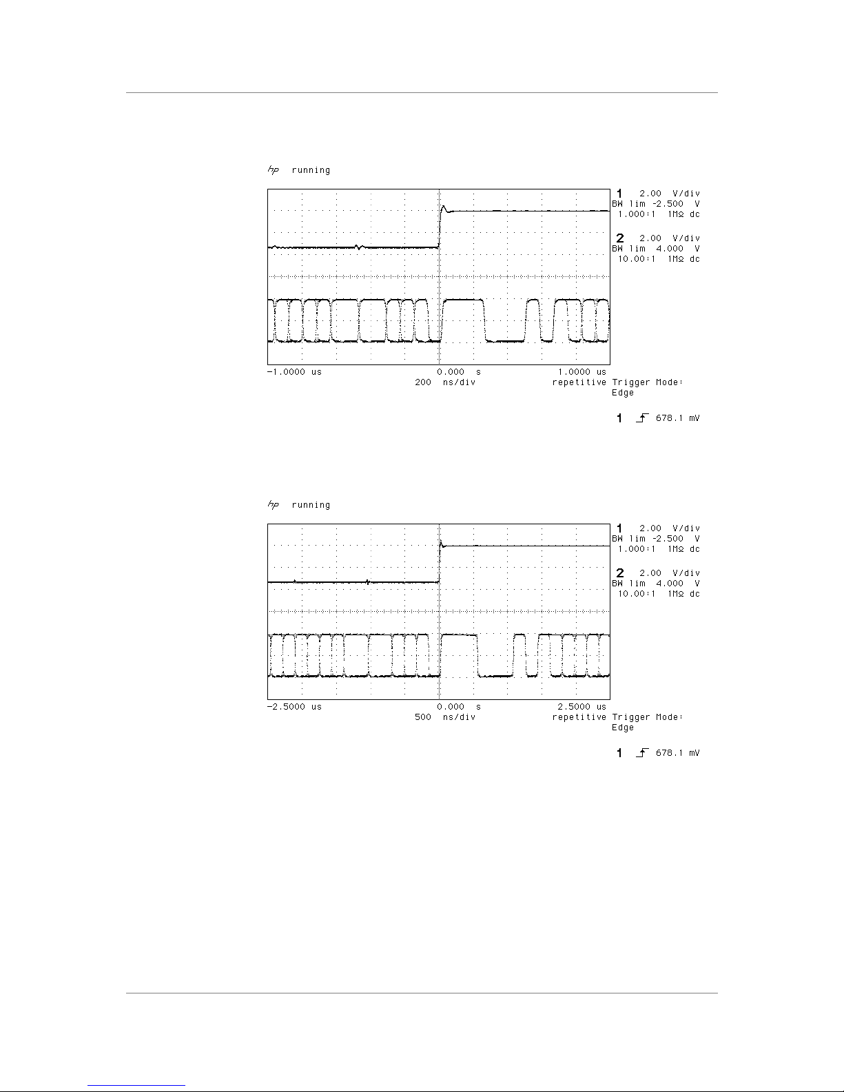
The dCS 900 & 902 align samples such that Word Clock out aligns with AES3
samples out, the rising edge of word clock aligning with the start of the first
illegal code in the X,Z subframe preamble and the falling edge aligning with the
start of the Y subframe preamble. The scope shots below were taken in Master
mode.
Figure 11 – Word Clock and AES3 outputs, 96 kS/s
Figure 12 – Word Clock and AES3 outputs, 44.1 kS/s
Page 33
dCS 900E / 902E User Manual Manual for Software Versions 1.3x to 1.5x
dCS Ltd 12th June 2000
Manual part no: DOC0029021E1 Page 33 Document No: OS-MA-D0002-902.1E1
Contact dCS on + 44 1799 531 999 email to: [email protected]
(inside the UK replace + 44 with 0) web site: www.dcsltd.co.uk
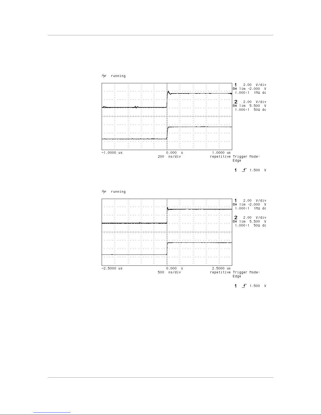
When Word Clock in is used as a sync source, in and out are related as below.
The lower waveform is the output, the upper one is the input. The misalignment
is less than about 40 nsecs. The scope shots below were taken with the unit
sync’d to Word Clock in.
Figure 13 – Word Clock in to Word Clock out, 96 kS/s
Figure 14 – Word Clock in to Word Clock out, 44.1 kS/s
Page 34
dCS 900E / 902E User Manual Manual for Software Versions 1.3x to 1.5x
dCS Ltd 12th June 2000
Manual part no: DOC0029021E1 Page 34 Document No: OS-MA-D0002-902.1E1
Contact dCS on + 44 1799 531 999 email to: [email protected]
(inside the UK replace + 44 with 0) web site: www.dcsltd.co.uk
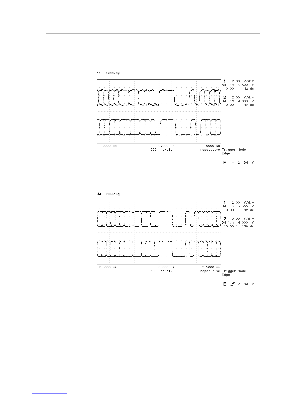
AES3 in and out are related as below, where they are at the same sample rate,
and the AES3 input is used as a sync source. The alignment is better than
40 nsecs. Input is at the top of the displays, output is at the bottom. Signals are
at the sockets on the dCS 900 & 902, and the unit was slaved to AES Ref In.
Figure 15 – AES3 in to AES3 out, 96 kS/s
Figure 16 – AES3 in to AES3 out, 44.1 kS/s
Page 35
dCS 900E / 902E User Manual Manual for Software Versions 1.3x to 1.5x
dCS Ltd 12th June 2000
Manual part no: DOC0029021E1 Page 35 Document No: OS-MA-D0002-902.1E1
Contact dCS on + 44 1799 531 999 email to: [email protected]
(inside the UK replace + 44 with 0) web site: www.dcsltd.co.uk
AES3 data out is also related to the phase of Word Clock in. The scope shots
below were taken with the unit sync’d to Word Clock.
Figure 17 – Word Clock in to AES3 out, 96 kS/s
Figure 18 – Word Clock in to AES3 out, 44.1 kS/s
Page 36

dCS 900E / 902E User Manual Manual for Software Versions 1.3x to 1.5x
dCS Ltd 12th June 2000
Manual part no: DOC0029021E1 Page 36 Document No: OS-MA-D0002-902.1E1
Contact dCS on + 44 1799 531 999 email to: [email protected]
(inside the UK replace + 44 with 0) web site: www.dcsltd.co.uk
Noise Shaping
The dCS 900 & 902 use noise shaping5 that is optimised to the F weighting
curve6. It does not affect signal frequency or transient response, but shapes the
frequency response of errors (Q noise, or truncation errors) so that they fall as
much as possible in the less sensitive part of the spectrum. For all the major
sample rates (32 kS/s, 44.1 kS/s, 48 kS/s, 88.2 kS/s, 96 kS/s) the noise shapers
have been individually optimised. The 1st, 3rd, and 9th shapes for 44.1 kS/s
agree well with Wannamaker’s published results7.
Noise Shaping adds more noise power, but because of the shaping it is
perceived as lower noise. There is a compromise to be drawn – as more
aggressive shaping is used, more noise is added, and less perceived
improvement occurs. In practice, things stop improving much above the 9
th
order. The increased real noise power can cause (small) clicks in editing, if this
is carried out after the shaping. For this reason, noise shaping should be used
as late as possible in the mastering process – we recommend recording at the
very highest possible sample rate and resolution, and only reducing either at the
latest possible minute.
If, however, you have to reduce word length, the perceived noise gain (taking
into account the ear’s response) and the actual increase in noise (mainly out of
band) in given in the table below.
Sample
Rate
(kS/s)
Perceived
Gain, F
weighted,
1st Order
(dB)
Actual
Increase
in Noise,
1st Order
(dB)
Perceived
Gain, F
weighted,
3rd Order
(dB)
Actual
Increase
in Noise,
3rd Order
(dB)
Perceived
Gain, F
weighted,
9th Order
(dB)
Actual
Increase
in Noise,
9th Order
(dB)
32 -3.3 1.9 -7.5 4.2 -8.1 6.1
44.1 -5.5 2.4 -10.5 6.9 -17.9 23.4
48 -6.2 2.5 -11.7 7.6 -21.0 23.8
88.2 -11.1 2.8 -23.8 11.3 -42.2 24.0
96 -11.8 2.9 -25.7 11.3 -45.3 22.5
176.4 -17.0 3.0 -40.6 12.6 -63.0 21.8
192 -17.7 3.0 -42.8 12.6 -65.9 21.8
Table 3 – Noise Shaper Gain by Order and Sample Rate
The 3rd order shaping tends to follow the E weighting curve, by chance. The 9
th
order is very aggressive, and can give very large gains at the higher sample
rates. For example, 176.4kS/s or 192kS/s material truncated to 16 bits (so it
can be stored on a DA-88 or ADAT) loses nothing in the audio band in terms of
perceived noise, with 3rd or 9th order shaping. For more information on this topic,
either see section “Word Length Reduction” on page 50 or read the
references below.
5
It actually uses an Error Shaping architecture, but the name is now being used for entirely other things and is
less well known, so we call it, erroneously, Noise Shaping
6
“Minimally Audible Noise Shaping”, S.P.Lipshitz and R.A.Wannamaker, J AES vol 39 no 11, p836-852
7
“Psychacoustically Optimal Noise Shaping”, R.A.Wannamaker, J AES vol 40 no 7/8, p611-620
Page 37
dCS 900E / 902E User Manual Manual for Software Versions 1.3x to 1.5x
dCS Ltd 12th June 2000
Manual part no: DOC0029021E1 Page 37 Document No: OS-MA-D0002-902.1E1
Contact dCS on + 44 1799 531 999 email to: [email protected]
(inside the UK replace + 44 with 0) web site: www.dcsltd.co.uk
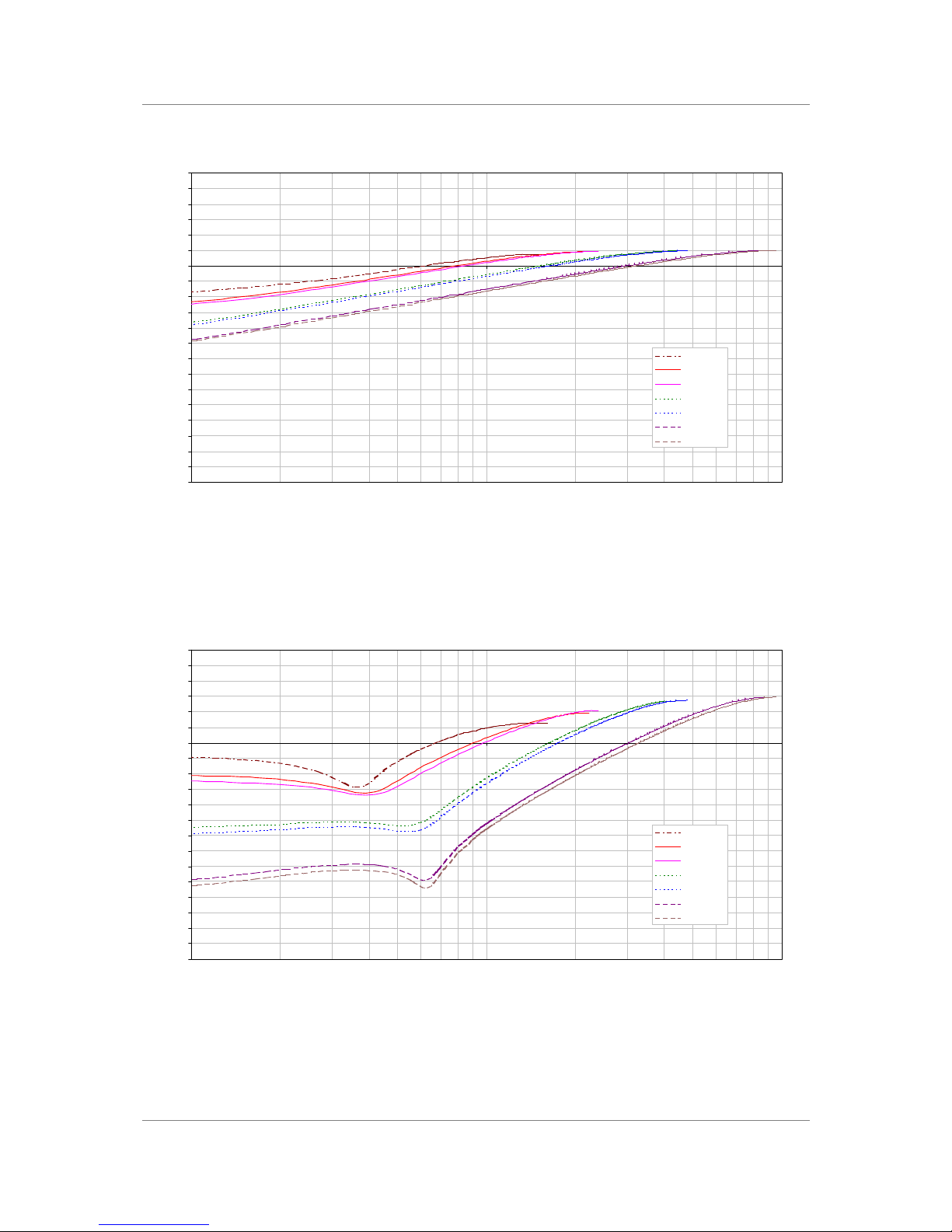
1st Order Noise Shape Plots
-84
-78
-72
-66
-60
-54
-48
-42
-36
-30
-24
-18
-12
-6
0
6
12
18
24
30
36
1 10 100
Frequency (kHz)
Noise Amplitude (dB)
32 kS/s
44.1 kS/s
48 kS/s
88.2 kS/s
96 kS/s
176.4 kS/s
192 kS/s
Figure 19 – 1st Order Noise Shapers implemented on dCS 90X
3rd Order Noise Shape Plots
-84
-78
-72
-66
-60
-54
-48
-42
-36
-30
-24
-18
-12
-6
0
6
12
18
24
30
36
1 10 100
Frequency (kHz)
Noise Amplitude (dB)
32 kS/s
44.1 kS/s
48 kS/s
88.2 kS/s
96 kS/s
176.4 kS/s
192 kS/s
Figure 20 – 3rd Order Noise Shapers implemented on dCS 90X
Page 38
dCS 900E / 902E User Manual Manual for Software Versions 1.3x to 1.5x
dCS Ltd 12th June 2000
Manual part no: DOC0029021E1 Page 38 Document No: OS-MA-D0002-902.1E1
Contact dCS on + 44 1799 531 999 email to: [email protected]
(inside the UK replace + 44 with 0) web site: www.dcsltd.co.uk
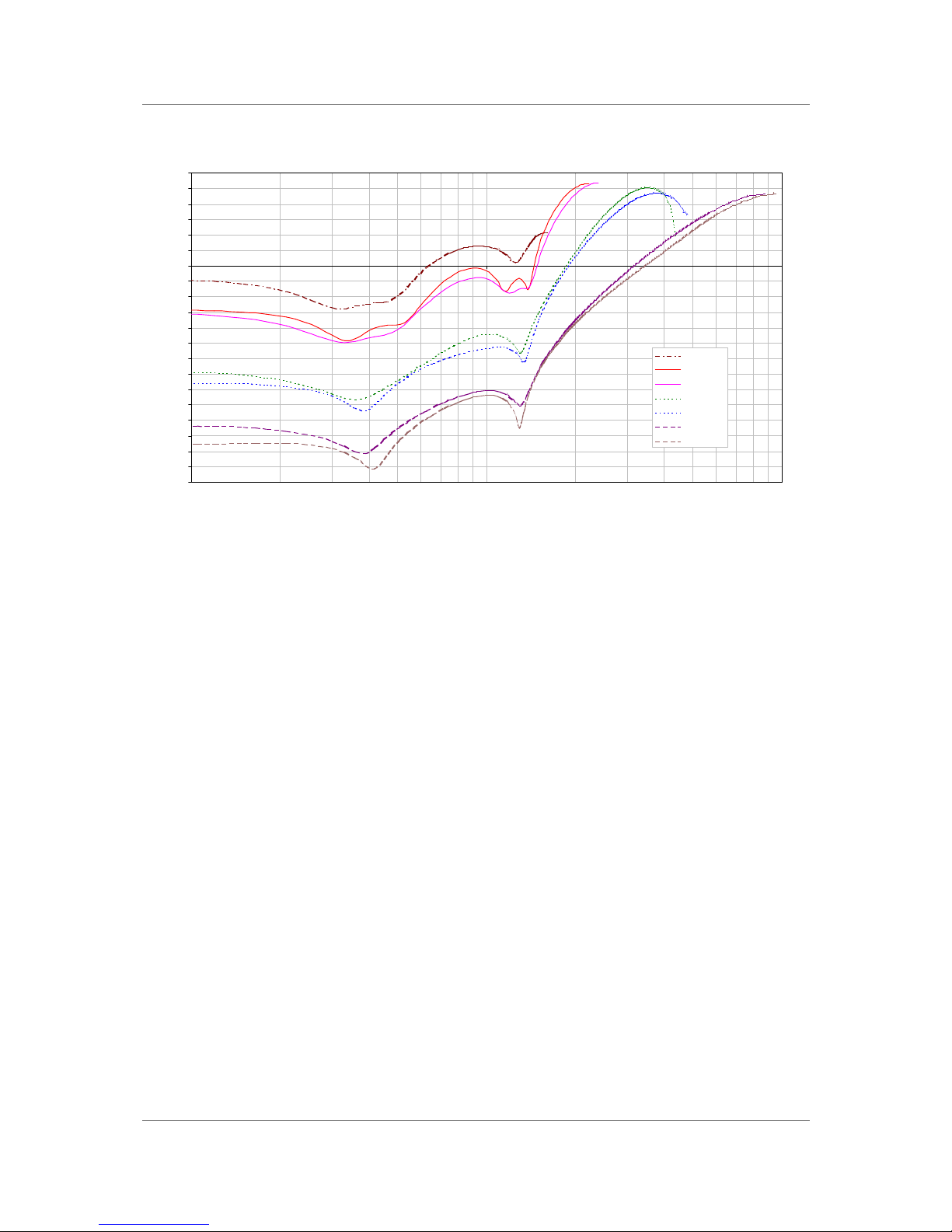
9th Order Noise Shape Plots
-84
-78
-72
-66
-60
-54
-48
-42
-36
-30
-24
-18
-12
-6
0
6
12
18
24
30
36
1 10 100
Frequency (kHz)
Noise Amplitude (dB)
32 kS/s
44.1 kS/s
48 kS/s
88.2 kS/s
96 kS/s
176.4 kS/s
192 kS/s
Figure 21 – 9th Order Noise Shapers implemented on dCS 90X
The noise shaper plots above are all on the same vertical scales for easy
comparison, and the vertical grid is approximately 1 bit per grid line. Note that
for the audio band, 9th order noise shaping at 176.4 kS/s or 192 kS/s gives huge
gains (8 bits or more).
This means that recording these formats on 8 channel 44.1 kS/s or 48 kS/s
recording machines that store only 16 bits is quite practical, and there is, in
practice, very little quality loss.
Page 39

dCS 900E / 902E User Manual Manual for Software Versions 1.3x to 1.5x
dCS Ltd 12th June 2000
Manual part no: DOC0029021E1 Page 39 Document No: OS-MA-D0002-902.1E1
Contact dCS on + 44 1799 531 999 email to: [email protected]
(inside the UK replace + 44 with 0) web site: www.dcsltd.co.uk
Digital Interface Specifications
AES/EBU (AES3)
Input Output
Type Balanced, differential
Impedance 110 110
Ω
Sensitivity (unloaded) 1 ~ 10 7 V pk-pk
Maximum Wordlength 24 24 bits
Damage level > 20 V pk-pk
Connector XLR3 female XLR3 male
Pin 1 Ground or shield
Pin 2 +Signal
Connections
Pin 3 -Signal
Table 4 – AES/EBU i/o specifications
SDIF-2
Input Output
Type Single ended, ground
referred
Impedance 100 25
Ω
Sensitivity (unloaded) TTL TTL
Maximum Wordlength 24 24 bits
Damage level > 10 V pk-pk
Time skew
Word Clock in / out < 40 ns
Connector BNC x 1 BNC x 3
CH1 (left)
CH2 (right)
Connections
Word Clock In & Out
Table 5 – SDIF-2 i/o specifications
SPDIF (electrical)
Output
Type Single ended, ground
referred
Impedance 75
Ω
Sensitivity (unloaded) 1.0 V pk-pk
Maximum Wordlength 24 bits
Damage level > 10 V pk-pk
Connector RCA Phono
Table 6 – SPDIF (electrical) output specifications
Page 40
dCS 900E / 902E User Manual Manual for Software Versions 1.3x to 1.5x
dCS Ltd 12th June 2000
Manual part no: DOC0029021E1 Page 40 Document No: OS-MA-D0002-902.1E1
Contact dCS on + 44 1799 531 999 email to: [email protected]
(inside the UK replace + 44 with 0) web site: www.dcsltd.co.uk
SPDIF optical)
Output
Type Optical
Maximum Wordlength 24 bits
Wavelength 660 nm
Connector Toslink EIAJ CP-340
Table 7 – SPDIF (optical) output specifications
Remote control interface
Input / Output
Type RS-232
Level RS-232
Data Format
Contact dCS
Connector 9 way D-type male
Table 8 - Remote Control Interface Details
Page 41

dCS 900E / 902E User Manual Manual for Software Versions 1.3x to 1.5x
dCS Ltd 12th June 2000
Manual part no: DOC0029021E1 Page 41 Document No: OS-MA-D0002-902.1E1
Contact dCS on + 44 1799 531 999 email to: [email protected]
(inside the UK replace + 44 with 0) web site: www.dcsltd.co.uk
Analogue Input Specifications
Balanced Inputs
Type Balanced
Format AES14 : 1992
Impedance + 5
kΩ
- 5
kΩ
CMRR 50 Hz >100 dB, spec
50 Hz >120 dB, typ
1 kHz >108 dB, typ
10 kHz >80 dB, typ
20 kHz >74 dB, typ
Level for Full Scale
(as shipped)
+20 dBu
Trim range ±6 dB
Connector type XLR3 female
Connections Pin 1 Ground or shield
Pin 2 +Signal
Pin 3 -Signal
Table 9 - Analogue XLR Interface Details
The analogue inputs are balanced (not floating) with a stable, high common
mode rejection ratio. Either input may be used on its own with the other floating
if single ended operation is wanted.
Page 42

dCS 900E / 902E User Manual Manual for Software Versions 1.3x to 1.5x
dCS Ltd 12th June 2000
Manual part no: DOC0029021E1 Page 42 Document No: OS-MA-D0002-902.1E1
Contact dCS on + 44 1799 531 999 email to: [email protected]
(inside the UK replace + 44 with 0) web site: www.dcsltd.co.uk
AES3 (AES/EBU) Format
Message Handling -
The AES/EBU interface transmits a data structure that conforms to the dCS
version of AES3-1992. This contains 28 bits of Manchester encoded data, and a
4 bit near-Manchester encoded preamble in a subframe, and subframes are
further assembled in a block and frame structure. Each subframe contains:
• preambles, to allow the receiver to sync up
• up to 24 bits of audio data, transmitted lsb first
• V, a validity bit
• U, a user bit, for the "User Message"
• C, a Channel Status bit, for the "System Message"
• P, a parity bit
IMPORTANT! The AES/EBU interface and the SPDIF interface have similar data
structures, although the messages are completely different. The two
structures are identified in the data domain by the use of the
Consumer/Professional bit (bit 1 in the message). A "1" indicates AES/EBU
format, a "0" indicates SPDIF format.
The default AES/EBU message attached to the output data by the unit before
being changed by the user is as follows:
Professional: On
Non-Audio: Off
Mode: Stereophonic
Source: DCS1
Destination: null
For more information on the way dCS implement the AES3 system message to
handle higher sample rates, see the Appendix to this manual. For the formal
definition of the AES3 interface, see footnote8, from the AES.
8
AES3-1992 (ANSI S4.40-1992) “AES Recommended practice for digital audio engineering – Serial
transmission format for two-channel linearly represented digital audio data”.
Page 43
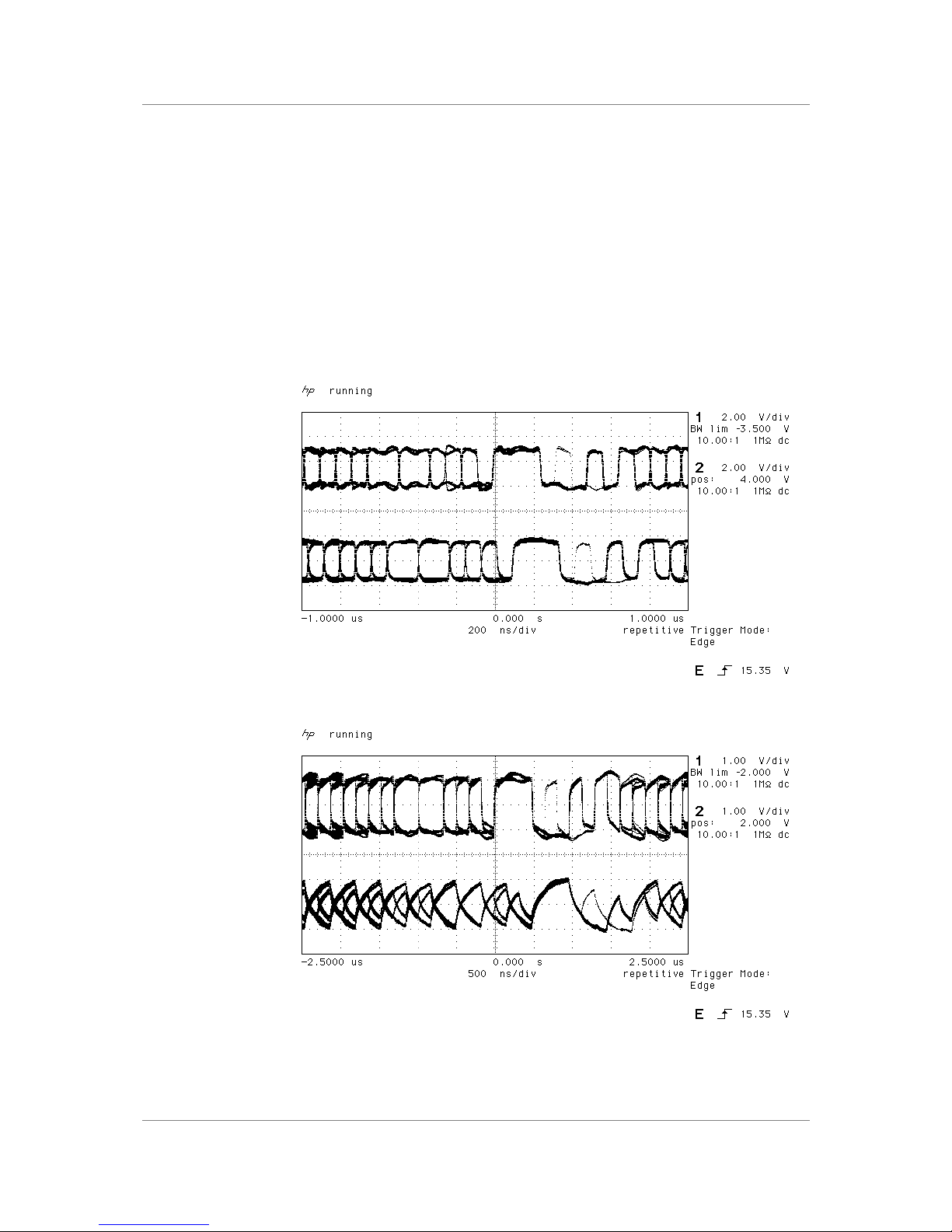
dCS 900E / 902E User Manual Manual for Software Versions 1.3x to 1.5x
dCS Ltd 12th June 2000
Manual part no: DOC0029021E1 Page 43 Document No: OS-MA-D0002-902.1E1
Contact dCS on + 44 1799 531 999 email to: [email protected]
(inside the UK replace + 44 with 0) web site: www.dcsltd.co.uk
How Far will it Go? -
The AES/EBU format was designed to go reasonable distances, at 44.1 kS/s
and 48 kS/s. Figure 22 and Figure 23 below show it over 16 m and 94 m using
average cables. The waveform at 94 m can still be decoded, although it is quite
degraded. Cable delay is about 5.6 nsecs/metre.
At 96 kS/s (twice the data rate the format was designed for) the allowed cable
length is less. Figure 24 and Figure 25 below show this over 16 m and 94 m. At
16 m the waveforms are still very good, but at 94 m they are really quite
unreliable.
We recommend restricting 96 kS/s cable runs to 20 m or less, and using good
cable near this length.
Figure 22 – AES3 format at 48 kS/s over 16 metres
Figure 23 – AES3 format at 48 kS/s over 94 metres
Page 44
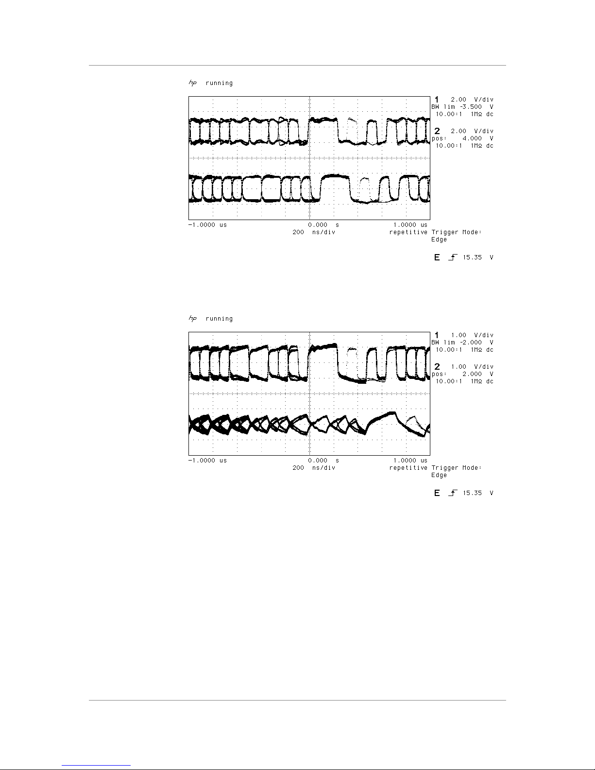
dCS 900E / 902E User Manual Manual for Software Versions 1.3x to 1.5x
dCS Ltd 12th June 2000
Manual part no: DOC0029021E1 Page 44 Document No: OS-MA-D0002-902.1E1
Contact dCS on + 44 1799 531 999 email to: [email protected]
(inside the UK replace + 44 with 0) web site: www.dcsltd.co.uk
Figure 24 – AES3 format at 96 kS/s over 16 metres
Figure 25 – AES3 format at 96 kS/s over 94 metres
Page 45

dCS 900E / 902E User Manual Manual for Software Versions 1.3x to 1.5x
dCS Ltd 12th June 2000
Manual part no: DOC0029021E1 Page 45 Document No: OS-MA-D0002-902.1E1
Contact dCS on + 44 1799 531 999 email to: [email protected]
(inside the UK replace + 44 with 0) web site: www.dcsltd.co.uk
SPDIF
Message Handling -
The SPDIF interface (sometimes known as the Consumer AES/EBU interface)
transmits a data structure that conforms to the IEC 9589 standard. Like the
AES/EBU, this contains 28 bits of Manchester encoded data, and a 4 bit nearManchester encoded preamble in a subframe, and subframes are further
assembled in a block and frame structure. The difference lies only in the
voltage levels, and the Channel Status bits (the System Message). It contains
24 bits of audio data.
IMPORTANT! The AES/EBU interface and the SPDIF interface have similar data
structures, although the messages are completely different. The two
structures are identified in the data domain by the use of the
Consumer/Professional bit (bit 1 in the message). A "1" indicates AES/EBU
format, a "0" indicates SPDIF format.
The default SPDIF message attached to the output data by the unit before being
changed by the user is as follows:
Professional: Off
Non-Audio: Off
Copy Permit: On
Format: 2-Channel General Format
9
See EN 60958:1995 or IEC958:1989 with amendments 1 & 2. The structure of the message is sufficiently
complex that it is best to read the source material.
Page 46
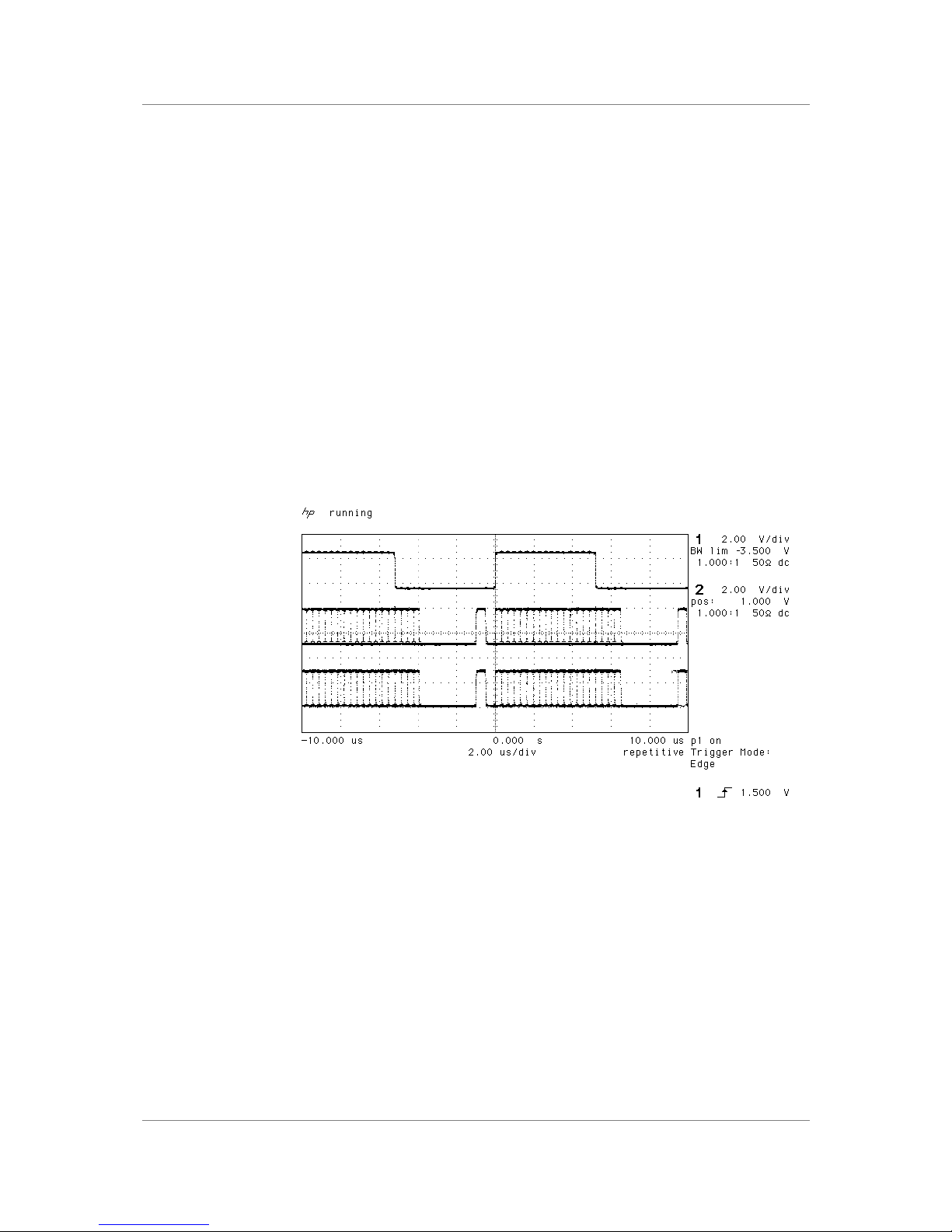
dCS 900E / 902E User Manual Manual for Software Versions 1.3x to 1.5x
dCS Ltd 12th June 2000
Manual part no: DOC0029021E1 Page 46 Document No: OS-MA-D0002-902.1E1
Contact dCS on + 44 1799 531 999 email to: [email protected]
(inside the UK replace + 44 with 0) web site: www.dcsltd.co.uk
SDIF-2
PCM Format -
The SDIF-2 interface is a 4 wire NRZ interface - so the DC level on each signal
line may not be constant. It contains 20 bits of audio data and has a block
structure of 256 stereo samples, rather than the 192 of AES/EBU. There are 8
bits of message per channel per sample - with a further 3 bits being used for an
"illegal code" based sync code. Of the 8 bits per sample, the 8 in the first sample
are reserved for system messaging, and the rest are for User messages.
The 4 wires are:
Ground return
Left Channel
Right Channel
Word Clock
The sync codes can enable data recovery without the word clock, if necessary,
but with the number of data formats in current operation, this method of locking
is strongly discouraged. The waveforms below are SDIF-2 waveforms (data and
word clock) at 96kS/s and 44.1kS/s.
Figure 26 – SDIF-2 PCM format at 96 kS/s
Page 47
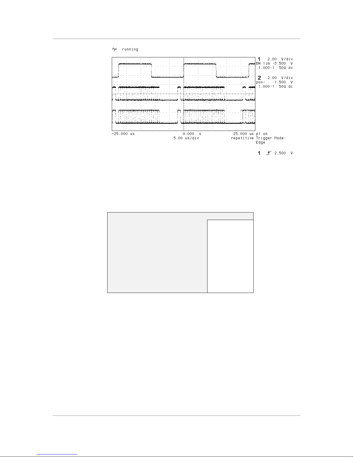
dCS 900E / 902E User Manual Manual for Software Versions 1.3x to 1.5x
dCS Ltd 12th June 2000
Manual part no: DOC0029021E1 Page 47 Document No: OS-MA-D0002-902.1E1
Contact dCS on + 44 1799 531 999 email to: [email protected]
(inside the UK replace + 44 with 0) web site: www.dcsltd.co.uk
Figure 27 – SDIF-2 PCM format at 44.1 kS/s
SDIF-2 Messaging -
The SDIF-2 message is given in the table following. The dCS 900 & 902
implementation sets all bits of the User message to "0".
DESCRIPTION Definition
Undefined 0000 0xxx
Emphasis
No emphasis
Emphasis (15µsec, 50µsec)
xxxx x00x
xxxx x01x
Dubbing Prohibit
Dubbing allowed
Dubbing inhibited
xxxx xxx0
xxxx xxx1
Block Code
Start of block
Not start of block
xxxx xxxx 1...
xxxx xxxx 0...
Table 10 – SDIF-2 Message Table
Page 48

dCS 900E / 902E User Manual Manual for Software Versions 1.3x to 1.5x
dCS Ltd 12th June 2000
Manual part no: DOC0029021E1 Page 48 Document No: OS-MA-D0002-902.1E1
Contact dCS on + 44 1799 531 999 email to: [email protected]
(inside the UK replace + 44 with 0) web site: www.dcsltd.co.uk
Power Consumption
The dCS 900 & 902 have a linear power supply, and so power consumption
changes as the mains voltage changes. The internal regulation is comparatively
efficient for a linear supply, so these changes are kept to a minimum.
Consumption is independent of mains voltage selector switch setting.
Power Consumption with Mains Voltage (measured as AC power into mains
socket):
Nominal mains 25 W
Mains -10% 22 W
Mains +10% 27 W
The actual intended supply voltage is shown on the rear panel. 50Hz or 60Hz
operation is not important – the unit can use either. In general, users will not
need to change the mains input configuration. If you do need this to be done,
please see the section "Having Your Options Changed”, page 54 in this
manual and contact your distributor or dCS.
Page 49

dCS 900E / 902E User Manual Manual for Software Versions 1.3x to 1.5x
dCS Ltd 12th June 2000
Manual part no: DOC0029021E1 Page 49 Document No: OS-MA-D0002-902.1E1
Contact dCS on + 44 1799 531 999 email to: [email protected]
(inside the UK replace + 44 with 0) web site: www.dcsltd.co.uk
Size, Weight and Operating Conditions
Size and Weight -
The dCS 900 & 902 dimensions correspond to a standard 2U 19" rack mount
case. Four heavy duty feet, fitted to the base, extend the overall height to
slightly greater than 2U.
Dimensions
Width 430 mm see note (i)
Height, without feet 44 mm (2U)
Height, with feet 52 mm
Depth 390 mm see note (ii)
Weight 6.8 kg see note (iii)
note (i) Removable 19" rack mount ears are supplied,
taking total width to 483 mm (19").
note (ii) Measured from front panel to rear panel
connectors. Additional depth should be allowed to
accommodate cable connectors.
note (iii) The high quality case is necessarily heavy,
consideration should be paid to appropriate support
shelving when installing the units in a rack.
Operating Conditions -
The case of the dCS 900 & 902 have no ventilation slots or fan cooling, to give:
• quiet operation (does not need to be installed in a machine room)
• internal temperature stability
• improved electrical safety
• long term reliability
• no regular maintenance or cleaning requirements
It dissipates relatively low power, so that usually allowing natural convection
provides enough cooling. Do not install the unit near heat sources such as
radiators, air ducts or direct strong sunlight. Ambient should not exceed 50°C,
should not fall below 0°C, and should be a non condensing. If in doubt, the easy
test is – the dCS 900 & 902 are happy to work anywhere a human is.
Page 50

dCS 900E / 902E User Manual Manual for Software Versions 1.3x to 1.5x
dCS Ltd 12th June 2000
Manual part no: DOC0029021E1 Page 50 Document No: OS-MA-D0002-902.1E1
Contact dCS on + 44 1799 531 999 email to: [email protected]
(inside the UK replace + 44 with 0) web site: www.dcsltd.co.uk
GENERAL TECHNICAL INFORMATION
Word Length Reduction
Word length reduction (truncation) causes an error signal to be added to the
wanted signal. The error signal is usually referred to as “Q noise” or
Quantisation noise – the approximation is usually made that the errors are noise
like. This is reasonably true for large signals, where the errors are very complex
if they are not exactly noise like. Importantly, though, for smaller ones it is not
so. As the wanted signal gets smaller, the complexity of the error signal
decreases. The errors first of all pile into ever fewer lower order harmonics or
intermodulation products, and then, as the level of the signal sinks below the Q
level, the majority of the error power piles into the signal fundamental. This
causes its amplitude to become unpredictable – it may drop abruptly to zero and
disappear, or it may cease to go down any more and just stay at a constant
level. From the audio viewpoint, this sounds very unpleasant. As a signal tail
decays away, the tonal quality changes, and then it decays into distorted mush
and then either abruptly stops, or else keeps fuzzing away until a new signal
starts. The level at which all this happens is the lsb of the output word – for CDs,
it is at the 16 bit level, which equates to about -90 dB0. This level is high
enough to be quite audible, and the effect must be tackled to make reasonable
quality end product.
There is really only one way of tackling the problem – another signal has to be
added to the wanted one to smooth the staircase transfer function that
truncation causes. Mathematically, with two signals present, the transfer function
that the wanted signal sees is the convolution of the PDF10 of the second signal
and the staircase function. The converse is also true – the transfer function the
additional signal sees is the convolution of the PDF of the wanted signal and the
staircase function. This aspect is not a problem with the dither types considered
below, but it can be with some highly frequency shaped dithers.
The trick is to make the second signal as inaudible as possible. It is usually
referred to as dither, and it is usually noise like, because then its statistics can
be controlled, and the converse effect of the signal modulating the dither can be
made insignificant, or zero. However, there are a number of ways that this dither
signal can be generated and treated. The major options are:
• generate it from the signal or generate it independently and add it (“Dither”).
It seems implausible that the dither signal can be generated from the signal,
but it can, and this gives the lowest added noise power option. It is noise
shaping on its own, but there are some circumstances where it needs help
from additional dither.
• add inside or outside an error shaping loop.
• frequency shape to match the ears response or not. One can use
techniques that suppress error energy in the areas where the ear is
sensitive, and put it in areas where the ear is not sensitive. Usually this
shuffling around process costs something – we remove a little from the
sensitive areas and add back rather more in the less sensitive parts, but
that’s life. We still gain some improvements.
The table below gives the actual noise levels for 16 bit truncated signals with no
dither, various types of dither, noise shaping on its own, and noise shaping with
dither. The 0 dB reference level is taken as the minimum noise we could
possibly get away with – the amount that simple 16 bit truncation (16 bit Q noise)
would give, if it were well behaved, which it is not.
10
PDF = Probability Distribution Function. References to Rectangular Dither or Triangular Dither refer the
shape of the PDF of the dither.
Page 51

dCS 900E / 902E User Manual Manual for Software Versions 1.3x to 1.5x
dCS Ltd 12th June 2000
Manual part no: DOC0029021E1 Page 51 Document No: OS-MA-D0002-902.1E1
Contact dCS on + 44 1799 531 999 email to: [email protected]
(inside the UK replace + 44 with 0) web site: www.dcsltd.co.uk
Straight forward dither always adds noise – it can only produce signals with a
noise floor higher than Q noise on its own. However, the noise power added is
a few dBs for simple types. Noise shaping adds rather more noise, but it can be
made to add it in parts of the spectrum that the ear is less sensitive to, so the
perceived noise (F weighted noise) is lower – up to three bits lower. It results in
a signal that the ear hears as having a far lower noise floor than a 16 bit
truncated signal, rather than the “not much worse” of dither alone, even though
there is really more noise present11.
Truncation Type, with
44.1 kS/s data rate
Noise,
unweighted,
rel 16 bit Q
noise
12
Noise,
F weighted,
rel 16 bit Q
noise
Comments
16 bit truncation 0 dB 0 dB Unpleasant low
level effects
16 bit truncation with
Top Hat dither
3 dB 3 dB Okay – can show
noise modulation at
low signal levels
16 bit truncation with
Triangular dither
4.8 dB 4.8 dB All noise
modulation and
unpleasant effects
removed, but noise
floor is high
16 bit truncation with
Noise Shaped
Triangular dither
4.8 dB 1.2 dB All noise
modulation and
unpleasant effects
removed. Not much
perceived noise
penalty
16 bit truncation with 3
rd
order noise shaping and
no dither
6.9 dB -10.5 dB Okay with input
noise floors down to
–102 dB
16 bit truncation with 3
rd
order noise shaping and
Noise Shaped
Triangular dither
11.0 dB -9.2 dB Unconditionally free
from truncation
effects with all
inputs
16 bit truncation with 9
th
order noise shaping and
no dither
23.4 dB -17.9 dB Okay with input
noise floors down to
–120 dB
16 bit truncation with 9
th
order noise shaping and
Noise Shaped
Triangular dither
28.2 dB -16.7 dB Unconditionally free
from truncation
effects with all
inputs
Table 11 – Dither and Noise Shaping Noise Powers
Noise shaping on its own is not perfect. It relies on a small amount of noise in
the input signal to generate the frequency shaped correction signal, and if there
is very low noise in the input signal, this mechanism can break down. With
ADCs, however, this situation does not arise, because of the analogue noise in
the ADC and the input signal.
11
DSD carries this further. The principle is the same, but with DSD, there is more noise than there is signal,
even at full scale. It is just that it is in a part of the spectrum the ear cannot hear.
12
16 bit Q noise is -98.1 dB relative to a full scale sine wave.
Page 52
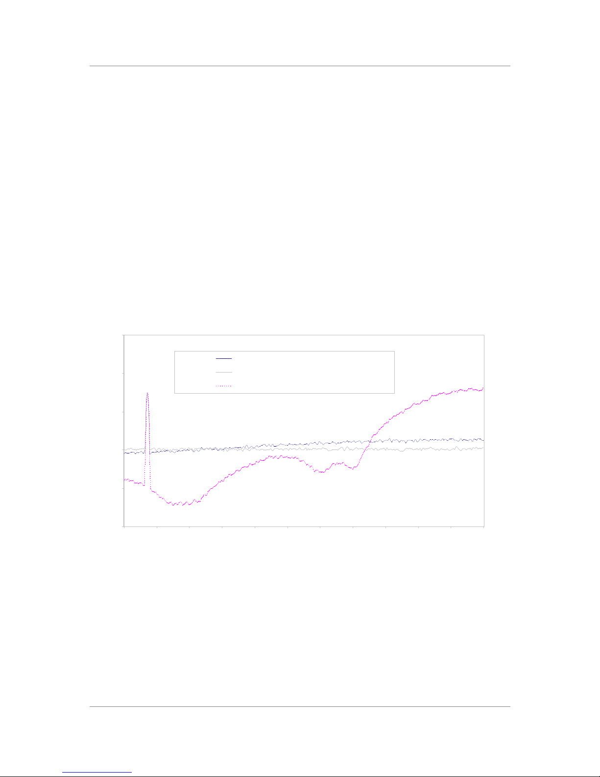
dCS 900E / 902E User Manual Manual for Software Versions 1.3x to 1.5x
dCS Ltd 12th June 2000
Manual part no: DOC0029021E1 Page 52 Document No: OS-MA-D0002-902.1E1
Contact dCS on + 44 1799 531 999 email to: [email protected]
(inside the UK replace + 44 with 0) web site: www.dcsltd.co.uk
There is another option not supported by the dCS 900 & 902 – generate the dither
independently of the signal and frequency shape it prior to addition, but do not
add it in an error shaping loop. This seems to dCS to combine the worst of all
worlds – the high noise floor in the 0-6 kHz area of straight dither, and the high
total noise of noise shaping. However, some people use it.
What does it look like? -
Figure 28 gives the spectra of 16 bit truncated 44.1 kS/s signals with a –90dB
sine present, for two dither only signals (Top Hat, Noise Shaped Triangular), and
with a 10th order noise shaped13 signal, generated and processed by a dCS 972.
The equivalent simply truncated spectrum is shown in Figure 29, separately
because it is so revolting. In it, we can see that at the signal level shown
(-90 dB) error power from the quantising/truncation is beginning to pile into the
fundamental, which is showing an amplitude error of +1.3 dB, as well as all the
unwanted harmonics. This would show up on a conventional linearity plot,
although the sign of the error could be either way.
We see that the noise shaping approach maintains low noise in the critical audio
mid band.
Noise Shaper and Dither Only Comparison
dCS 972 SW v1.54
-160
-140
-120
-100
-80
-60
0 2 4 6 8 10 12 14 16 18 20 22
Frequency (kHz)
Amplitude, Real Data (dB)
16 bit truncation, Noise Shaped Triangular dither
16 bit truncation, Top Hat dither
16 bit truncation, high order noise shaping only
44.1 kS/s sampling, 1024 point FFTs, H6 window, -90 dB 1.44 kHz input
Figure 28 – Noise Shaping and Dither Spectra
13
for comparison with the table, 10th and 9th order noise shaping are very similar.
Page 53
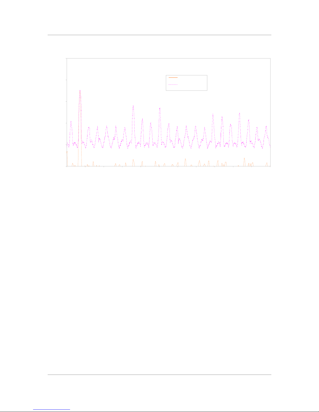
dCS 900E / 902E User Manual Manual for Software Versions 1.3x to 1.5x
dCS Ltd 12th June 2000
Manual part no: DOC0029021E1 Page 53 Document No: OS-MA-D0002-902.1E1
Contact dCS on + 44 1799 531 999 email to: [email protected]
(inside the UK replace + 44 with 0) web site: www.dcsltd.co.uk
Spectra of -90dB 24 bit sinewave truncated to 16 bits with dither options
dCS 972 SW v1.54
-91.00 dB source signal
-89.70 dB 16 bit truncated
-160
-140
-120
-100
-80
-60
0 2 4 6 8 10 12 14 16 18 20 22
Frequency (kHz)
Amplitude (dB)
24 bit source data
16 bit truncation, no
dither
44.1 kS/s sampling, 1.44 kHz input, 1024
point FFTs, H6 Window
Figure 29 – Truncation Only Spectra
Page 54

dCS 900E / 902E User Manual Manual for Software Versions 1.3x to 1.5x
dCS Ltd 12th June 2000
Manual part no: DOC0029021E1 Page 54 Document No: OS-MA-D0002-902.1E1
Contact dCS on + 44 1799 531 999 email to: [email protected]
(inside the UK replace + 44 with 0) web site: www.dcsltd.co.uk
OPTIONS
Mains Voltage
We ship with the mains wired according to the destination. The voltage option
should be specified when the unit is ordered, by specifying the country of use. It
can be updated later by your dealer, if necessary.
Video Frequency VCXOs
We can fit additional video frequency VCXOs (enabling frequencies such as
44.056 kS/s and 47.952 kS/s). These must be fitted at dCS, to allow full
checking.
P3D, DSD Pro and Other Formats
We can fit larger FPGAs to allow P3D, DSD Pro and other formats. This has to
be done at dCS.
Ordering Options For A New Unit
To order any option, just tell us:
dCS 900 for use in <country>, with options ….
or
dCS 902 for use in <country>, with options ….
IMPORTANT! Always specify the intended country of operation, otherwise we will assume
that country of delivery is the same as country of operation.
Having Your Options Changed
dCS support modifications, updates and option changes to supplied dCS 900 &
902 units. If you are in any doubt, please contact your Distributor or dCS. In
general, these will be carried out at dCS, because we have extensive test
facilities and can verify the changes.
IMPORTANT! Please do not attempt the changes yourself. The unit's performance and
reliability may be impaired, and the warranty will be invalidated.
Page 55

dCS 900E / 902E User Manual Manual for Software Versions 1.3x to 1.5x
dCS Ltd 12th June 2000
Manual part no: DOC0029021E1 Page 55 Document No: OS-MA-D0002-902.1E1
Contact dCS on + 44 1799 531 999 email to: [email protected]
(inside the UK replace + 44 with 0) web site: www.dcsltd.co.uk
Page 56
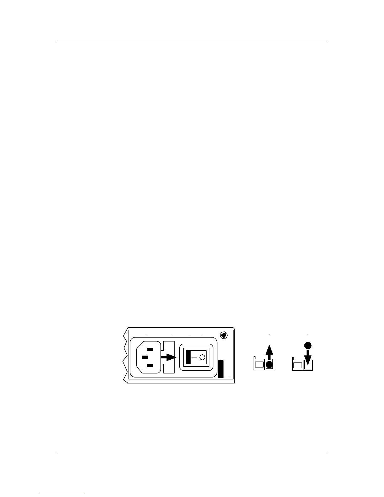
dCS 900E / 902E User Manual Manual for Software Versions 1.3x to 1.5x
dCS Ltd 12th June 2000
Manual part no: DOC0029021E1 Page 56 Document No: OS-MA-D0002-902.1E1
Contact dCS on + 44 1799 531 999 email to: [email protected]
(inside the UK replace + 44 with 0) web site: www.dcsltd.co.uk
MAINTENANCE AND SUPPORT
Hardware
Service & Maintenance
dCS audio products are designed not to need regular maintenance, and contain
no user serviceable parts:
• there are no moving parts,
• there are no short life or wear-out parts used,
• the units have no holes through which liquids or
• contamination can normally enter,
• no dust deposits build up to degrade performance.
All parts are replaceable or upgradeable by dCS, for a period of at least five
years from the date you purchased your unit. If your unit is damaged in some
way, please contact your Distributor or dCS.
User Changeable Parts
There are no user serviceable parts inside the case. Routine maintenance is
not necessary and repairs are generally carried out by dCS, since this allows us
to thoroughly verify the results before shipment.
There is a mains fuse in the mains socket, accessible from the outside of the
unit. This may be changed by the user. The current consumption of the unit is
very low (150 mA at 110 V) so it only blows if there is a fault - usually if the unit
is set to its low voltage setting (100 - 120V) but has been plugged into a high
voltage mains (220 - 240V). Usually no other damage is caused, but if the fuse
blows repeatedly on replacement, some other damage will have been done and
the unit must be returned to dCS for repair.
Fuse Type : 20 x 5mm 2 amp HRC fuse
If the fuse should fail, it is essential that it be replaced with one of the same type.
Failure to do so could result in damage to the unit and may invalidate the
guarantee. To gain access to the fuse, remove the IEC mains connector, use a
small flat bladed screwdriver to pry up the tab on the fuse carrier and pull it out.
Push the fuse out of the clip in the carrier and replace it with a new one. Push
the carrier back into the unit so that it clicks home.
MAINS FUSE 2A(T) ON OFF
Disconnect mains
before removing cover
V 50-60Hz
Remove
old fuse
Fit
new fuse
Figure 30 – Changing the Mains Fuse
IMPORTANT! Disconnect from the mains before changing the fuse.
Page 57

dCS 900E / 902E User Manual Manual for Software Versions 1.3x to 1.5x
dCS Ltd 12th June 2000
Manual part no: DOC0029021E1 Page 57 Document No: OS-MA-D0002-902.1E1
Contact dCS on + 44 1799 531 999 email to: [email protected]
(inside the UK replace + 44 with 0) web site: www.dcsltd.co.uk
Software
Installing New Software
The operating software can be downloaded via the RS-232 link from a PC com
port, using the Windows Remote software running on the PC.
To use this, follow the installation instructions on the floppy discs the remote
software is supplied on. Then, run the remote programme, with whatever units
you want connected. The software will scan the RS-232 chain for units (this
takes a while) to see what is connected. It then reports back and for each there
is an info button. This gives you the option of installing new software in that unit.
To find out if there are any software updates available for your equipment, call
us, or email us, with your unit’s serial number.
Hardware Update or Calibration
You may wish to have your unit updated occasionally. dCS offer this service - we
will install any modifications or updates that have occurred since your unit was
first shipped, and give the unit a full retest to current standards. The price will
depend on the hardware changes necessary – so contact your dealer or us. In
order to ensure speedy turn around please contact us prior to returning the unit.
Safety and Electrical Safety
There are no user serviceable parts inside the dCS 900 & 902 and so there is no
need to remove the covers, apart from front panel software updates. If for some
reason you do:
IMPORTANT! Disconnect from the mains before removing any covers or changing the fuse.
There are no substances hazardous to health inside the dCS 900 & 902.
Page 58

dCS 900E / 902E User Manual Manual for Software Versions 1.3x to 1.5x
dCS Ltd 12th June 2000
Manual part no: DOC0029021E1 Page 58 Document No: OS-MA-D0002-902.1E1
Contact dCS on + 44 1799 531 999 email to: [email protected]
(inside the UK replace + 44 with 0) web site: www.dcsltd.co.uk
TROUBLESHOOTING
Error Codes and Messages
The error codes reported by dCS 900 & 902 provide an effective means to
diagnose the majority of problems that may be encountered in use - including
problems with the overall system the unit operates in, internal device warnings
and internal device failures. Please note that through damage or component
failure, the unit self check may fail to operate. If this happens, please contact
your distributor or dCS for assistance.
Internal Device Error Codes
Sometimes the unit may misbehave. If there is an internal reason, an internal
device error code may be displayed as follows:
Err.xy an error xy (see table below) has been detected
where xy values have the following meanings:
Code Description
01 E2 memory (EEPROM) not present
02 Error initialising DSP
03 Error loading DSP
04 Error initialising DSP for coefficients
05 Error initialising DSP for coefficients
06 Error loading DSP coefficients
07 Error loading DSP coefficients
08 Error sending command
09 Error sending command
10 Error sending command
11 Error sending command
12 Error with LSB/MSB configuration
13 Error with LSB/MSB configuration
14 Error with LSB/MSB configuration
15 Error configuring FPGA
99 DSP error
Table 12 - Internal Error Codes
If you get any of these, please contact dCS, with as much information as
possible to help us re-create the problem. Some of these may have hardware
problems as their cause, some may have software.
Page 59

dCS 900E / 902E User Manual Manual for Software Versions 1.3x to 1.5x
dCS Ltd 12th June 2000
Manual part no: DOC0029021E1 Page 59 Document No: OS-MA-D0002-902.1E1
Contact dCS on + 44 1799 531 999 email to: [email protected]
(inside the UK replace + 44 with 0) web site: www.dcsltd.co.uk
System Messages and Error Codes
Some other messages may be displayed that give indications of errors from
other sources (outside the unit):
Display Description
n.Aud The data has been flagged by an AES3 message as non
audio (perhaps a CD ROM). This message may also be
displayed briefly when the sample sample rate is changed.
Hot The unit is overheating, and performance may suffer.
Ouch The unit is seriously overheating, and may be damaged
shortly. Switch off!
Bad Fs The sample rate coming in is not one the unit can lock to,
or there is an input signal quality problem.
Table 13 - System Error Codes
Trouble Shooting Your System
If you experience difficulties when using your dCS 900 / 902, the following
suggestions may help to resolve the problem.
The unit fails to power up -
• Ensure there is power available on the mains cable and the unit’s mains
switch is On.
• Check the rated supply voltage shown on the rear of the unit matches the
local supply voltage.
• Check that the fuse has not blown - if so, correct any obvious cause then
replace the fuse as described in the section “User Changeable Parts”,
page 56.
• Check that the mains cable is pushed fully home into the mains inlet in the
rear of the unit.
The audio output is low or absent -
• Check that all cables are connected correctly and not damaged. Damaged
cables are a VERY common source of malfunctions!
• Check that the source and destination equipment are switched on and
correctly set up.
• Check that an audio signal is present on one or both of the inputs.
• Ensure Mute is not enabled - LED off.
The level trimmers on the rear panel do not change the input level
• Ensure the trim tool or screwdriver you are using is narrow enough to reach
the adjuster (about 2.5mm or 0.1” diameter) and long enough (at least
12mm or 0.5”).
• The trimmer may be at the end of its travel - try turning it several times the
other way. It is a 20-turn device.
The unit slaves to Word Clock but not AES/EBU
• This can be caused by erroneous system messages. Contact your dealer or
dCS for advice.
Page 60

dCS 900E / 902E User Manual Manual for Software Versions 1.3x to 1.5x
dCS Ltd 12th June 2000
Manual part no: DOC0029021E1 Page 60 Document No: OS-MA-D0002-902.1E1
Contact dCS on + 44 1799 531 999 email to: [email protected]
(inside the UK replace + 44 with 0) web site: www.dcsltd.co.uk
The Left and Right channels are swapped
• Check that the audio input cables are not reversed.
• Check that the channels are not swapped elsewhere in the system.
• If using SDIF-2, check that CH1 and CH2 outputs are connected correctly.
• dCS 902 only: In Dual AES mode, ensure that the AES 1 output is connected
to the input on the destination equipment for the Left channel data (probably
labelled AES 1, AES A or Left) and AES 2 output is connected to the input
on the destination equipment for the Right channel data (probably labelled
AES 2, AES B or Right). See the manual of the destination equipment for
information.
One output channel is low or absent -
• Check that all cables are connected correctly and not damaged. Damaged
cables are a VERY common source of malfunctions!
• Check that the balance is not offset elsewhere in the system.
• If the level trimmers on the rear panel have been adjusted, check that one
has not been set much lower than the other.
Clicks or crackles occur on the outputs -
• Check that all cables are connected correctly and not damaged.
• Check that the overload LED does not light on signal peaks.
Periodic clicks occur in the recording -
• If you are using a Master Clock, check that the ADC AND the recorder are
sync’ed to it.
The unit fails to slave to a Master Clock -
• Press the Master/Slave button to select Slave mode. If a suitable reference
is connected, the LED should light and the unit should lock after a few
seconds.
• Check that the Reference In or Clk In cable is connected correctly and not
damaged.
• Check that the Master Clock is switched on, set to the right sample rate and
does not require re-calibration.
• Connect a different piece of digital equipment to test the locking capability of
the unit. If the condition persists, contact your Distributor or dCS.
The Overload indicator will not go out -
• Remove any input and reference input. If the condition persists, contact your
dealer or dCS - the unit may be faulty.
External meter does not show overload, dCS 900 / 902 does.
• The dCS 900 / 902 monitors a number of internal points and data word
values in its calculation of overload. This may cause it to indicate an
overload while the final external data word may not show it - for example
with a very narrow but large spike, that the low pass decimation filter may
broaden out sufficiently that the output data does not saturate. It is likely that
if the dCS 900 / 902 says it is in overload, it is. You can choose to ignore it!
• Some digital meters are quite insensitive to overloads. Such equipment may
include a sensitivity setting, where an overload is only flagged when a
number of consecutive digital words saturate - typically 1, 2, 4 or 8
consecutive samples. There is some justification for this - single saturation
events are not always audible. The dCS 900 / 902 flags their presence - it is
up to the recording engineer to decide what to do about it.
Page 61
dCS 900E / 902E User Manual Manual for Software Versions 1.3x to 1.5x
dCS Ltd 12th June 2000
Manual part no: DOC0029021E1 Page 61 Document No: OS-MA-D0002-902.1E1
Contact dCS on + 44 1799 531 999 email to: [email protected]
(inside the UK replace + 44 with 0) web site: www.dcsltd.co.uk
dCS SUPPORT
I wish ....
If you wish your unit did something it does not, or that this manual told you
something it does not, or that we made something we currently do not - tell us.
If we can fix it with software, or a manual reprint, and we do so - we will update
your unit free of charge. If we do decide to make the thing, we will discuss with
you how you would like it to operate.
We value our customers, and we want to make products that do what you want.
If You Need More Help
Contact dCS. Our office hours are 8:00 am to about 7:00 pm, Monday to Friday,
UK time (UTC in summer, or UTC + 1hr in winter). Contact us by phone or fax
on:
Inside the UK Outside the UK
Telephone
01799 531 999 +44 1799 531 999
Fax
01799 531 681 +44 1799 531 681
Table 14 – dCS Phone Numbers
You can write to us at:
dCS Ltd
Mull House
Great Chesterford Court
Great Chesterford
Saffron Walden CB10 1PF
UK
Other Information
dCS produce technical notes from time to time, on issues related to ADCs. If you
are interested in these, please do not hesitate to contact us.
Page 62

dCS 900E / 902E User Manual Manual for Software Versions 1.3x to 1.5x
dCS Ltd 12th June 2000
Manual part no: DOC0029021E1 Page 62 Document No: OS-MA-D0002-902.1E1
Contact dCS on + 44 1799 531 999 email to: [email protected]
(inside the UK replace + 44 with 0) web site: www.dcsltd.co.uk
INDEXES AND SOFTWARE VERSION NUMBERS
This manual is for software versions 1.3x to1.5x.
v1.3x changes: Word Clock & AES Reference synchronisation improved.
v1.5x changes: 904 related enhancements and hardware harmonisation.
v1.5x versions differ only in a few minor bug fixes.
Definitions of Units
dB A relative level in decibels. The context should
state the reference level.
dB0 Level in decibels, referred to a full scale sine wave
in a sampled system. So, 0 dB0 is full scale.
dBu Level in decibels, referred to a 0.775V rms sine
wave, with no external loading (u = unloaded).
The level of 0.775V is derived from the older dBm,
for which the reference level is 1mW of signal
power into a 600Ω termination from an output with
600Ω source impedance.
dBV Level in decibels, referred to a 1.0V rms sine wave,
with no external loading.
kS/s Sample rate in kilo-samples per second. This
replaces kHz which is technically incorrect when
referring to sample rates.
ADC Analogue to Digital Converter. Sometimes referred
to as an A/D Converter.
DAC Digital to Analogue Converter. Sometimes referred
to as a D/A Converter.
DDC Digital to Digital Converter. Sometimes referred to
as a D/D Converter.
Page 63

dCS 900E / 902E User Manual Manual for Software Versions 1.3x to 1.5x
dCS Ltd 12th June 2000
Manual part no: DOC0029021E1 Page 63 Document No: OS-MA-D0002-902.1E1
Contact dCS on + 44 1799 531 999 email to: [email protected]
(inside the UK replace + 44 with 0) web site: www.dcsltd.co.uk
Full Contents
Product Features................................................................................................3
Formats - 3
Syncing - 3
Functions - 3
Test Generator - 3
Ease of Use - 3
CONTENTS ......................................................................................................... 4
About this Manual 5
Warranty 5
Using Your dCS 900 / 902 For The First Time................................................... 6
Product Overview 6
What’s in the Box? 6
Mains Voltages 6
Installing Unit in a Rack 6
Getting Started 8
The Hardware – Controls and Connectors....................................................10
Rear Panel 10
Balanced Analogue Inputs 3 pin XLR female (2 off) 10
Input Level Adjustment (trimmers) 10
Reference In 3 pin XLR female 10
AES C (Reference) Digital Output 3 pin XLR male 10
AES A & B Digital Outputs 3 pin XLR male (2 off) 10
SDIF-2 CH1, CH2 Data BNC (2 off) 10
SDIF-2 Clk In BNC 10
SDIF-2 Clk Out BNC 10
SPDIF Outputs RCA Phono & Toslink optical 10
Remote In & Out 9 pin D type male (2 off) 11
Mains Supply 3 pin IEC (CEE22) 11
Additional Information 11
Digital Data Formats 11
Front Panel 12
Sample Rate - 12
Multiplier - 12
Mute - 12
Word Length - 13
Noise Shaping - 13
Overload Level Menu Step 13
Overload Indicator (Overload LED) 14
Menu Set - 14
Master/Slave Menu Down 14
Output Format Menu Up 15
Mode Display - 15
Sample Rate Display - 16
The Software – the Menu.................................................................................18
Overview 18
Entering the Menu - 18
Moving through the Menu - 18
The Menu Sequence 19
Menu Items 20
Issue - 20
Filt - 20
DSD - 20
DSD 4 - 20
Tone - 20
Test - 20
7-Seg - 20
Heat - 21
Phone - 21
Part - 21
S-No - 21
RS232 - 21
BNC O - 21
Ref In - 21
Page 64

dCS 900E / 902E User Manual Manual for Software Versions 1.3x to 1.5x
dCS Ltd 12th June 2000
Manual part no: DOC0029021E1 Page 64 Document No: OS-MA-D0002-902.1E1
Contact dCS on + 44 1799 531 999 email to: [email protected]
(inside the UK replace + 44 with 0) web site: www.dcsltd.co.uk
A-SL - 21
Offst - 22
Loc - 22
End - 22
Typical Applications ........................................................................................24
Six Channel Set Up Sync’ed to AES Reference 24
Six Channel Set Up Sync’ed to Master Clock (AES) 25
Six Channel Set Up Sync’ed to Word Clock 26
Six Channel Set Up Sync’ed to Master Clock (Word Clock) 27
Operating Several Units on One Remote Chain 28
Recording Dual AES on a 4-Track Recorder 29
dCS 900 / 902 Technical Information................................................................30
Anti Alias Filtering 30
Clocking 31
Internal clock - 31
Synchronising to source - 31
Sample Alignment 32
Noise Shaping 36
Digital Interface Specifications 39
Analogue Input Specifications 41
AES3 (AES/EBU) Format 42
Message Handling - 42
How Far will it Go? - 43
SPDIF 45
Message Handling - 45
SDIF-2 46
PCM Format - 46
SDIF-2 Messaging - 47
Power Consumption 48
Size, Weight and Operating Conditions 49
Size and Weight - 49
Operating Conditions - 49
General Technical Information .......................................................................50
Word Length Reduction 50
What does it look like? - 52
Options..............................................................................................................54
Mains Voltage 54
Video Frequency VCXOs 54
P3D, DSD Pro and Other Formats 54
Ordering Options For A New Unit 54
Having Your Options Changed 54
Maintenance and Support...............................................................................56
Hardware 56
Service & Maintenance 56
User Changeable Parts 56
Software 57
Installing New Software 57
Hardware Update or Calibration 57
Safety and Electrical Safety 57
TroubleShooting ..............................................................................................58
Error Codes and Messages 58
Internal Device Error Codes 58
System Messages and Error Codes 59
Trouble Shooting Your System 59
The unit fails to power up - 59
The audio output is low or absent - 59
The level trimmers on the rear panel do not change the input level 59
The unit slaves to Word Clock but not AES/EBU 59
The Left and Right channels are swapped 60
One output channel is low or absent - 60
Clicks or crackles occur on the outputs - 60
Page 65

dCS 900E / 902E User Manual Manual for Software Versions 1.3x to 1.5x
dCS Ltd 12th June 2000
Manual part no: DOC0029021E1 Page 65 Document No: OS-MA-D0002-902.1E1
Contact dCS on + 44 1799 531 999 email to: [email protected]
(inside the UK replace + 44 with 0) web site: www.dcsltd.co.uk
Periodic clicks occur in the recording - 60
The unit fails to slave to a Master Clock - 60
The Overload indicator will not go out - 60
External meter does not show overload, dCS 900 / 902 does. 60
dCS Support ......................................................................................................61
I wish .... 61
If You Need More Help 61
Other Information 61
Indexes and Software Version Numbers .......................................................62
Definitions of Units 62
Full Contents 63
Tables 66
Figures 66
Keywords and Phrases 67
Page 66

dCS 900E / 902E User Manual Manual for Software Versions 1.3x to 1.5x
dCS Ltd 12th June 2000
Manual part no: DOC0029021E1 Page 66 Document No: OS-MA-D0002-902.1E1
Contact dCS on + 44 1799 531 999 email to: [email protected]
(inside the UK replace + 44 with 0) web site: www.dcsltd.co.uk
Tables
Table 1 - Reference Clock and Sample Rates...................................................15
Table 2 - Output Data format indication, higher sample rates ...........................15
Table 3 – Noise Shaper Gain by Order and Sample Rate.................................36
Table 4 – AES/EBU i/o specifications ................................................................39
Table 5 – SDIF-2 i/o specifications ....................................................................39
Table 6 – SPDIF (electrical) output specifications .............................................39
Table 7 – SPDIF (optical) output specifications.................................................40
Table 8 - Remote Control Interface Details........................................................40
Table 9 - Analogue XLR Interface Details..........................................................41
Table 10 – SDIF-2 Message Table....................................................................47
Table 11 – Dither and Noise Shaping Noise Powers.........................................51
Table 12 - Internal Error Codes..........................................................................58
Table 13 - System Error Codes.........................................................................59
Table 14 – dCS Phone Numbers........................................................................61
Figures
Figure 1 – Recording with a dCS 900 / 902 ...........................................................8
Figure 2 – Rear Panel........................................................................................10
Figure 3 – Front Panel........................................................................................12
Figure 4 – Menu Sequence................................................................................19
Figure 5 – Six Channel Set Up Sync’ed to AES Reference...............................24
Figure 6 – Six Channel Set Up Sync’ed to Master Clock (AES) ........................25
Figure 7 – Six Channel Set Up Sync’ed to Word Clock.....................................26
Figure 8 - Six Channel Set Up Sync’ed to Master Clock (Word Clock) .............27
Figure 9 – Multi-unit Remote Daisy Chain..........................................................28
Figure 10 – Recording Dual AES on a 4-Track Recorder..................................29
Figure 11 – Word Clock and AES3 outputs, 96 kS/s.........................................32
Figure 12 – Word Clock and AES3 outputs, 44.1 kS/s......................................32
Figure 13 – Word Clock in to Word Clock out, 96 kS/s .....................................33
Figure 14 – Word Clock in to Word Clock out, 44.1 kS/s ..................................33
Figure 15 – AES3 in to AES3 out, 96 kS/s.........................................................34
Figure 16 – AES3 in to AES3 out, 44.1 kS/s......................................................34
Figure 17 – Word Clock in to AES3 out, 96 kS/s...............................................35
Figure 18 – Word Clock in to AES3 out, 44.1 kS/s............................................35
Figure 19 – 1st Order Noise Shapers implemented on dCS 90X.........................37
Figure 20 – 3rd Order Noise Shapers implemented on dCS 90X ........................37
Figure 21 – 9th Order Noise Shapers implemented on dCS 90X ........................38
Figure 22 – AES3 format at 48 kS/s over 16 metres .........................................43
Figure 23 – AES3 format at 48 kS/s over 94 metres .........................................43
Figure 24 – AES3 format at 96 kS/s over 16 metres .........................................44
Figure 25 – AES3 format at 96 kS/s over 94 metres .........................................44
Figure 26 – SDIF-2 PCM format at 96 kS/s .......................................................46
Figure 27 – SDIF-2 PCM format at 44.1 kS/s ....................................................47
Figure 28 – Noise Shaping and Dither Spectra..................................................52
Figure 29 – Truncation Only Spectra .................................................................53
Figure 30 – Changing the Mains Fuse...............................................................56
Page 67

dCS 900E / 902E User Manual Manual for Software Versions 1.3x to 1.5x
dCS Ltd 12th June 2000
Manual part no: DOC0029021E1 Page 67 Document No: OS-MA-D0002-902.1E1
Contact dCS on + 44 1799 531 999 email to: [email protected]
(inside the UK replace + 44 with 0) web site: www.dcsltd.co.uk
Keywords and Phrases
A
AES X,Z subframe................................................32
AES Y subframe................................................... 32
AES, dual........................................................15, 60
B
Button, master/slave.................................14, 21, 60
Button, menu down.......................14, 15, 18, 20, 22
Button, menu set ............................................14, 18
Button, menu step ..........................................13, 18
Button, menu up.............................................15, 20
Button, multiplier.............................................12, 15
Button, mute.........................................................12
Button, noise shaping.......................................9, 13
Button, output format........................................8, 15
Button, overload level...........................................13
Button, sample rate ..........................................8, 12
Button, word length...........................................9, 13
D
Display, mode.......................................................15
Dither....................................................................50
Dither, PDF ...........................................................50
DSD................................................................20, 54
F
Filter......................................................................30
Filter, FIR..............................................................30
Filter, IIR...............................................................30
Filter, selection .....................................................20
Filter, transient response................................30, 36
Fuse, mains....................................................56, 57
G
Gain......................................................................36
Generator, level................................................3, 20
Generator, test............................................3, 18, 20
Generator, tone ................................................3, 20
L
LED, mute.............................................................12
LED, overload .................................................14, 60
LED, overload level .............................................. 13
LED, word length.................................................. 13
M
Mode, master ...................................3, 8, 14, 31, 32
Mode, slave..........................................................60
N
Noise Shaping......................................9, 13, 16, 36
O
Overload indication.........................................13, 60
P
PLL Lock in time...................................................31
PLL Pull in range..................................................31
R
Reference, active .................................................14
remote control ..............................................3, 6, 21
remote software....................................................57
RS-232.........................................18, 21, 28, 40, 57
S
Sample alignment.................................................32
SDIF-2 Message................................................... 47
Signal generator.....................................................3
software, issue .....................................................20
software, version .................................................. 62
Subframe preamble ..............................................32
U
Unlocking front panel............................................22
V
VCXO Accuracy....................................................31
VCXO Long Term Stability ...................................31
VCXO Temperature Stability................................31
VCXO, frequency adjustment.........................22, 31
W
weighting, E..........................................................36
weighting, F....................................................36, 51
 Loading...