

DCS 43, 36"", 30"", 30"" Professional Gas Range Installation Manual
Dynamic: Cooking Systems
INSfAI:J..An 0 N MANlUAL
PROFES:SIONAL
48", 36"" 30"
GAS RA1~GE MODELS
~~
Retain this maJ£lual for future reference.
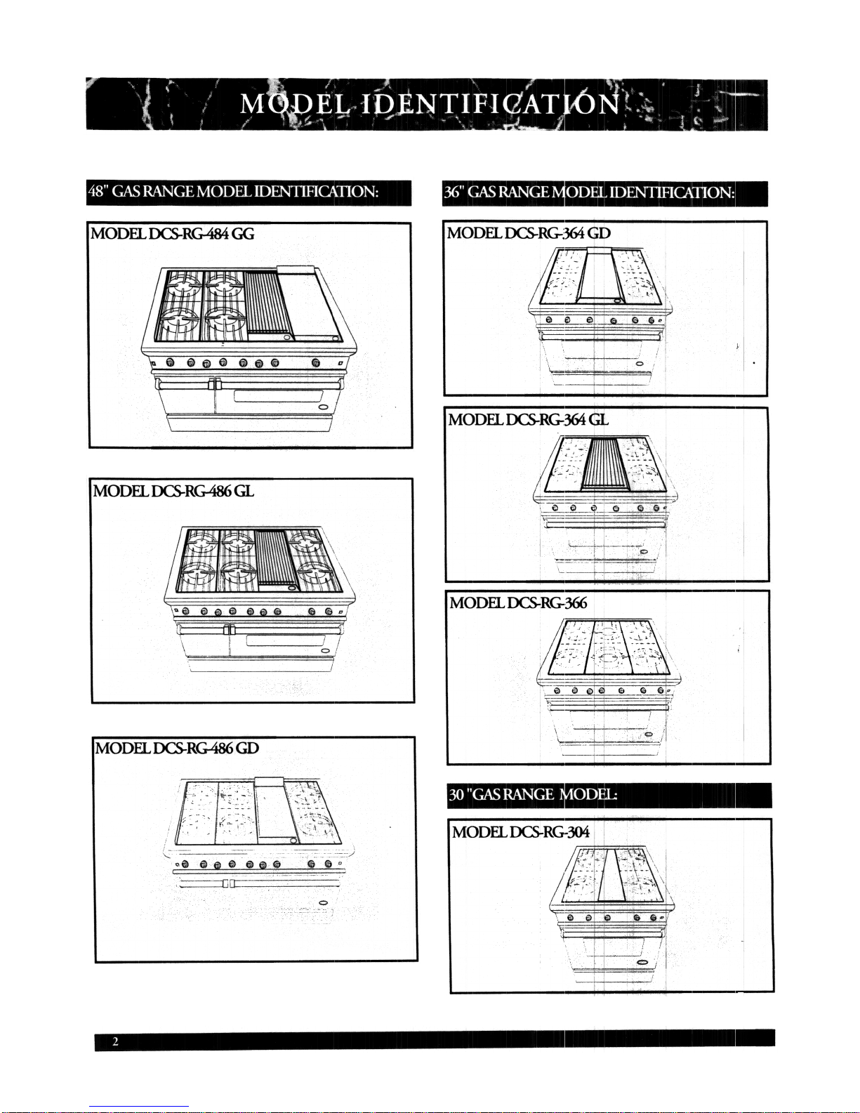
The Dynamic Cooking Systems Professional
Ranges and Cool,tops feature a large number of
features varying vvith each model.Included on the
48", 36", and 30"' ranges is a large capacity gas
oven, with a gas infra red broiler. A smaller ove~
is designed into the 48" Range models also. All
models feature a minimum of 4 open burners,
with the option ,of up to 6 open top burners on
all models except the RG 304. All the 48" and
36" Ranges and <:::ooktops feature the possibility
of various Grill a][ld Griddle combinations. All
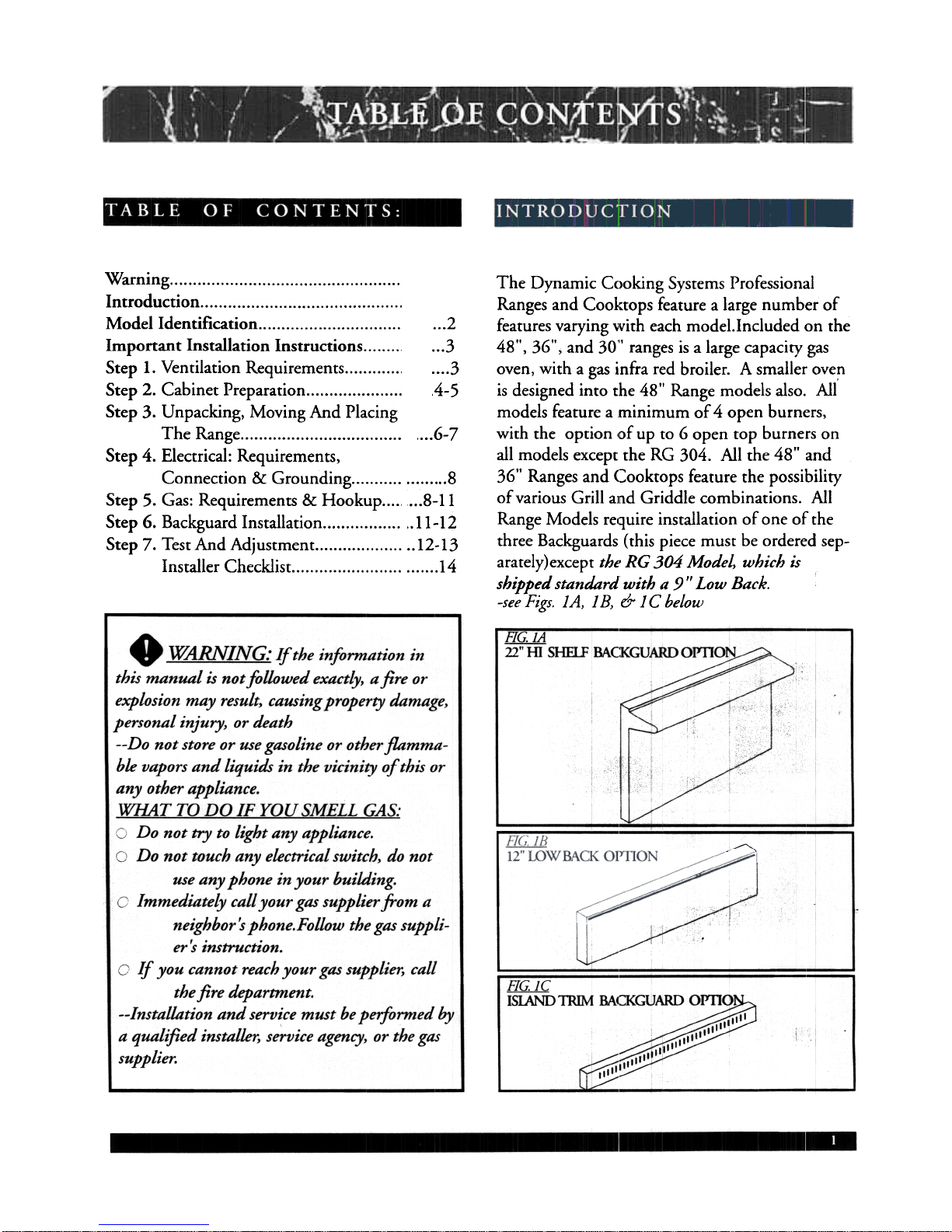
Range Models require installation of one of the
three Backguards (this piece must be ordered sep-
arately}except tht, RG 304 Model, which is
shipped standard with a 9 II Low Back.
-see Figs. lA, 1 B, & 1 C below
...2...3
3
.4-5
,...6-7
Warning Introduction Model Identification Important Installation Instructions Step 1. Ventilation Requirements Step 2. Cabinet Preparation Step 3. Unpacking, Moving And Placing
The Range Step 4. Electrical: Requirements,
Connection & Grounding Step 5. Gas: Requirements & Hookup Step 6. Backguard Installation Step 7. Test And Adjustment Installer Checklist
,
...8-,.11-
..12-
.J..
..811
12
13
14
Tested in accordance with ANSI Z21.
Standard for Household Cooking Gas
Appliances.
-1990 A suitable exhaust hood must be installed above
the range / cooktclp. The following chart indicates the minimum blower capacity recommend.
ed for hood ventilation.
These ranges and must be installed in conjunc-
tion with a suitable overhead vent hood. (See Step
1 for ventilation requirements.) Due to the professional high heat capacity of this unit, particular
attention should be paid to the hood and duct
work installation to assure it meets local building
codes. To eliminate risk of burns or fire by reach-
ing overheated surface units, cabinet storage
located above the surface units should be avoided.
.{:;f1U ~[;: Ventilation hoods and blowers
are designed for USt' with single wall ducting.
Howeve1; some 10ctOrl building codes or inspectors
may require doubu' wall ducting. Consult local
building codes and/or local agencies, before starting,
to assure that hood and duct installation will meet
local. requirements.
Hood blower speeds should be variable to reduce
noise and loss of heated or air conditioned household air when ma>:imum ventilation is not
required. Normally, the maximum blower speed
is only required when using the B-B-Q grill.
For best smoke elimination, the lower edge 06 the
hood should be installed a minimum of 30" to a
maximum of 36" above the range cooking sur-
face, -See Fig. 3. If the hood contains any combustible materials (i.e. a wood covering) it must
be a minimum of ;36" above the cooking surface.
Check local building codes for the proper
method of range installation. Local codes vary.
Installation, Electrical connections, and
Grounding must comply with all applicable
codes. In the absence of local codes, the range I
cooktop should be installed in accordance with
the National Fuel Gas Code ANSI Z223.11988 and National Electrical Code ANSI I NFPA
70-1990.
Be sure that the unit being installed is set up for
the kind of gas being used. The gas range is
shipped from the factory set and adjusted for
Natural Gas. If LP Gas (propane) is to be used,
refer to Step Five for instructions on converting
the range for LP use. (The unit is shipped
equipped for LP conversion: no additional parts
are required, but adjusting is necessary) Only a
qualified service technician or installer should
make this conversion.
Due to a high volt;Lme of vent.~lation air, a source
of outside replacenrlent air is recommended. This
is particularly imp'Drtant for tightly sealed and
insulated homes. A reputable .heating and ventilating contractor s]t1ould be consulted.
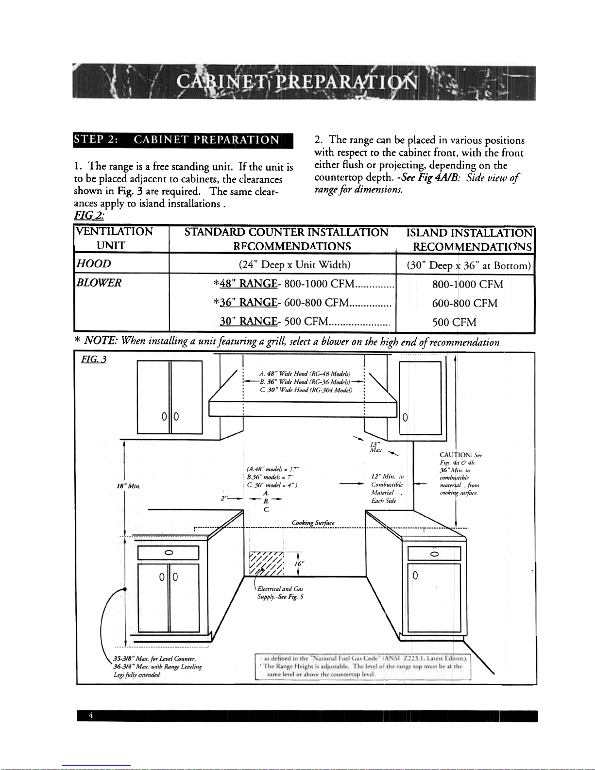
2. The range can be placed in various positions
with respect to the cabinet front, with the front
1. The range is a free standing unit. If the unit is either flush or projecting, depending on the
to be placed adjacent to cabinets, the clearances counrertop depth. -See Fig 4AJB: Side vieul of
shown in Fig. 3 are required. The same clear- range for dimensions.
ances apply to island installations.
FIG 2:
VENTILATION STANDARD COUNTER INSTALLATION ISLAND INSTALLATION
UNIT RECOMMENDATIONS RECOMMENDATIONS
* NOTE: When installing a unit featuring a grill, select a blower on the h~gh end of recommendation
ElG :1
~
-A. 48" Wid" Hood (RG-48 Mod,,/s)
;-B. 36" Wid.. Hood (RG-36 Modr/S;
: C. 30" Wid.. Hood (RG-304 Mod,,!
"'
-
ri.~, 4a &4b
36" Min 10
rombUJlibl..
malrrial ,from
cookin~ ,uifacr
[A.48"moa,ls = '
B.36" motitls = 7'
C. 30" mod,! = 4
A.
~B.-
c.
12" !\crill. t.."'
Comb.stibl..
lI1at"ial
E""h :)id,
I
18" Min.
]',--
~~~.k.;,~~-~~'i~~~
I 0 I
L,-"" ,I'
r'/ /.~/(~,
I'
16
+
",crricai anti (,
;uppiy-&. Fig
35-318" Max. for Lrotl Counttr.
36-3/4" Max. with Rangt Ltvtling
Ltg, ftlfv tXttndtd
 Loading...