

Page 1

902
de-Esser
A Harman International Company
¨
Page 2
WARNING
FOR YOUR PROTECTION, PLEASE READ THE FOLLOWING:
WATER AND MOISTURE: Appliance should not be used near water (e.g. near a bath-
tub, washbowl, kitchen sink, laundry tub, in a wet basement, or near a swimming pool,
etc). Care should be taken so that objects do not fall and liquids are not spilled into
the enclosure through openings.
POWER SOURCES: The appliance should be connected to a power supply only of
the type described in the operating instructions or as marked on the appliance.
GROUNDING OR POLARIZATION: Precautions should be taken so that the grounding or polarization means of an appliance is not defeated.
POWER CORD PROTECTION: Power supply cords should be routed so that they are
not likely to be walked on or pinched by items placed upon or against them, paying
particular attention to cords at plugs, convenience receptacles, and the point where
they exit from the appliance.
SERVICING: To reduce the risk of fire or electric shock, the user should not attempt to
service the appliance beyond that described in the operating instructions. All other
servicing should be referred to qualified service personnel.
FOR UNITS EQUIPPED WITH EXTERNALLY ACCESSIBLE FUSE RECEPTACLE:
Replace fuse with same type and rating only.
SAFETY INSTRUCTIONS
NOTICE FOR CUSTOMERS IF YOUR UNIT IS EQUIPPED WITH A POWER
CORD.
WARNING: THIS APPLIANCE MUST BE EARTHED.
The cores in the mains lead are coloured in accordance with the following code:
GREEN and YELLOW - Earth BLUE - Neutral BROWN - Live
As colours of the cores in the mains lead of this appliance may not correspond
with the coloured markings identifying the terminals in your plug, proceed as follows:
¥ The core which is coloured green and yellow must be connected to the
terminal in the plug marked with the letter E, or with the earth symbol, or
coloured green, or green and yellow.
¥ The core which is coloured blue must be connected to the terminal
marked N or coloured black.
¥ The core which is coloured brown must be connected to the terminal
marked L or coloured red.
This equipment may require the use of a different line cord, attachment plug, or
both, depending on the available power source at installation. If the attachment
plug needs to be changed, refer servicing to qualified service personnel who
should refer to the table below. The green/yellow wire shall be connected
directly to the unit's chassis.
WARNING: If the ground is defeated, certain fault conditions in the unit or in the
system to which it is connected can result in full line voltage between chassis
and earth ground. Severe injury or death can then result if the chassis and
earth ground are touched simultaneously.
U.K. MAINS PLUG WARNING
A moulded mains plug that has been cut off from the cord is unsafe. Discard the
mains plug at a suitable disposal facility. NEVER UNDER ANY CIRCUM-
STANCES SHOULD YOU INSERT A DAMAGED OR CUT MAINS PLUG INTO
A 13 AMP POWER SOCKET. Do not use the mains plug without the fuse cover
in place. Replacement fuse covers can be obtained from your local retailer.
Replacement fuses are 13 amps and MUST be ASTA approved to BS1362.
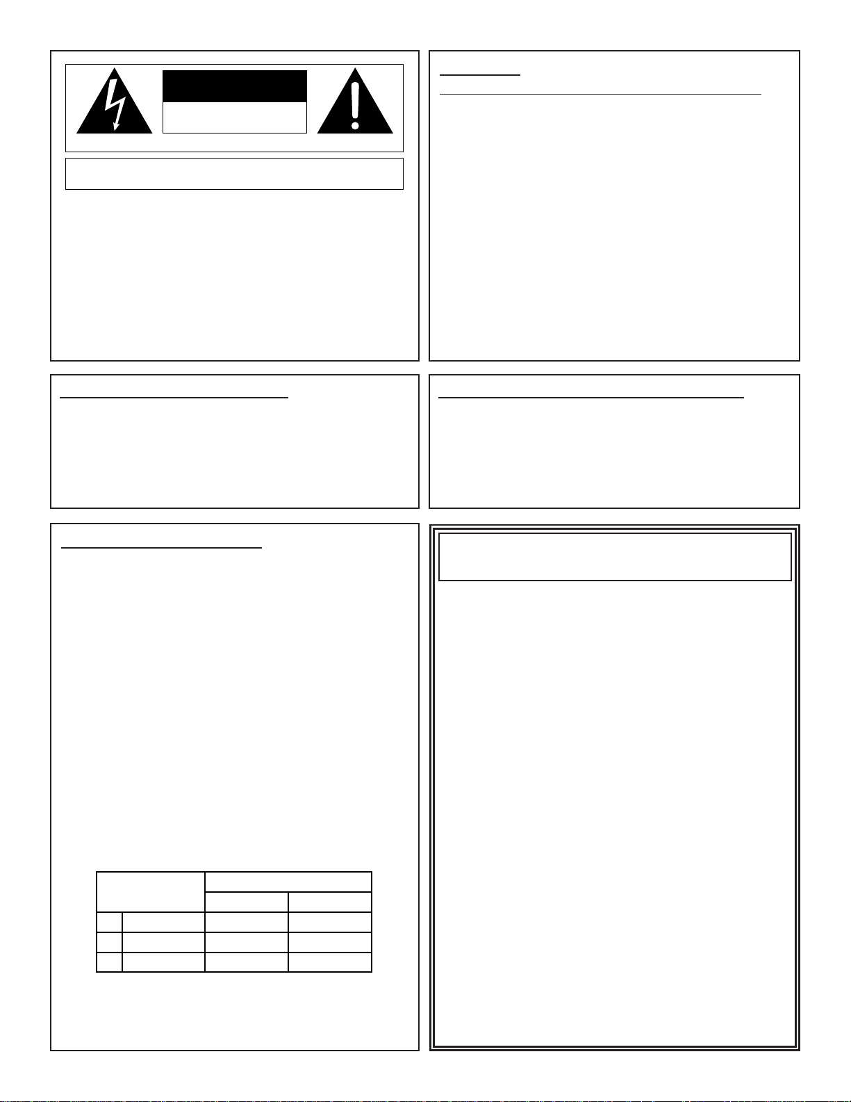
The symbols shown above are internationally accepted symbols that warn of
potential hazards with electrical products. The lightning flash with arrowpoint in
an equilateral triangle means that there are dangerous voltages present within
the unit. The exclamation point in an equilateral triangle indicates that it is necessary for the user to refer to the ownerÕs manual.
These symbols warn that there are no user serviceable parts inside the unit.
Do not open the unit. Do not attempt to service the unit yourself. Refer all servicing to qualified personnel. Opening the chassis for any reason will void the
manufacturerÕs warranty. Do not get the unit wet. If liquid is spilled on the unit,
shut it off immediately and take it to a dealer for service. Disconnect the unit
during storms to prevent damage.
CAUTION
ELECTROMAGNETIC COMPATIBILITY
This unit conforms to the Product Specifications noted on the Declaration of
Conformity. Operation is subject to the following two conditions:
¥ this device may not cause harmful interference, and
¥ this device must accept any interference received, including interference
that may cause undesired operation.
Operation of this unit within significant electromagnetic fields should be avoided.
¥ use only shielded interconnecting cables.
DECLARATION OF CONFORMITY
ManufacturerÕs Name: dbx Professional Products
ManufacturerÕs Address: 8760 S. Sandy Parkway
Sandy, Utah 84070, USA
declares that the product
dbx 902
conforms to the following Product Specifications:
EMC: EN 55013 (1990)
EN 55020 (1991)
Supplementary Information:
The products herewith comply with the requirements of the EMC
Directive 89/336/EEC (1989), as amended by the CE marking directive 93/68/EEC (1993).
dbx Professional Products
President
8760 S. Sandy Parkway
Sandy, Utah 84070, USA
April 30, 1996
European Contact: Your Local dbx Sales and Service Office or
International Sales Office
68 Sheila Lane
Valparaiso, Indiana
46383, USA
Tel: (219) 462-0938
Fax: (219) 462-4596
RISK OF ELECTRIC SHOCK
DO NOT OPEN
ATTENTION: RISQUE DE CHOC ELECTRIQUE - NE PAS OUVRIR
WARNING: TO REDUCE THE RISK OF FIRE OR ELECTRIC
SHOCK DO NOT EXPOSE THIS EQUIPMENT TO RAIN OR MOISTURE
CONDUCTOR
L
N
E
LIVE
NEUTRAL
EARTH GND
WIRE COLOR
Normal Alt
BROWN
BLUE
GREEN/YEL
BLACK
WHITE
GREEN
Page 3

WARRANTY 2
INTRODUCTION 2
F
EATURES 2
INSPECTION 2
CONNECTING THE 902 TO YOUR AUDIO SYSTEM 3
FRONT PANEL OPERATIONS 4
APPLICATIONS 4
SPECIAL APPLICATIONS 4
SPECIFICATIONS 5
902
¨
1
manual contents
Page 4

WARRANTY
1. The warranty registration card that accompanies this product must be mailed within 30 days after purchase date
to validate this warranty. Proof-of-purchase is considered to be the burden of the consumer.
2. dbx warrants this product, when bought and used solely within the U.S., to be free from defects in materials and
workmanship under normal use and service.
3. dbx liability under this warranty is limited to repairing or, at our discretion, replacing defective materials that show
evidence of defect, provided the product is returned to dbx WITH RETURN AUTHORIZATION from the factory,
where all parts and labor will be covered up to a period of two years. A Return Authorization number must be
obtained from dbx by telephone. The company shall not be liable for any consequential damage as a result of the
product's use in any circuit or assembly.
4. dbx reserves the right to make changes in design or make additions to or improvements upon this product without incurring any obligation to install the same additions or improvements on products previously manufactured.
5. The foregoing is in lieu of all other warranties, expressed or implied, and dbx neither assumes nor authorizes any
person to assume on its behalf any obligation or liability in connection with the sale of this product. In no event
shall dbx or its dealers be liable for special or consequential damages or from any delay in the performance of
this warranty due to causes beyond their control.
INTRODUCTION
Congratulations on your purchase of the dbx 902 De-Esser. This manual provides you with the steps needed to
install and operate the 902 module. The manual also includes information on completing the registration card, as
well as customer support telephone numbers.
FEATURES
The dbx model 902 De-Esser is designed for use in the F900A mainframe or the FS900 miniframe. The 902Õs
unique features make it possible to achieve the exact amount of de-essing desired regardless of variations in signal
levels.
Log-Domain Processing: The 902 examines the differences in dB between the high frequency and full-bandwidth
portions of the signal, allowing de-essing of signals which change in level by as much as 60 dB. Conventional
de-essers require readjustment of their threshold control when a vocalist drops from singing voice to a whispering voice. By contrast, the 902 does not even have a threshold control to require adjustment.
User-Defined Crossover Frequency/HF Only or Broadband Operation: The two-pole, maximally flat filter design
used by the 902 in separating high frequencies from low frequencies can be user adjusted over a range of 800
Hz to 8 kHz. This, in conjunction with the HF only mode, enables the 902 to be used for special, non-vocal
applications such as removing ÒclicksÓ from a close-micÕd guitar.
RMS Level Detection: dbx patented RMS level detectors enable the 902 to sense level on the same basis as the
human ear -- providing a natural and accurate response to audio waveforms.
Other features include:
¥ Control Voltage Inputs and Outputs
¥ Expanded Scale LED Metering
¥ Hard-Wired Bypass Switch
I
NSPECTION
Your dbx 902 was carefully manufactured, inspected and tested at the factory. If obvious physical damage is noticed
contact the carrier immediately to make a damage claim.
If the 902 appears to malfunction during use, refer to the connections section of this manual to ensure proper connections, then contact your dealer or our factory service personnel for advice on how to proceed.
902
¨
2
Page 5

We suggest saving the shipping carton and packaging materials for safely transporting your 902 in the future.
Packed in the carton you should find the following:
¥ 902 unit
¥ operations manual (this is it)
¥ warranty registration card
Take the time now to fill out your warranty registration card and send it to us.
CONNECTING THE 902 TO YOUR AUDIO SYSTEM
Terminating resistors are not necessary for the 902Õs audio input to provide proper operation, but they may be
required if the input is fed from a device designed for a specified load impedance, such as a passive equalizer. The
902 has an actual input impedance of 20 k½ in balanced mode and >10 k½ if unbalanced. This makes the 902
audio input suitable for use with virtually any source impedance, low or high.
B
ALANCED
If you are using the F900A mainframe, connect the signal leads to the A+ and A- terminals; if you are using an
FS900 miniframe, connect the hot (+) signal lead to pin 3 of the XLR connector, and the cold (-) signal lead to pin 2
of the XLR connector. For custom installations refer to the 902 diagram in Figure 1. If hum develops, try attaching
the shield to the ground connection at the 902 input.
UNBALANCED
If you are using an F900A mainframe, wire the hot lead to the A+ terminal, and the shield to the A- terminal; if you
are using an FS900 miniframe, wire the hot lead to pin 3 of the XLR connector, and wire the shield to pin 2 of the
XLR connector. For custom installations refer to the 902 circuit board diagram in figure 1. If hum develops, try connecting a jumper between the A- terminal and the 902Õs input ground. Reversing the wires to the input terminals will
result in the output signal from the 902 being 180 degrees out of phase with the input signal.
Figure 1: 902 Audio
Connections
For maximum hum rejection avoid common grounding at the 902Õs input and output. The best starting point is to
ground the shield of the input cable at the source device, leaving it unconnected to the 902, and to ground the
shield of the output cable to the ground terminal of the 902, leaving it unconnected at the receiving device.
CONNECTING THE AUDIO OUTPUTS
The output of the 902 is designed to feed balanced or unbalanced loads of 600 ½ or greater. The output stage is
single-ended; in normal operation the B- terminal is connected internally to the circuit ground. When the bypass
switch is engaged, the signal inputs are directly connected to the signal output (i.e. A+ to B+, and A- to B-) and the
internal jumper between B- and the circuit ground is removed.
The IN/OUT switch on the 902 introduces no noise into the signal path when it is switched. Switching back and forth
between processed and unprocessed signal may reveal a level difference, depending upon the degree to which the
program material is being de-essed. If a pop or click is apparent when the IN/OUT switch is activated, there is probably a grounding problem in the signal processing system. Compare the grounding of the signal shields to and from
902
¨
3
R74
Audio Balanced Inputs
Audio Unbalanced Output
(Balanced Bypass)
F900A Mainframe
Connections
FS900 Miniframe Rear Panel
2
Control
Voltage
A
Ground
B
C
Out
D
In
ABCD
1 -24V
2 +24V
3 Front Panel Ground
4 Circuit Ground
5 +15V
6 -15V
7 N/C
8 N/C
9 CV IN
10 CV OUT
11 Circuit Ground
12 A+
Bal Audio
}
Input
13 A14 B+
Bal Audio
}
Output
15 B-
dbx 902 Circuit Board
FEMALE
+3A, C
+3B, D
MALE
1
15
902
1-2
-21
Page 6

the 902 with the grounding methods described in the previous sections. If the problem persists, try connecting a
jumper wire between B- and ground. This should cure the popping sound, but the signal will now be unbalanced in
the OUT, or BYPASS mode and hum may increase.
CONNECTIONS FOR SPECIAL APPLICATIONS
Skip this step if you do not intend to use any of the 902 special applications listed below. Refer to the listed page for
information and installation steps for each application.
FRONT PANEL OPERATIONS
Figure 2: 902 Front Panel
GAIN REDUCTION LEDS: Indicate the amount of de-essing in dB.
IN/OUT SWITCH: Allows the user to hardwire bypass the 902 for before/after comparisons.
Controls and indicators continue to function in the bypass mode. For de-essing it
should be left in the normal mode.
MODE S WITCH: Allows the 902 de-essing action to affect either the entire audio band-
width, or the high frequencies only. For de-essing it should be left in the normal
mode. For Òde-edgingÓ and Òde-clickingÓ of some instrumental material it should
be put in the HF ONLY mode.
FREQUENCY CONTROL: Selects the frequency at which the 902 splits the audio signal
into high and low frequency portions for evaluation. The 902 detects sibilant
material by comparing (in dB) the high frequency level of an audio signal and the
full bandwidth level of the signal. When the high frequency level is excessive relative to the full bandwidth level, the 902 will de-ess. For normal vocal de-essing,
this control should be set around the 12:00 position (2.5 kHz) position. For special processing of instrumental material, the control should be swept back and
forth until the optimum setting is obtained.
RANGE CONTROL: Sets the amount of de-essing effect produced when a sibilant is detect-
ed. For normal vocal de-essing, leave this control in the NORMAL region.
Turning the RANGE control clockwise beyond the NORMAL region will cause
vocal sibilants to be excessively attenuated or Òswallowed.Ó More extreme settings are useful for special effects and for processing instrumental material.
Since the 902 is effectively inaudible in normal Òde-essingÓ operation (sibilants simply sound
normal) there may be a tendency to turn the range control clockwise beyond the normal
region. Prolonged listening will, however, reveal the extra de-essing effect as unnatural for
vocals.
APPLICATIONS
One of the primary design goals for the 902 de-esser is to eliminate the need for any adjustments when de-essing a
wide variety of vocal material. However, several other interesting and worthwhile effects can be obtained with the
user controls provided. By adjusting the filter cutoff frequency and the maximum amount of gain reduction, the high
end of certain percussive source material can be altered on a dynamic basis. For example, the pick noise on a guitar track can be completely eliminated without affecting the timbre of the guitar. When a guitar string is struck, the
first sound produced is a high level, high frequency ÒclickÓ, with the amplitude of the fundamental string vibration
building up relatively slowly. By processing a guitar track through the de-esser, the track can be brightened considerably via normal high-frequency boost equalization without exaggerating annoying pick noises.
SPECIAL APPLICATIONS
USING THE EXTERNAL CONTROL VOLTAGE INPUT (D-)
The CV input and output connections come from the factory jumpered together for normal de-esser operation. To
use the CV input, this jumper (R74) must be removed. Jumper R74 is shown in figure 1 on page 3. Figure 3 on
page 5 illustrates a way of setting up the external wiring to the 902 using normalling type connectors so the CV
input can be accessed when necessary.
902
¨
4
1
G
A
2
I
N
3
R
4
E
6
D
U
8
C
T
10
I
O
12
N
15
d
B
20
1.8K 4K
800Hz 8KHz
FREQUENCY
NORM
ONLY
2.5K
IN
MODE
HF
10
0dB 20dB
RANGE
ESSERDE-
Page 7

The CV input provides direct access to the control port of the dbx VCAof the 902 for gain control. This provides the
user with the ability to use the 902 as an automatable level control. The dbx VCA provides linear-gain tracking in
decibels over a range of -100 to +40 dB with 1% accuracy. An output of 0 V produces 0 dB of gain through the
VCA. The control port should be driven by an op-amp or other low-impedance source. A bypass capacitor may be
required between the CV input and ground to prevent the audio signal from bleeding into this control port and causing modulation distortion.
USING THE CONTROL VOLTAGE OUTPUT
The control voltage output is a DC voltage which changes in proportion to the amount of gain change being produced by the 902. The relationship between this voltage and the amount of gain change is expressed as
CV=50mV/dB gain change. The CV output is low impedance and capable of driving bridged loads of more than 10
k½ and less than .01µf without affecting the operation of the 902.
Figure 3: Control Voltage
Connections
SPECIFICATIONS
Input Impedance: 20 k½ balanced, >10 k½ unbalanced
Output Impedance: 22 k½, into 600 ½ or greater
Maximum Input Level: +24 dBu
Maximum Output Level: +24 dBu into 600 ½ or greater
Frequency Response: 20 Hz - 20 kHz (+0/-3dB)
Dynamic Range: 115 dB
Distortion: Typically .008 % at 1 kHz
Equivalent Input Noise: -90 dBu, 20 Hz - 20 kHz Bandwidth, unweighted
Attack Rate: Program-dependent, 2 ms for 10 dB above threshold, 600µs for 20 dB above threshold, to achieve
63% gain reduction
Release Rate: 925 dB/sec
De-Essing Range: Operates uniformly over input range of -40 dBu to +24dBu without requiring adjustment
Maximum ÒEssÓ Attenuation: Variable 0 to 20 dB
De-Ess Crossover Point: Variable 800 Hz to 8 kHz
Filter Type: 12 dB/ocatve, phase coherent
Gain: Unity
Controls: Frequency, Range
Switches: IN/OUT, Mode (HF ONLY/NORMAL)
Indicators: IN/OUT, HF ONLY
Metering: LED Column: 1, 2, 3, 4, 6, 8, 10, 12, 15, 20 dB gain reduction
Power Supply Requirements: ±15 V Regulated at 60 mA; ±24 V unregulated at 30 mA
Dimensions: Front Panel: 3U high (54Ó, 13.4 cm) x 12Ó W, (3.8 cm); card depth behind front panel: 92Ó (24.2 cm)
Note: specifications subject to change.
902
¨
5
A
Audio
Input
Audio
Output
B
C
CV
Out
D
CV
In
Page 8

¨
8760 South Sandy Pkwy.
Sandy, Utah 84070
Phone: (801) 568-7660
Fax: (801) 568-7662
IntÕl Phone (219) 462-0938
IntÕl Fax: (219) 462-4596
Questions or comments?
E¥mail us at: customer@dbxpro.com
or visit our World Wide Web home page at:
http://www.dbxpro.com
This manual is
part no: 18-2015-B
4/30/96
A Harman International Company
 Loading...