

Page 1
IG2T
MANUALE D’USO – Sezione 1
USER MANUAL - Section 1
BEDIENUNGSANLEITUNG - Abschnitt 1
CARACTERISTIQUES TECHNIQUES - Section 1
MANUAL DEL USUARIO - Sección 1
Le avvertenze nel presente manuale devono essere osservate congiuntamente al “MANUALE D’USO - Sezione2”.
The warnings in this manual must be observed together with the "User Manual - Section 2".
Die Warnungen in diesem Handbuch müssen in Verbindung mit der "BEDIENUNGSANLEITUNG - Abschnitt 2" beobachtet werden”.
Les avertissements speciés dans ce manuel doivent être respectés ainsi que les "CARACTERISTIQUES TECHNIQUES -Section 2".
Las advertencias del presente manual se deben tener en cuenta conjuntamente con las del “Manual del usuario” - Sección 2”.
Page 2

EMI CLASSIFICATION
According to the standards EN 55103 this equipment is designed and suitable to operate in E3 (or lower E2, E1)
Electromagnetic environments.
FCC CLASS B STATEMENT ACCORDING TO TITLE 47, CHAPTER I,
SUBCHAPTER A, PART 15, SUBPART B
This device complies with part 15 of the FCC Rules. Operation is subject to the following two conditions: (1) This
device may not cause harmful interference, and (2) this device must accept any interference received, including
interference that may cause undesired operation.
WARNING
Make sure that the loudspeaker is securely installed in a stable position to avoid any injuries or damages to
persons or properties. For safety reasons di not place one loudspeaker on top of another without proper fastening
systems. Before hanging the loudspeaker check all the components for damages, deformations, missing or
damaged parts that may compromise safety during installation. If you use the loudspeakers outdoor avoid spots
exposed to bad weather conditions.
Contact dBTechnologies for accessories to be used with the speakers. dBTechnologies will not accept any
responsibility for damages caused by inappropiate accessories or additional devices.
INGENIA IG2T Cod. 420120238 REV. 1.1
2
Page 3

ITALIANO
ENGLISH
DEUTSCH
FRANÇAIS
ESPAÑOL
INGENIA IG2T Cod. 420120238 REV. 1.1
3
Page 4

Italiano
INDICE
1. INFORMAZIONI GENERALI ................................................................................................... 6
BENVENUTI! ........................................................................................................................ 6
PANORAMICA INTRODUTTIVA .......................................................................................... 6
RIFERIMENTI PER L’UTENTE ................................................................................................ 6
CARATTERISTICHE MECCANICHE ED ACUSTICHE ............................................................. 7
DIMENSIONI ............................................................................................................................................... 7
COPERTURA ACUSTICA ............................................................................................................................. 7
ACCESSORI ................................................................................................................................................. 8
CARATTERISTICHE DELLA SEZIONE DI AMPLIFICAZIONE E DI CONTROLLO ................... 9
SEZIONE DI INPUT E DI CONTROLLO ...................................................................................................... 10
SEZIONE DI ALIMENTAZIONE .................................................................................................................. 11
2. PRIMA ACCENSIONE ............................................................................................................ 12
CONTENUTO DELLA CONFEZIONE .................................................................................. 12
INSTALLAZIONE ................................................................................................................ 12
COLLEGAMENTO DEGLI INGRESSI .......................................................................................................... 12
COLLEGAMENTO DELL’ ALIMENTAZIONE ............................................................................................... 13
COLLEGAMENTO DELLE USCITE FRA PIÙ MODULI (rilancio dell’alimentazione) ................................ 14
COLLEGAMENTO DELLE USCITE FRA PIÙ MODULI (rilancio del segnale audio) ................................. 15
UTILIZZO DI UNA COPPIA DI DUE DIFFUSORI IG2T IN COLONNA ........................................................ 16
3. PANNELLO DI CONTROLLO E MENU DI SETTAGGIO ........................................................ 17
ACCESSO AI MENU ........................................................................................................... 17
IL MENU BUILD SYSTEM................................................................................................... 20
SYSTEM CHECK ........................................................................................................................................ 20
SYSTEM STRUCTURE ................................................................................................................................ 20
SYSTEM TYPE ........................................................................................................................................... 21
IL MENU SAVE/LOAD SYSTEM.......................................................................................... 21
IL MENU ACOUSTIC CORRECTION ................................................................................... 22
IL MENU STAGE ALIGNMENT ........................................................................................... 23
IL MENU SYSTEM DELAY .................................................................................................. 23
IL MENU MICROPHONE SETTING .................................................................................... 24
IL MENU SYSTEM COVERAGE .......................................................................................... 25
IL MENU SUBWOOFER MATCHING ................................................................................. 26
IL MENU OPTIONS ............................................................................................................ 27
PASSWORD .............................................................................................................................................. 27
CONTRAST ................................................................................................................................................ 27
STAND-BY ................................................................................................................................................. 27
RESTORE ................................................................................................................................................... 27
INFO ......................................................................................................................................................... 27
EXIT........................................................................................................................................................... 27
IL MENU EXIT .................................................................................................................... 28
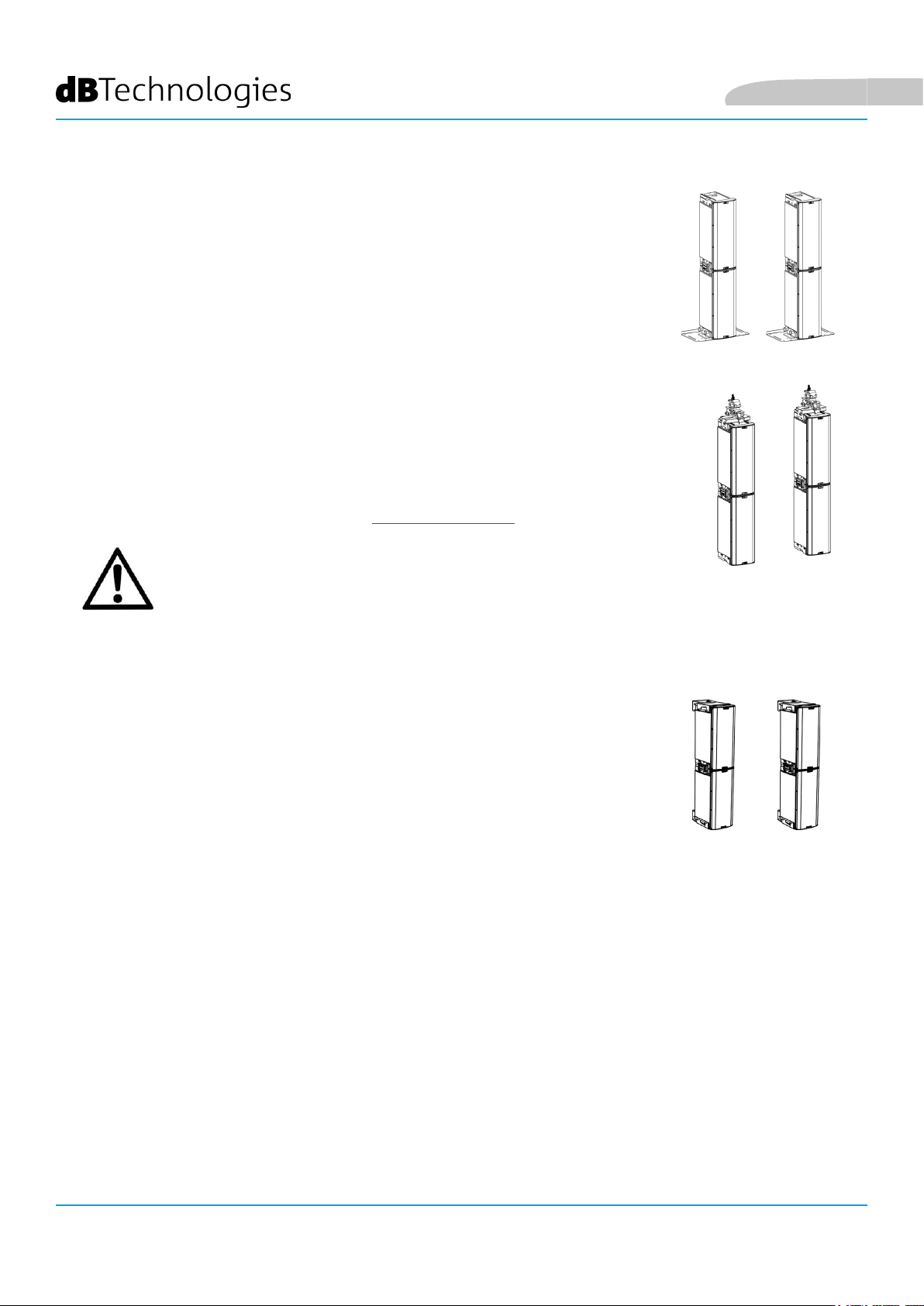
4. ESEMPI DI INSTALLAZIONE ................................................................................................. 29
INSTALLAZIONE SU STATIVO ............................................................................................ 29
INGENIA IG2T Cod. 420120238 REV. 1.1
4
Page 5

Italiano
INDICE
INSTALLAZIONE SU SUBWOOFER .................................................................................... 29
INSTALLAZIONE SU SUBWOOFER CON PALO ................................................................. 29
INSTALLAZIONE A TERRA ................................................................................................. 30
INSTALLAZIONE IN SOSPENSIONE ................................................................................... 30
INSTALLAZIONE A MURO CON STAFFE ........................................................................... 30
IL DIGITAL STEERING ........................................................................................................ 31
5. AGGIORNAMENTO DEL FIRMWARE .................................................................................. 32
6. RISOLUZIONE DEI PROBLEMI ............................................................................................. 33
7. SPECIFICHE TECNICHE ......................................................................................................... 35
GENERALE ................................................................................................................................................ 35
DATI ACUSTICI .......................................................................................................................................... 35
AMPLIFICATORE ....................................................................................................................................... 35
PROCESSORE ............................................................................................................................................ 36
INGRESSI ................................................................................................................................................... 36
DIMENSIONI ............................................................................................................................................. 36
INGENIA IG2T Cod. 420120238 REV. 1.1
5
Page 6

Italiano
1. INFORMAZIONI GENERALI
BENVENUTI!
Grazie per aver acquistato un prodotto progettato e sviluppato in Italia da dBTechnologies! Questo diffusore
attivo a 2 vie a sviluppo verticale racchiude in sé anni di esperienza ed innovazione nel campo della diffusione
sonora, con l’impiego di soluzioni d’avanguardia in campo acustico, elettronico e di ricerca sui materiali.
PANORAMICA INTRODUTTIVA
Il diffusore attivo INGENIA IG2T è un diffusore attivo a 2 vie a sviluppo verticale, equipaggiato con 2
woofer da 8” e 1 driver a compressione con uscita da 1” (voice coil: 1.4”), pilotati da un amplicatore DIGIPRO G3
da 400 W RMS di ultima generazione. Tra le caratteristiche più innovative ci sono:
• un progetto accurato della tromba, con una direttività asimmetrica, specicamente pensata per
garantire ottime prestazioni di copertura acustica, che garantisce una denizione sonora senza
compromessi in diversi contesti di utilizzo indoor e outdoor.
• digital steering controllato dal potente DSP interno, nell’utilizzo di 2 diffusori sovrapposti, che
permette di coniugare la maggiore copertura e potenza sonora con un’accuratezza e una nitidezza
senza compromessi.
• l’immediato riconoscimento automatico della congurazione con 2 diffusori, grazie alla comunicazione
ad infrarossi presente sulle maniglie (tecnologia EPD), alla gestione veloce e personalizzabile gestita
da DSP. In questa congurazione i display OLED si orientano automaticamente. È sufciente agire sulla
sezione di controllo di uno dei due diffusori per pilotare l’intero sistema.
• uno shape innovativo, con l’utilizzo di 2 woofer e 1 driver, in un cabinet che abbina robustezza,
prestazioni sonore, compattezza e maneggevolezza.
• estrema versatilità, che permette di salvare e richiamare le proprie impostazioni in maniera veloce ed
immediata, proteggendo tutti i settaggi con una password impostabile.
RIFERIMENTI PER L’UTENTE
Per utilizzare al meglio il vostro INGENIA IG2T consigliamo di:
• leggere il manuale d’uso quick start presente nella confezione e questo manuale d’uso completo in
ogni sua parte e conservarlo per tutta la durata di vita del prodotto.
• registrare il prodotto sul sito http://www.dbtechnologies.com nella sezione “SUPPORTO”.
• scaricare ed installare il rmware più aggiornato dal sito http://www.dbtechnologies.com nella sezione
“DOWNLOADS” (vedi il capitolo AGGIORNAMENTO DEL FIRMWARE).
• conservare prova d’acquisto e GARANZIA (Manuale d’uso “sezione 2”).
INGENIA IG2T Cod. 420120238 REV. 1.1
6
Page 7
Italiano
CARATTERISTICHE MECCANICHE ED ACUSTICHE
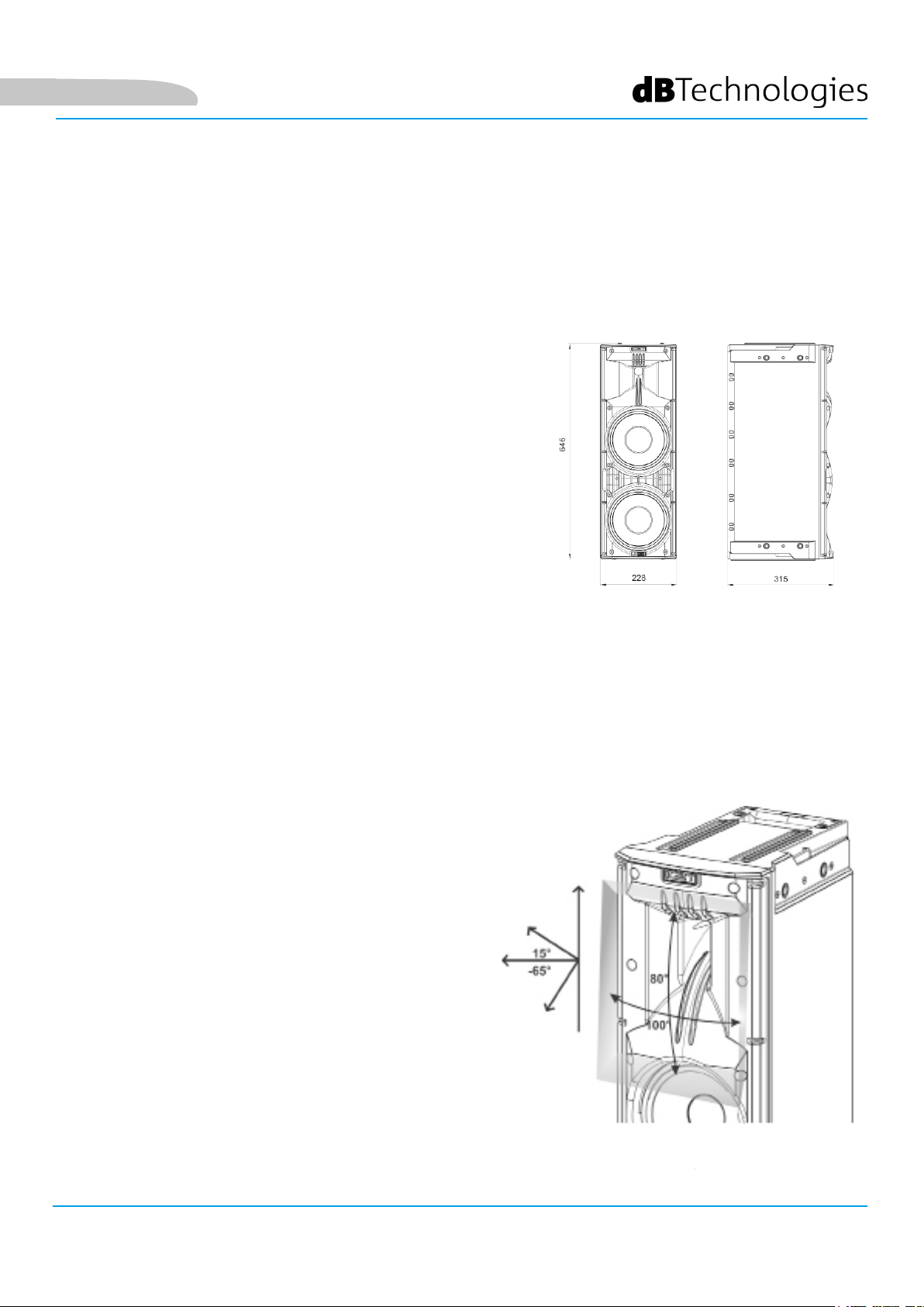
DIMENSIONI
L’INGENIA IG2T integra, in un cabinet di polipropilene rinforzato,
del peso di 12,8 kg, 2 woofer da 8” e un driver a compressione
con uscita da 1” (voice coil: 1.4”) con magneti al neodimio di
eccezionale compattezza, peso e prestazioni. Internamente, una
struttura leggera in metallo, migliora la rigidità meccanica ed il
comportamento acustico. Gli ingombri di un singolo diffusore
sono: 228 x 646 x 315 mm. Le maniglie consentono un facile
trasporto e lo spostamento del diffusore anche da parte di una
sola persona. Sono inne possibili diverse congurazioni, dal
montaggio su subwoofer, all’appendibilità del singolo o doppio
diffusore.
COPERTURA ACUSTICA
La particolare apertura della tromba, schematizzata in gura,
garantisce una direttività totale di 100 x 80° (+15°/- 65°).
Questa copertura verticale asimmetrica garantisce ottime
prestazioni di copertura acustica, in contesti indoor e outdoor.
Utilizzando 2 speaker sovrapposti, inoltre, è possibile
controllare con il digital steering la copertura totale degli
speaker. Questo consente, pur installando 2 IG2T in verticale,
di ottenere l’effetto di un unico speaker inclinato, con tutti i
vantaggi di direttività collegati.
INGENIA IG2T Cod. 420120238 REV. 1.1
7
Page 8
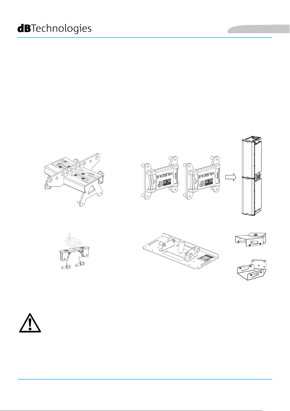
ACCESSORI
Per un rapido montaggio, sono previsti come opzionali i seguenti accessori:
• Fly-bar DRK-IG (ed accessorio TA-IG) per la sospensione verticale.
• Coppia di staffe di bloccaggio LP-IG per il ssaggio di 2 speaker IG2T l’uno sull’altro.
• Stand opzionale GSA-IG per il montaggio su subwoofer (o a terra).
• Staffa a muro WB-IG2 per installazione ssa su parete.
• Una borsa TC-IG2T creata appositamente ed un rain cover RC-M1 sono disponibili per il trasporto e la
protezione del prodotto.
Italiano
Fly Bar DRK-IG Staffe di collegamento LP-IG
TA-IG truss adapter
Stand GSA-IG
ATTENZIONE!
• Non utilizzare mai le maniglie per appendere il diffusore!
Per ogni ulteriore informazione si prega di consultare i manuali relativi.
WB-IG2
INGENIA IG2T Cod. 420120238 REV. 1.1
8
Page 9
Italiano
CARATTERISTICHE DELLA SEZIONE DI AMPLIFICAZIONE E DI CONTROLLO
L’amplicatore digitale di ultima generazione DIGIPRO G3, in
classe D, è il cuore di IG2T ed è capace di una potenza sonora
di 400 W RMS. Grazie a una sezione di alimentazione switching
con funzione di auto-range particolarmente efciente, il sistema
è silenzioso, non necessitando di un raffreddamento ventilato.
Il controllo del sistema è afdato a un potente DSP dedicato
che permette di settare diversi parametri, oltre a gestire
automaticamente la comunicazione fra moduli, in caso di
congurazione a 2 diffusori sovrapposti. In quest’ultimo caso, il
DSP controlla singolarmente i componenti acustici, per ottenere
un fuoco acustico direttivo congurabile (digital steering).
ATTENZIONE!
• Proteggere il modulo dall’umidità.
• Non tentare in nessun modo di aprire
l’amplicatore.
• In caso di malfunzionamento, interrompere
immediatamente l’alimentazione, scollegando
il modulo dalla rete, e contattare un riparatore
autorizzato.
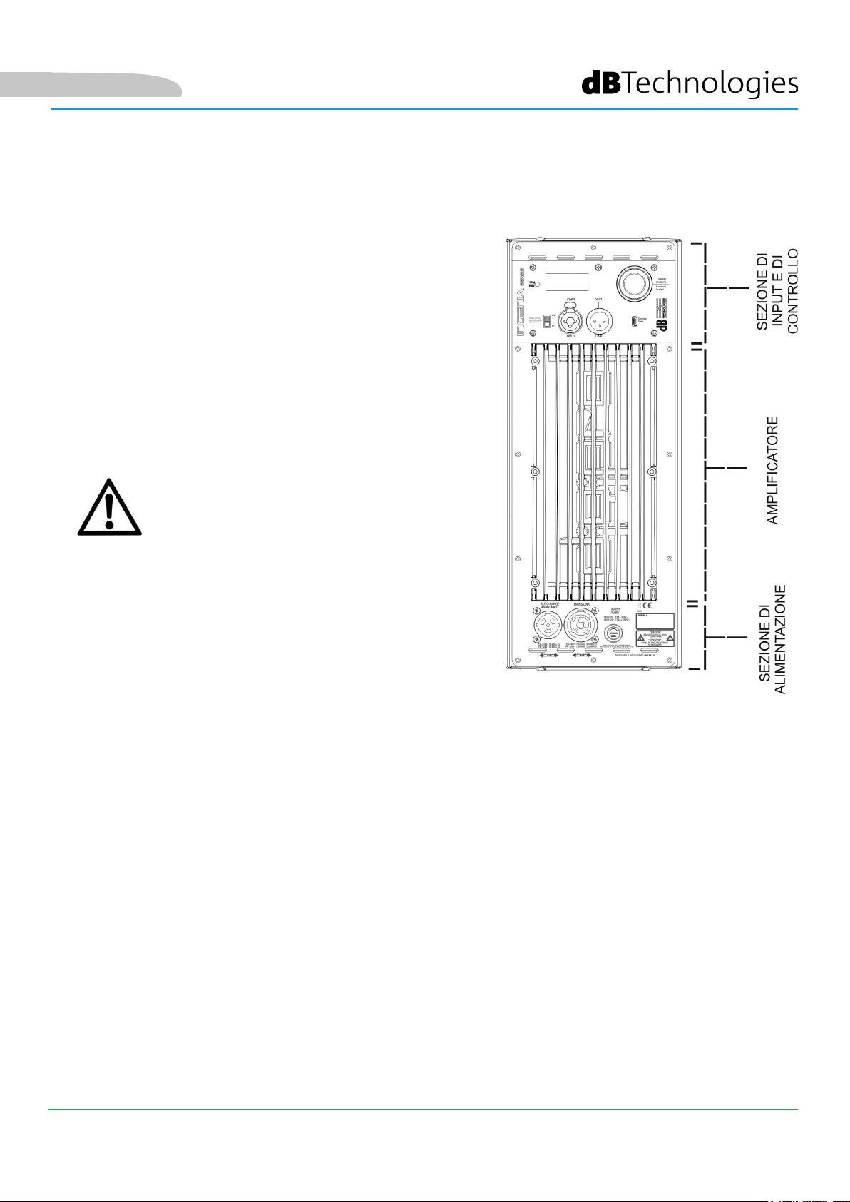
Il pannello del DIGIPRO G3 è caratterizzato da:
• Sezione di Input e Controllo
• Amplicatore
• Sezione di Alimentazione
INGENIA IG2T Cod. 420120238 REV. 1.1
9
Page 10
Italiano
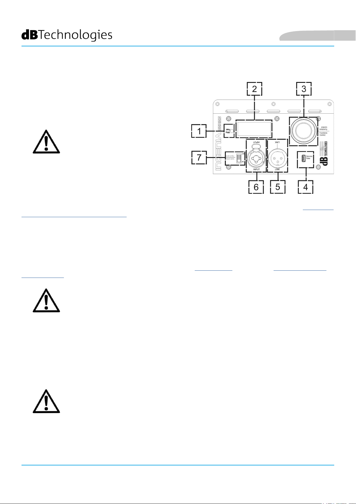
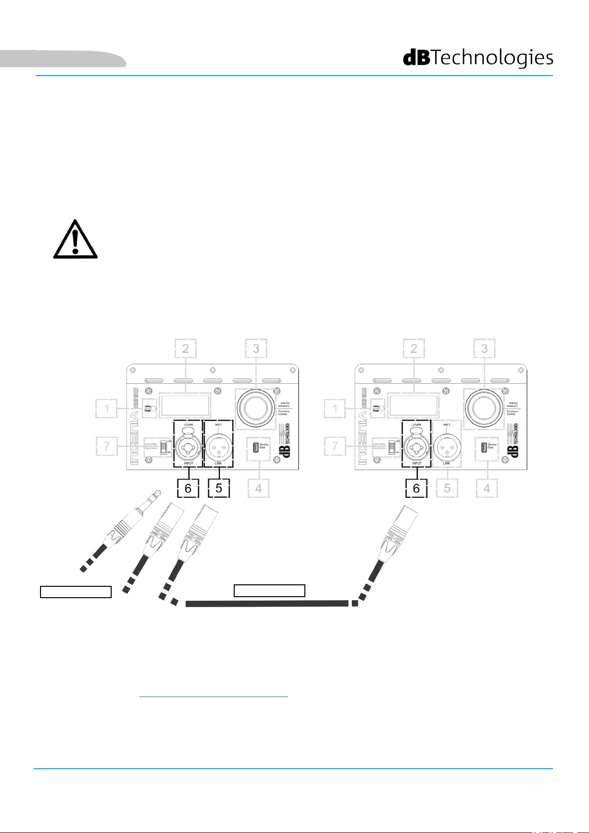
SEZIONE DI INPUT E DI CONTROLLO
1. LED DI “PEAK”
Led rosso che si accende brevemente alla connessione
dell’alimentazione o in caso di funzionamento del limiter
audio.
ATTENZIONE!
Non utilizzare il diffusore per un lungo
periodo con il led acceso o lampeggiante,
che indica un funzionamento di stress
eccessivo in condizioni di distorsione.
2. DISPLAY OLED
Il display si orienta automaticamente in base alla posizione
del diffusore.
È congurabile una funzione di regolazione di contrasto e di autospegnimento (confrontare il capitolo PANNELLO
DI CONTROLLO E MENU DI SETTAGGIO).
3. PUSH ROTARY ENCODER
Il push rotary encoder permette una selezione sia rotativa (selezione di menu e valori), che a pressione
(conferma della selezione effettuata) per navigare nei menu.
4. USB SERVICE DATA
Tramite la porta mini-USB di tipo B è possibile aggiornare, il rmware del prodotto. Per ulteriori informazioni
consultare il sito http://www.dbtechnologies.com alla sezione “DOWNLOADS” ed il capitolo AGGIORNAMENTO
DEL FIRMWARE.
ATTENZIONE!
La connessione USB SERVICE DATA deve essere utilizzata
esclusivamente per aggiornamento rmware del prodotto, non
connettere nessun dispositivo USB all’apparecchio, per evitare
danneggiamenti o malfunzionamenti.
5. USCITA “LINK”
Uscita XLR bilanciata che permette di inviare il segnale audio ad un altro diffusore
amplicato.
6. INGRESSO “INPUT” COMBO
Ingresso XLR-TR-TRS combinato del segnale audio. Permette di utilizzare un connettore XLR bilanciato,
o un ingresso jack-TS o TRS da ¼”.
ATTENZIONE!
Utilizzare solo cavi con connettori originali Neutrik® di alta qualità.
L’utilizzo con connettori differenti o di scarsa qualità potrebbe
compromettere la funzionalità del diffusore.
7. SELETTORE “INPUT SENSITIVITY”
Selettore di ingresso di un segnale proveniente da mixer o linea (“LINE”) o l’ingresso di un segnale che provenga
da un microfono (“MIC”).
INGENIA IG2T Cod. 420120238 REV. 1.1
10
Page 11
Italiano
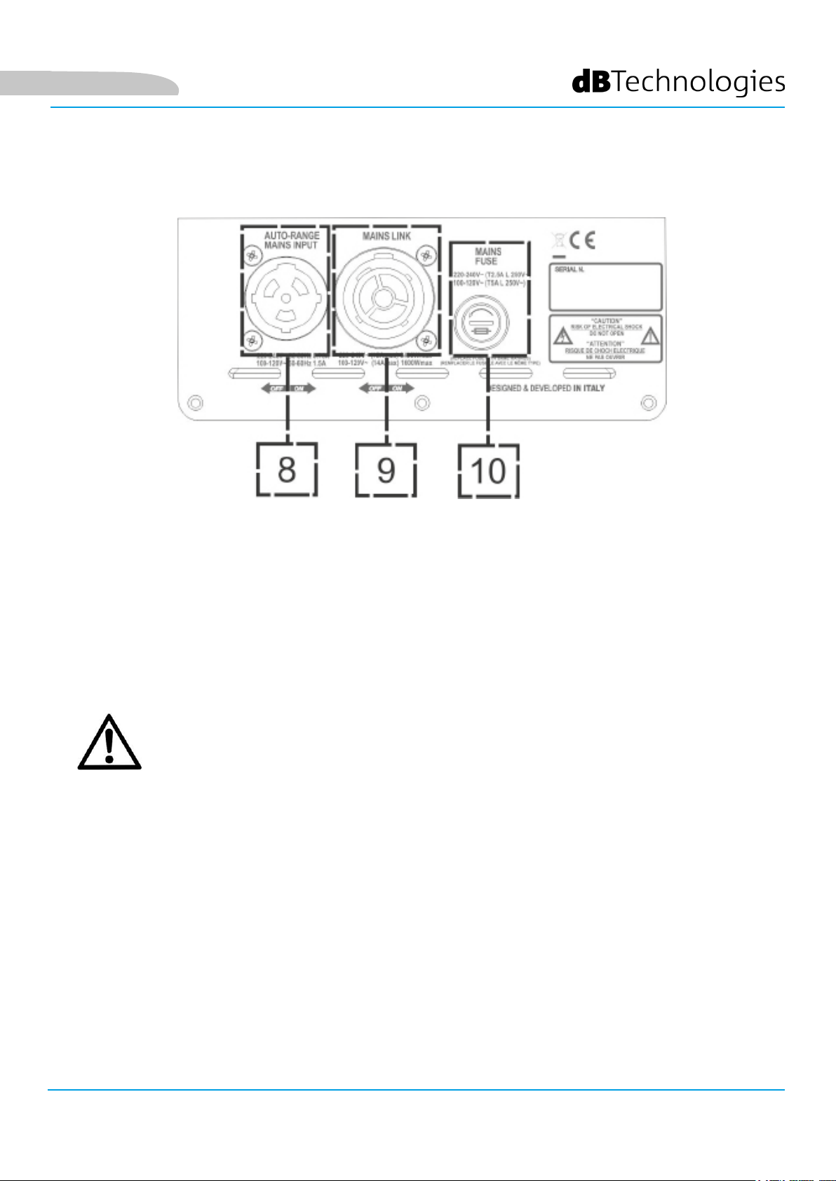
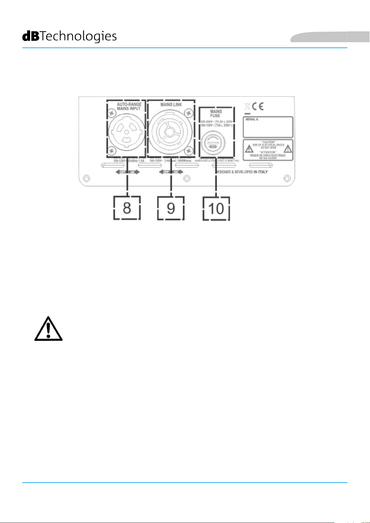
SEZIONE DI ALIMENTAZIONE
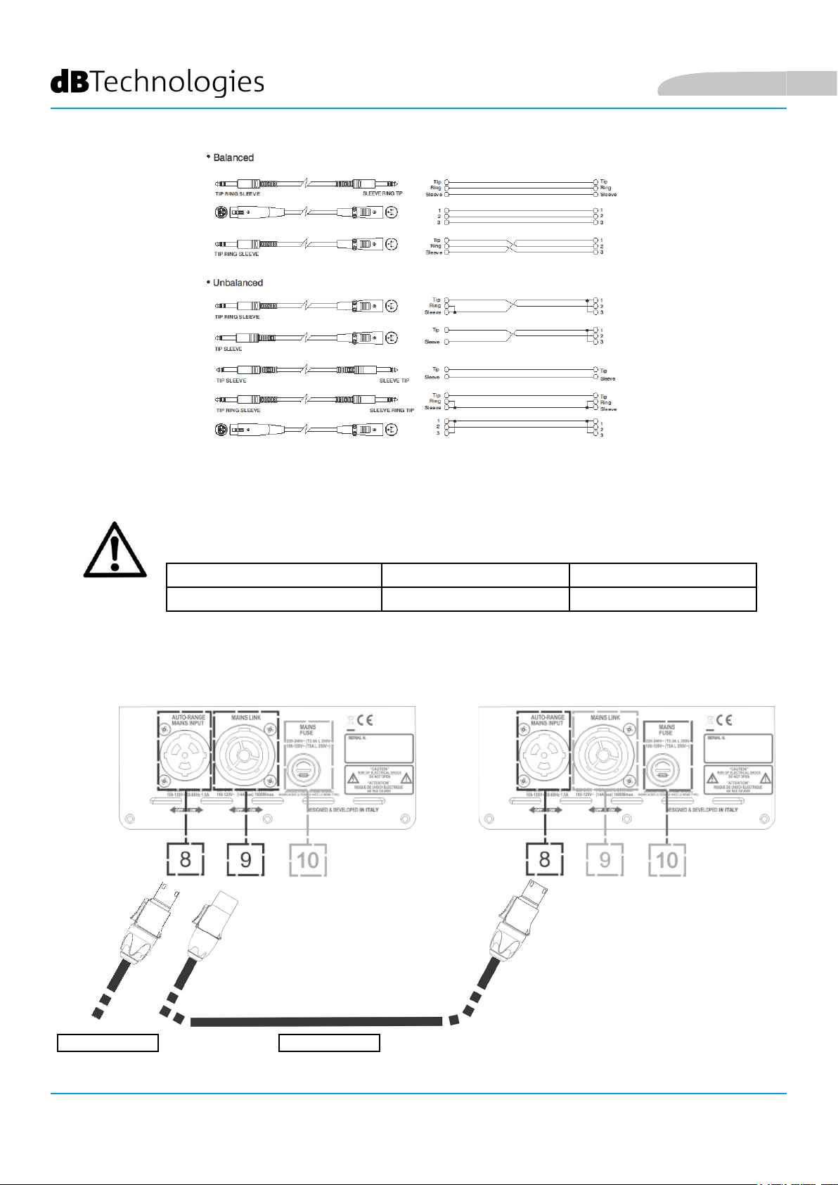
8. INGRESSO DI ALIMENTAZIONE “AUTO-RANGE MAINS INPUT”
Ingresso per connettore Neutrik® powerCON TRUE1.
9. USCITA DI RILANCIO DELL’ALIMENTAZIONE “MAINS LINK”
Grazie alla connessione garantita dal Neutrik® NAC3PX, è possibile
rilanciare l’alimentazione ad un secondo modulo.
10. FUSIBILE DI PROTEZIONE “MAINS FUSE”
Fusibile di rete.
ATTENZIONE!
Il diffusore viene fornito con un fusibile già montato per operare nel range
220-240 V. Se è necessario operare nel range di tensione 100-120 V:
1. Disconnettere ogni connessione, compresa l’alimentazione.
2. Attendere 5 minuti.
3. Sostituire il fusibile con quello fornito nella confezione per il range 100-120 V.
4. Utilizzare solo il cavo di alimentazione in dotazione.
INGENIA IG2T Cod. 420120238 REV. 1.1
11
Page 12
2. PRIMA ACCENSIONE
CONTENUTO DELLA CONFEZIONE
Vericate che il contenuto dell’imballo del diffusore INGENIA IG2T sia completo.
L’imballo contiene:
• cavo di alimentazione con connettore Neutrik® powerCON TRUE1®
• INGENIA IG2T
• quick start e documentazione relativa alla garanzia
• fusibile per il funzionamento nel range di tensione 100-120V
ATTENZIONE!
Il diffusore viene fornito con un fusibile già montato per operare nel range
220-240 V. Se è necessario operare nel range di tensione 100-120 V:
1. Disconnettere ogni connessione, compresa l’alimentazione.
2. Attendere 5 minuti.
3. Sostituire il fusibile con quello fornito nella confezione per il range 100-120 V.
4. Utilizzare solo il cavo di alimentazione in dotazione.
Italiano
INSTALLAZIONE
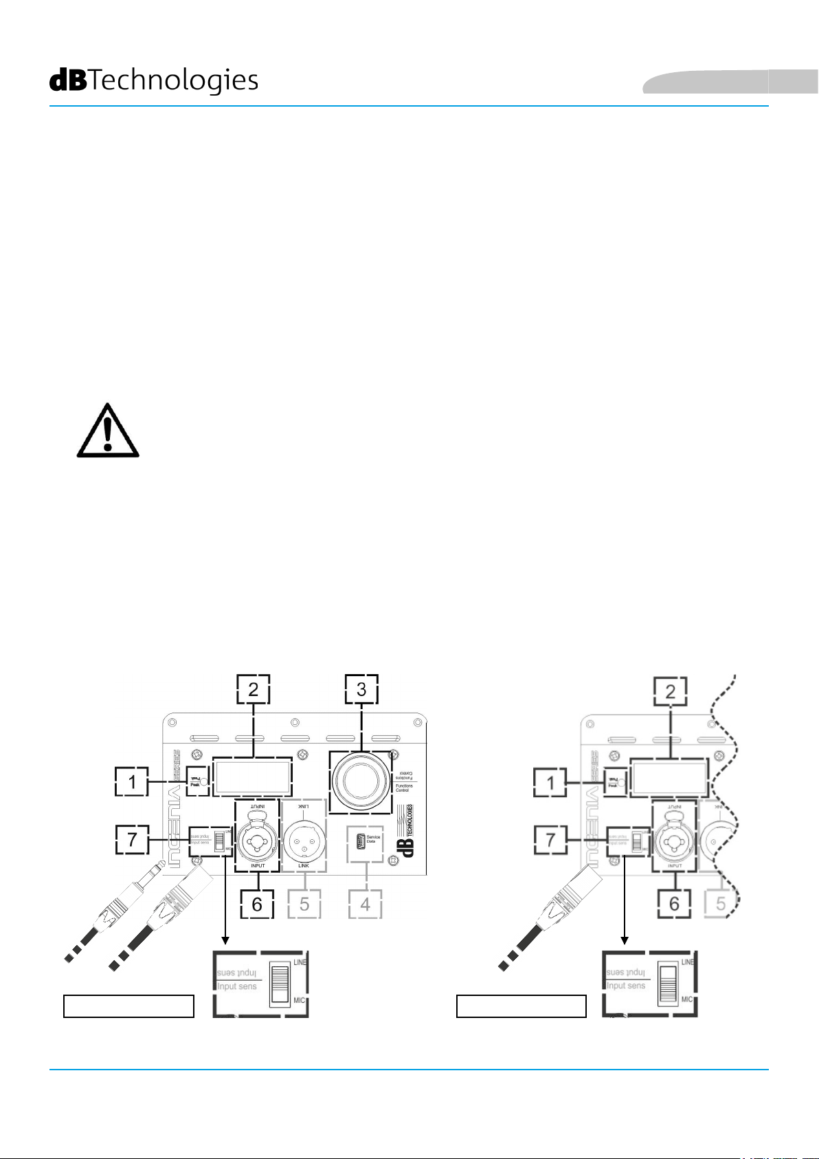
COLLEGAMENTO DEGLI INGRESSI
MIXER / LINEA MICROFONO
INGENIA IG2T Cod. 420120238 REV. 1.1
12
Page 13
Italiano
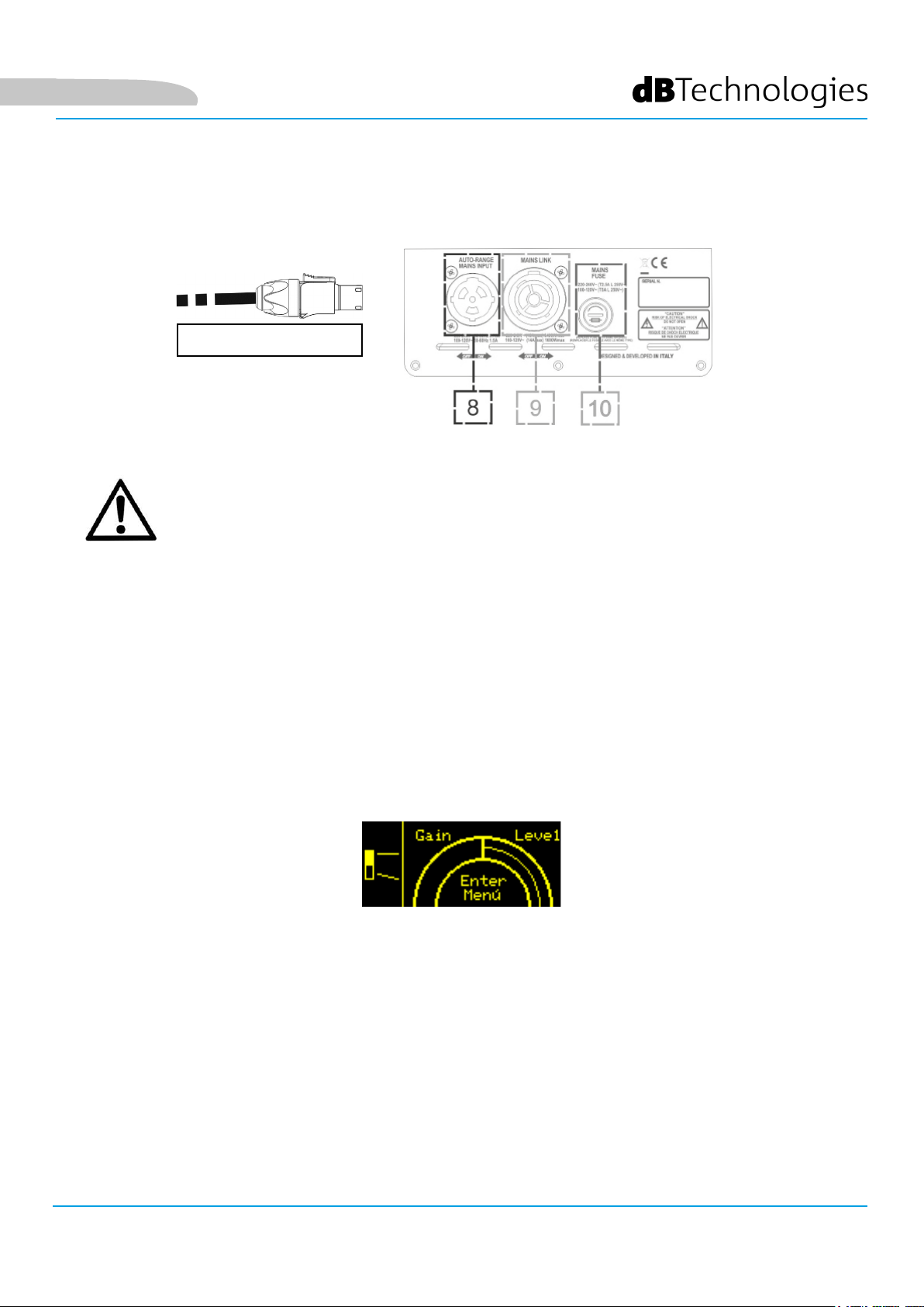
COLLEGAMENTO DELL’ ALIMENTAZIONE
ALIMENTAZIONE
ATTENZIONE!
Utilizzare solo cavi con connettori Neutrik®.
Sostituire i cavi eventualmente danneggiati, per evitare malfunzionamenti
ed una scarsa qualità del suono.
• Collegare l’ingresso audio (6) correttamente, selezionando la sorgente attraverso il selettore “INPUT
SENSITIVITY” (7). In caso di ingresso di segnale proveniente da ingresso di linea o da un’uscita mixer
impostare il selettore (7) su “LINE”. In caso di ingresso microfonico, impostare il selettore (7) su “MIC”.
Per una veloce panoramica sui cavi audio confrontare la tabella a pagina 14.
• Collegare l’alimentazione connettendo il cavo con connettore di tipo Neutrik® powerCON TRUE1® a
“MAINS INPUT” (8)
• All’accensione il led di picco lampeggia brevemente e lo schermo OLED (2) si attiva attestandosi sulla
schermata iniziale:
• Ruotare il PUSH ROTARY ENCODER (3) a sinistra o destra per regolare il volume del sistema al livello
adeguato.
• Vericare la corretta emissione sonora di IG2T
INGENIA IG2T Cod. 420120238 REV. 1.1
13
Page 14
Italiano
COLLEGAMENTO DELLE USCITE FRA PIÙ MODULI (rilancio dell’alimentazione)
NOTA PER L’INSTALLATORE (100-120 V). I dati di targa riportati sul pannello del diffusore sono
riferiti (e limitati) al cavo fornito in dotazione. Nel caso in cui non si utilizzi tale cavo, i limiti
massimi delle correnti (e delle potenze) di LINK ammessi sono indicati nella seguente tabella:
Modello Corrente (100-120 V) Potenza (100-120 V)
IG2T (100-120 V) 18 A 1900 W
I cavi devono essere opportunamente dimensionati e la progettazione, installazione e verica
dell’impianto devono essere effettuate esclusivamente da personale qualicato. A.E.B. Industriale
declina ogni responsabilità in caso di utilizzo di cavi non idonei, non certicati e non compatibili
col corretto dimensionamento dell’impianto e le normative in vigore per il Paese di utilizzo.
ALIMENTAZIONE RILANCIO
INGENIA IG2T Cod. 420120238 REV. 1.1
14
Page 15
Italiano
Grazie all’utilizzo dei connettori Neutrik® PowerCon TRUE1® su IG2T, è possibile rilanciare l’alimentazione dal
primo diffusore ad uno successivo, no ad una corrente massima di 15 A (3400 W) nei paesi con tensione di
alimentazione 220-240Vac e di 14 A (1600 W) nei paesi con tensione di alimentazione 100-120Vac. Per effettuare
questo tipo di connessione è sufciente collegare il cavo di alimentazione fornito a corredo sull’ingresso MAINS
INPUT (8) della prima IG2T e connettere il cavo LINK POWERCON TRUE1® (opzionale) tra l’uscita MAIN LINK
(9) e l’ingresso MAINS INPUT (8) della IG2T successiva. E’ possibile ripetere questo tipo di collegamento no al
raggiungimento della massima corrente ammessa e indicata dal connettore MAINS LINK (9) del primo diffusore.
ATTENZIONE!
Il valore della corrente massima ammessa indicata nei dati di targa della IG2T (MAIN LINK) è
calcolata dalla specica della corrente massima del connettore PowerCON TRUE1
è assoluto ma è in funzione del tipo di cavo utilizzato per la connessione alla rete di alimentazione
della prima IG2T (sezione e tipo di spina utilizzata) e dei successivi cavi di LINK (sezione e tipo di
cavo). Vericare sempre in fase di progettazione e dimensionamento dell’impianto e comunque
prima di effettuare i collegamenti in sequenza tra i prodotti, le correnti (e le potenze) massime
ammissibili nonché l’esatto dimensionamento delle sezioni dei conduttori dei cavi utilizzati.
®; tale valore non
COLLEGAMENTO DELLE USCITE FRA PIÙ MODULI (rilancio del segnale audio)
INGRESSO AUDIO
RILANCIO
Per collegare 2 o più diffusori alla stessa sorgente audio, può essere utile, in diversi tipi di installazione,
rilanciarne il segnale da un primo a un secondo e così via. Connettere innanzitutto una qualsiasi sorgente
sonora nell’ingresso “INPUT” (6) del primo diffusore (per il differente collegamento “LINE” o “MIC”
confrontare la sezione COLLEGAMENTO DEGLI INGRESSI). Collegare poi con un cavo
bilanciato XLR l’uscita “LINK” (5) del primo diffusore all’ingresso “INPUT” (6) del secondo. Questa seconda
operazione può essere poi ripetuta collegando diffusori per ottenere l’installazione più adeguata al
contesto.
INGENIA IG2T Cod. 420120238 REV. 1.1
15
Page 16
Italiano
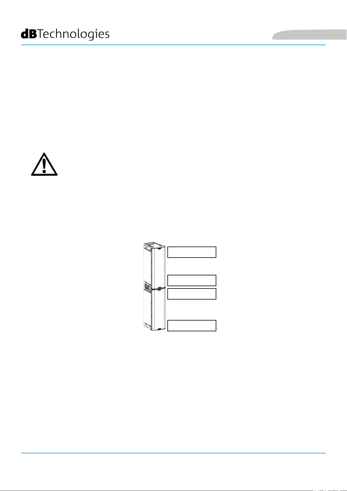
UTILIZZO DI UNA COPPIA DI DUE DIFFUSORI IG2T IN COLONNA
Per il corretto montaggio meccanico di due diffusori IG2T, uno sull’altro, è necessario ricorrere ad una coppia di
staffe di collegamento LP-IG. Per ogni ulteriore dettaglio consultare le istruzioni di questo accessorio.
Una volta che i due diffusori sono correttamente montati, il riconoscimento a infrarossi presente sulle
maniglie agisce automaticamente, occorre solamente effettuare il check nei menu iniziali della
congurazione che sarà presentato nel seguente capitolo.
ATTENZIONE!
• E’ possibile montare, far dialogare e riconoscere tramite le porte ad
infrarossi solo 2 diffusori identici.
• Non utilizzare mai le maniglie per appendere il diffusore!
LATO INFERIORE
LATO SUPERIORE
LATO SUPERIORE
LATO INFERIORE
INGENIA IG2T Cod. 420120238 REV. 1.1
16
Page 17
Italiano
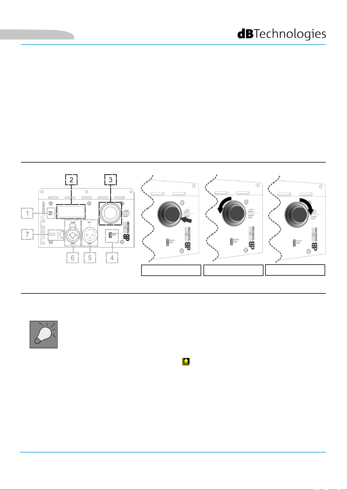
3. PANNELLO DI CONTROLLO E MENU DI SETTAGGIO
ACCESSO AI MENU
Il push rotary encoder (3) permette sia di operare una selezione, ruotandolo, sia di operare una conferma,
se premuto. Queste selezioni e conferme permettono di navigare fra i menu, visibili sul
display OLED (2). All’interno dei menu, la rotazione a destra o sinistra permette anche un incremento o
decremento dei valori selezionati.
SELEZIONE / DECREMENTOCONFERMA
Esempi di utilizzo del push rotary encoder
La schermata iniziale dopo l’accensione mostra il livello di IG2T. È possibile proteggere tutte le
impostazioni attraverso una password. Per conoscere tutti i dettagli relativi, consultare il paragrafo Menu Options.
• Una volta effettuate le impostazioni manualmente, queste rimangono
memorizzate anche dopo lo spegnimento del diffusore.
• Dopo circa un minuto che non ci sono selezioni o conferme, il sistema ritorna
alla schermata iniziale. Lo stesso ritorno può essere effettuato volutamente da
qualsiasi punto, in 2 modi:
A. selezionando e confermando il simbolo
B. tenendo premuto il push rotary encoder per qualche secondo.
• Se i diffusori sono 2, montati correttamente uno sull’altro, il sistema li riconosce
ed è quindi possibile controllarli entrambi agendo sul rotary di uno solo
(mirroring OLED).
All’accensione dell’IG2T, il display si attesta sulla schermata iniziale, che mostra il GAIN e il livello di
segnale VU METER.
SELEZIONE / INCREMENTO
INGENIA IG2T Cod. 420120238 REV. 1.1
17
Page 18
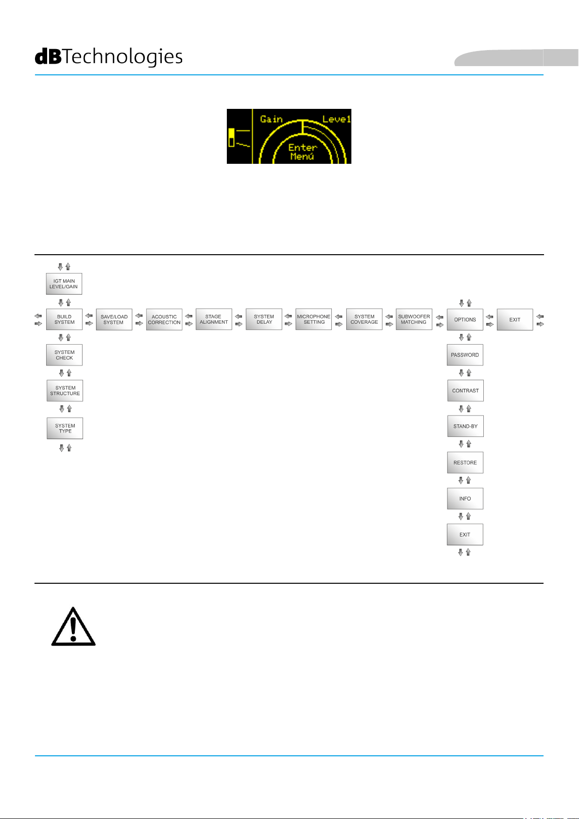
Da questa schermata, premendo il rotary push encoder, si accede ai vari menu, di cui è riportata la
struttura generale nella gura sottostante.
Italiano
Struttura dei Menu
ATTENZIONE!
• Il menu “SYSTEM COVERAGE” è visibile solo quando il sistema abbia
riconosciuto automaticamente, attraverso le porte a infrarossi presenti
sulle maniglie, che vi sono 2 diffusori sovrapposti.
• Il menu “SUBWOOFER MATCHING” è visibile solo quando si sia
selezionata la presenza di un subwoofer nelle impostazioni.
INGENIA IG2T Cod. 420120238 REV. 1.1
18
Page 19
Italiano
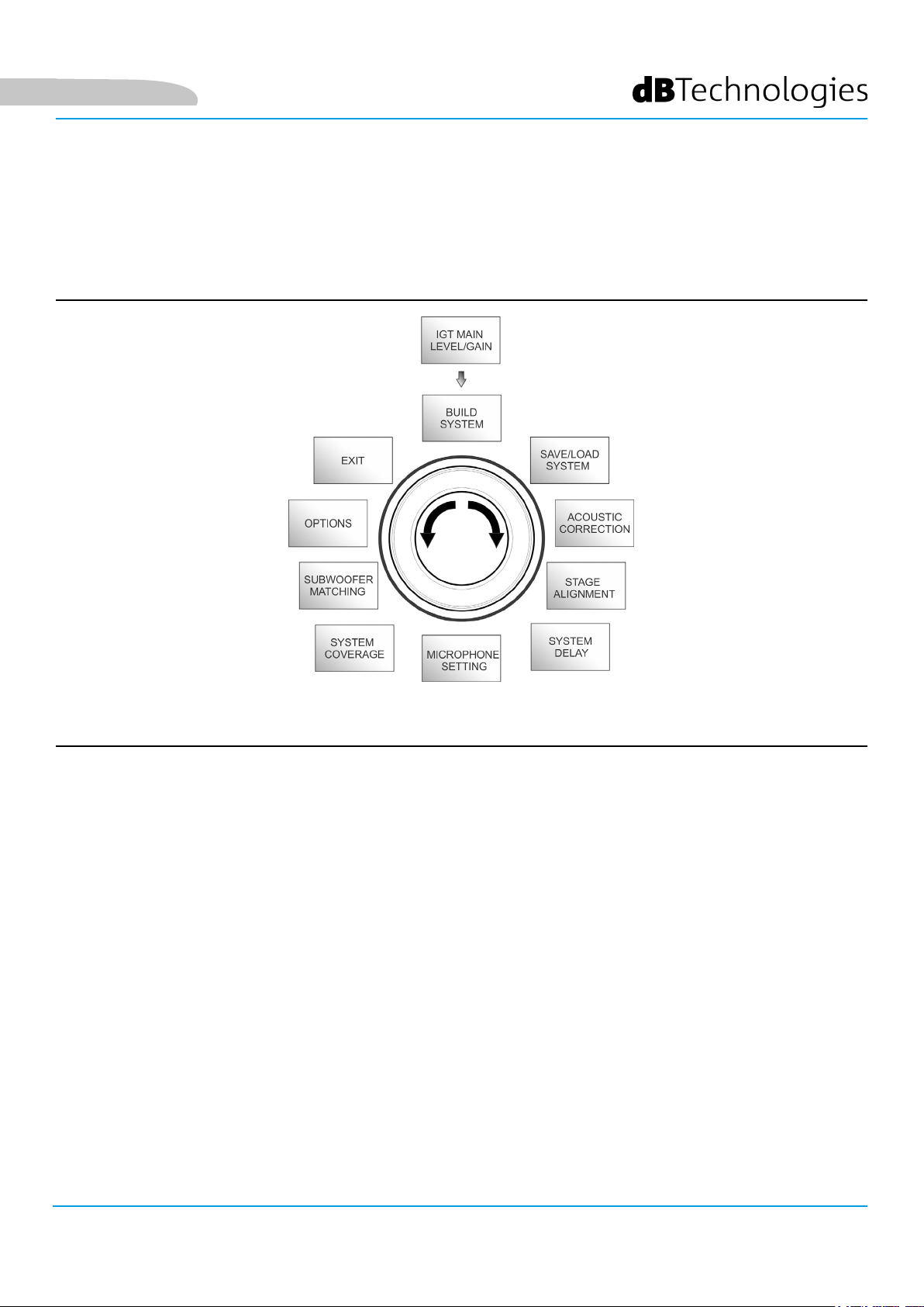
La struttura dei menu principali può essere rappresentata circolarmente, il push rotary encoder consente di
scorrerla sia con rotazione a sinistra che a destra. Vedi gura sottostante.
Rappresentazione circolare dei menu
INGENIA IG2T Cod. 420120238 REV. 1.1
19
Page 20
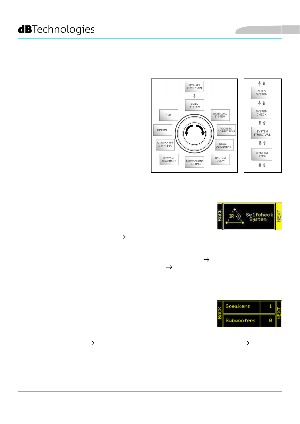
IL MENU BUILD SYSTEM
Questo menu congura automaticamente il sistema in
base al numero di diffusori, alla presenza o meno di un
subwoofer, alla posizione ed inclinazione dei diffusori
stessi. È composto da 3 sottomenu:
• SYSTEM CHECK
• SYSTEM STRUCTURE
• SYSTEM TYPE
Italiano
Build System Menu
Sottomenu
SYSTEM CHECK
Il sistema è in grado di rilevare, tramite la comunicazione a infrarossi (le porte di
comunicazione sono sulle maniglie dei diffusori) se l’utente sta utilizzando uno o
due diffusori IG2T. Una volta entrati in questa schermata:
1. Ruotare il rotary encoder selezionando Selfcheck System e confermare la scelta premendo il push rotary
encoder.
2. Dopo una breve animazione, il sistema passa automaticamente al menu successivo (SYSTEM STRUCTURE).
3. Se non è necessario effettuare questa operazione, selezionare e confermare NEXT, se è necessario
ritornare alla schermata pricipale, selezionare e confermare BACK.
SYSTEM STRUCTURE
Il menu permette di aggiornare manualmente il numero di subwoofer nella
congurazione che state utilizzando. Se è necessario aggiornare il numero di
subwoofer connessi.
1. Ruotare il rotary selezionando la voce “subwoofer” e confermarla.
2. Selezionare e confermare il numero di subwoofer che si intende utilizzare.
3. Selezionare e confermare NEXT per passare al menu successivo, selezionare e confermare BACK per
ritornare al sottomenu SYSTEM CHECK.
INGENIA IG2T Cod. 420120238 REV. 1.1
20
Page 21
Italiano
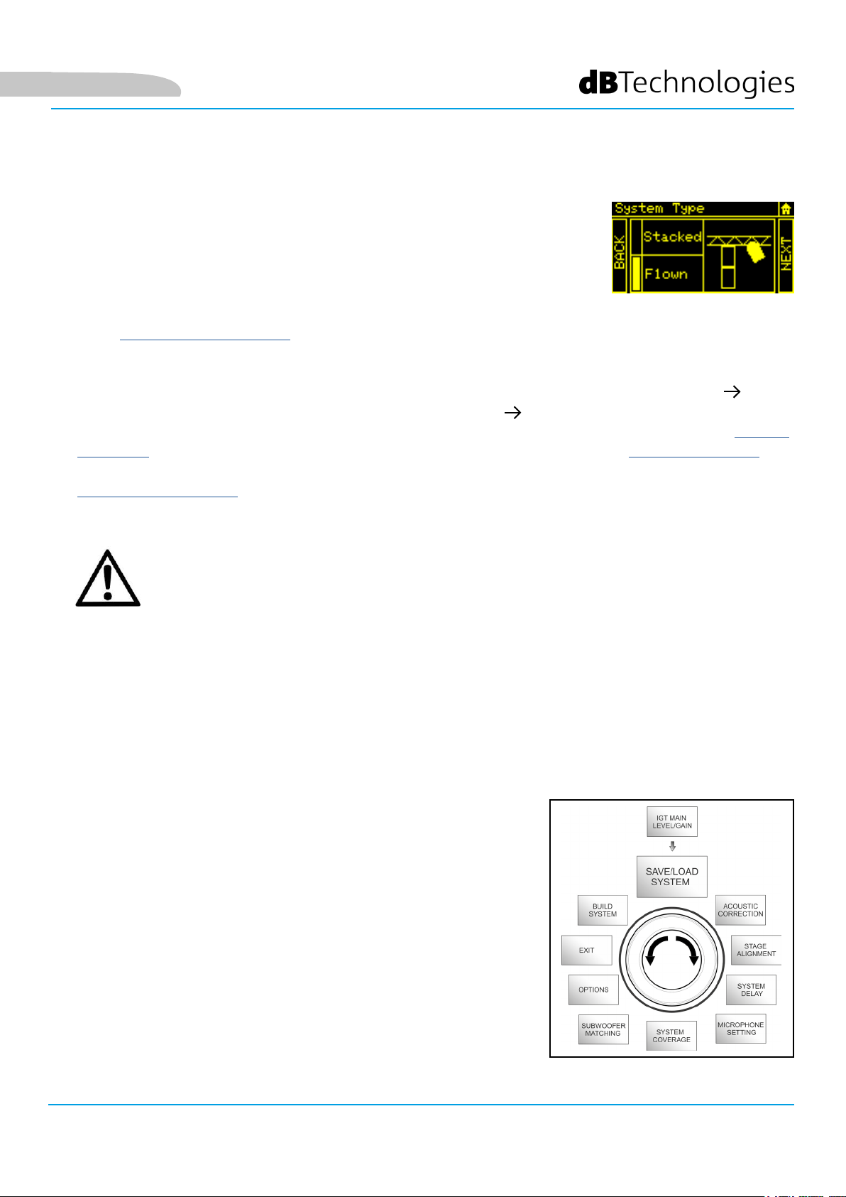
SYSTEM TYPE
Le tipologie di sistema che sono previste utilizzando l’IG2T sono 2:
• Stacked
• Flown
In congurazione “Stacked” uno o 2 diffusori IG2T possono essere in appoggio su stand o subwoofer (confrontare
il capitolo ESEMPI DI INSTALLAZIONE).
In congurazione “Flown”, invece, uno o due diffusori IG2T sono appesi.
Una volta entrati nel menu SYSTEM TYPE:
• Selezionare e confermare la modalità desiderata fra “Stacked” e “Flown”, selezionare e confermare NEXT
per accedere alla schermata successiva (selezionare e confermare BACK per ritornare a quella precedente).
A questo punto, se in precedenza il sistema ha rilevato la presenza di 2 diffusori, si accederà al menu SYSTEM
COVERAGE, e se si è selezionata la presenza di un woofer nel precedente sottomenu SYSTEM STRUCTURE, si
accederà poi al menu
• SUBWOOFER MATCHING, in caso contrario (Speakers 1, Subwoofer 0) la schermata successiva sarà quella
iniziale, e la procedura sarà terminata.
ATTENZIONE!
• Non installare mai il diffusore in appoggio diretto a terra, utilizzare
sempre uno stand opzionale (non fornito) con palo standard diametro
35 mm e treppiede con piede centrale posizionato in avanti. Vericare
sempre l’effettiva stabilità dell’installazione.
• Il modello INGENIA IG2T in montaggio “Stacked” su stand a treppiede
non può essere montato in congurazione a 2 diffusori sovrapposti, ma
esclusivamente a diffusore singolo, per motivi di sicurezza.
IL MENU SAVE/LOAD SYSTEM
Questo menu permette di salvare e successivamente richiamare le
congurazioni di utilizzo del sistema. Sebbene allo spegnimento l’IG2T
conservi tutte le informazioni delle ultime impostazioni effettuate, può
essere molto utile avere a disposizione, per contesti diversi, altrettante
impostazioni salvate in precedenza e poterle richiamare velocemente.
A questo scopo l’IG2T consente di salvare e nominare 5 settaggi con
la funzione “SAVE” e di richiamarli con la funzione “RECALL”. Nel caso
sia necessario poi modicare i settaggi presenti in una delle locazioni
di memoria, è possibile sovrascrivere successivamente le locazioni
precedentemente salvate.
Save/Load Menu
INGENIA IG2T Cod. 420120238 REV. 1.1
21
Page 22
Italiano
Per salvare un’impostazione dei vari parametri, accedere al menu SAVE/LOAD SYSTEM e:
1. selezionare e confermare il numero di una delle locazioni di memoria, da 1 a 5.
2. selezionare e confermare “SAVE”.
3. assegnare un titolo alla locazione. È possibile utilizzare un titolo alfanumerico no a 14 lettere/cifre. Si
seleziona e quindi conferma una lettera alla volta a anco del numero di locazione. Quando si vuole
terminare il titolo è sufciente confermare il carattere di spazio vuoto (_).
4. Premere “OK” alla schermata successiva.
5. Il sistema salva quindi le impostazioni nel numero di locazione col titolo prescelto.
Per richiamare un’impostazione, caricandola nel sistema:
1. Selezionare e confermare la locazione di memoria desiderata.
2. Selezionare e confermare “RECALL”.
3. Premere “OK” alla schermata successiva.
4. Il sistema ha caricato le impostazioni relative alla locazione di memoria desiderata ed è ritornato alla
schermata principale.
Per sovrascrivere un’impostazione su una precedente basta selezionare una locazione preesistente e selezionare e
confermare “OK” alla schermata di conferma di overwrite.
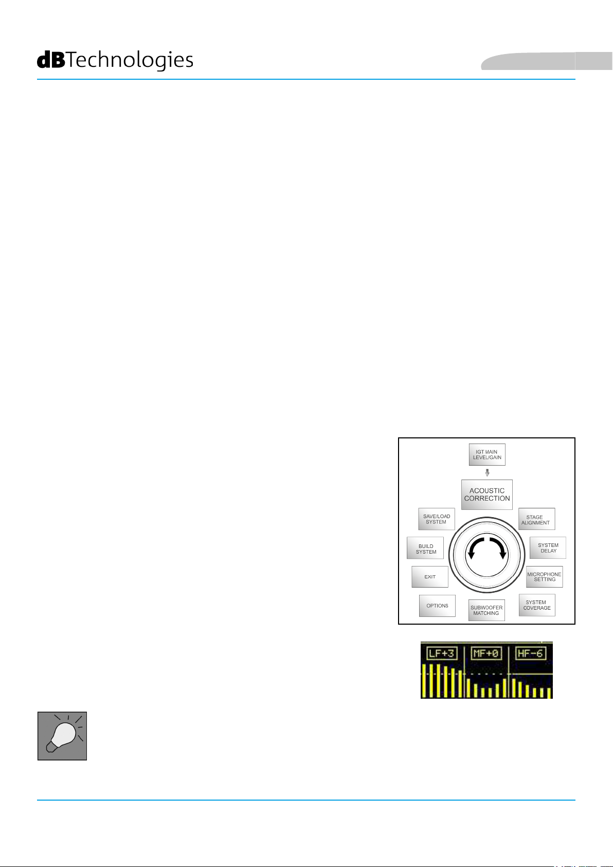
IL MENU ACOUSTIC CORRECTION
In diverse occasioni può rivelarsi utile effettuare un’equalizzazione
differenziata del segnale di uscita dal diffusore.
Il DSP presente nell’IG2T gestisce anche quest’opzione.
A questo scopo accedere al menu ACOUSTIC CORRECTION e:
1. selezionare e confermare la banda di frequenza su cui occorre
effettuare la correzione. È possibile agire su 3 bande:
A. LF - Low Frequency, con correzione + 3dB - 6 dB e
risoluzione da 0.5 dB
B. MF - Medium Frequency, con correzione + 0 dB - 6
dB e risoluzione da 0.5 dB
C. HF - High Frequency, con correzione + 3 dB – 6dB e
risoluzione da 0.5 dB
2. selezionare e confermare il livello di correzione desiderata.
3. se è necessario ripetere l’operazione per altre bande ritornare al punto 1,
altrimenti selezionare il simbolo di home e ritornare alla selezione dei menu
principali
Acoustic Correction Menu
• L’acoustic correction può essere usata per migliorare l’intelligibilità o
attenuare frequenze che risultino predominanti. Non sostituisce una
corretta disposizione dei diffusori, che va valutata tenendo conto
delle caratteristiche acustiche dell’ambiente.
INGENIA IG2T Cod. 420120238 REV. 1.1
22
Page 23
Italiano
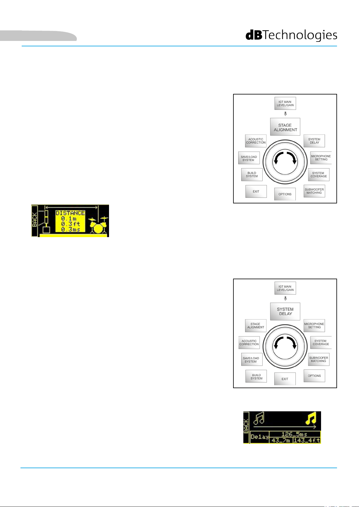
IL MENU STAGE ALIGNMENT
In una situazione live in cui siano presenti diverse fonti di amplicazione,
come amplicatori per chitarre sul palco, o sorgenti acustiche naturali
come una batteria, è possibile “allineare” virtualmente i diffusori IG2T,
indicando la distanza in metri o piedi a cui si trovano queste sorgenti.
In questo modo si otterrà un unico fronte d’onda acustica senza ritardi,
in tutti quei contesti live in cui questo è necessario. Per effettuare una
regolazione di questo tipo, dopo aver effettuato l’accesso al menù STAGE
ALIGNMENT:
1. selezionare e confermare il campo “DISTANCE”.
2. selezionare e conferm are il valore desiderato di distanza con range
0-15 m e risoluzione di 20 cm.
3. Ritornare alla schermata iniziale selezionando il simbolo “HOME”.
Stage Alignment Menu
IL MENU SYSTEM DELAY
In caso di utilizzo delle IG2T in ambienti che richiedano più stadi di
amplicazione replicati a distanze diverse, è possibile ritardare
appositamente il segnale in uscita dai diffusori, in modo che
l’ascoltatore percepisca un unico fronte d’onda in qualsiasi punto
della sala. Si pensi ad esempio alla copertura di un ambiente indoor
particolarmente ampio e lungo.
Per effettuare questo tipo di regolazione, dopo aver effettuato l’accesso al
menu SYSTEM DELAY:
1. selezionare e confermare il campo “DELAY”.
2. 2. selezionare e confermare il valore di ritardo desiderato con range
0-126 ms in termini di tempo o 0-43,7 m / 0-143,4 ft (piedi) in termini
di distanzaRitornare alla schermata iniziale selezionando il simbolo
“HOME”.
3. Ritornare alla schermata iniziale selezionando il simbolo “HOME”.
System Delay Menu
INGENIA IG2T Cod. 420120238 REV. 1.1
23
Page 24
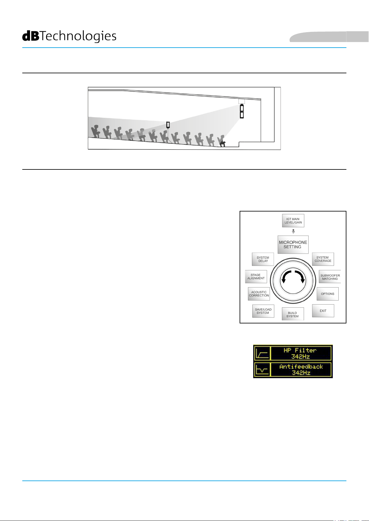
Settaggio per ambienti ampi e lunghi
IL MENU MICROPHONE SETTING
L’IG2T permette l’ingresso di un microfono con connettore XLR. Nel
contesto di utilizzo di questa sorgente, può essere utile applicare un
ltraggio al segnale per eliminare frequenze indesiderate (con un ltro
passa-alto con frequenza di taglio regolabile). Oppure può rendersi
necessario intervenire (con un ltro notch con centro banda selezionabile)
per evitare un feedback (o effetto Larsen). Per effettuare una o entrambe
queste regolazioni, dopo aver effettuato l’accesso al menu MICROPHONE
SETTING:
Italiano
1. selezionare e confermare HP lter (ltro passa-alto).
2. selezionare e confermare il valore di frequenza di taglio del ltro
passa-alto, con range variabile 50 Hz – 200 Hz e risoluzione 10 Hz
(selezionare il valore “None” se si intende disattivare il ltro) .
3. selezionare e confermare “Antifeedback” (ltro anti-feedback o antieffetto Larsen).
4. selezionare e confermare il valore di frequenza di centro banda, con
range variabile 260 Hz – 15000 Hz e risoluzione di 10 Hz (selezionare il
valore “None” se si intende disattivare il ltro).
5. Ritornare alla schermata iniziale selezionando il simbolo “HOME”.
Microphone Setting Menu
INGENIA IG2T Cod. 420120238 REV. 1.1
24
Page 25
Italiano
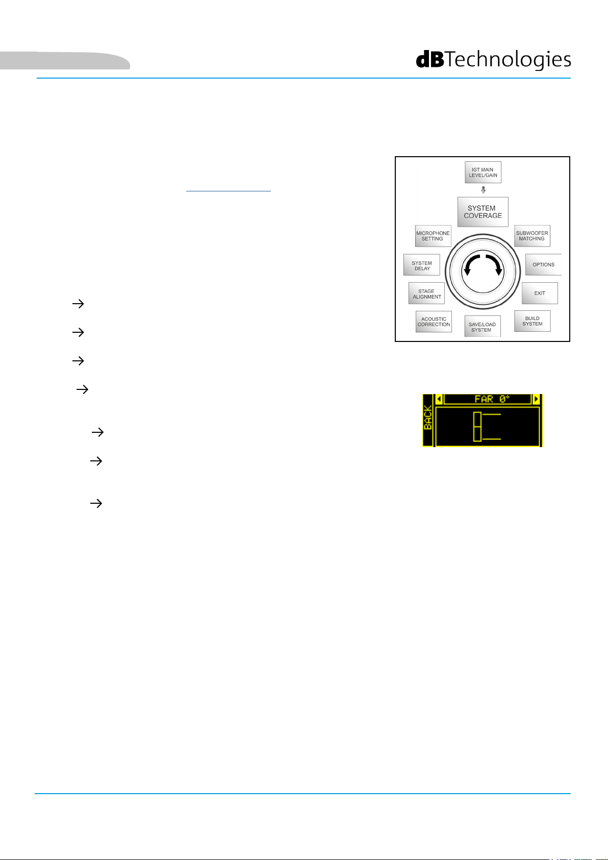
IL MENU SYSTEM COVERAGE
Per le funzionalità di questo menu, visibile solamente se nella fase di
SYSTEM CHECK il sistema ha riconosciuto automaticamente 2 diffusori,
confrontare anche il paragrafo “DIGITAL STEERING” nella sezione “ESEMPI
DI INSTALLAZIONE”.
Questo menu consente di modicare il fascio dell’onda emessa e la
copertura acustica relativa, una volta che il DSP abbia riconosciuto
l’installazione di 2 diffusori IG2T:
• UP +10° per un’installazione con necessità di copertura acustica
dal basso verso l’alto.
• UP +5° per dirigere il fronte d’onda con un’inclinazione media
verso l’alto.
• UP +2.5° per dirigere il fronte d’onda con una leggera inclinazione
verso l’alto.
• FAR 0° quando i diffusori devono arrivare il più lontano possibile,
in una situazione in cui siano installati frontalmente all’auditorio
all’altezza degli spettatori.
• DOWN -2.5° per dirigere il fronte d’onda con una leggera
inclinazione verso il basso.
• DOWN -5° da utilizzare per inclinare la copertura acustica verso
il basso (ad esempio pubblico non molto distante dai diffusiori e
installazione in sospensione).
• DOWN -10° per una direttività con la maggior angolazione
possibile verso il basso (ad esempio con un pubblico vicino e
un’installazione in sospensione).
System Coverage Menu
INGENIA IG2T Cod. 420120238 REV. 1.1
25
Page 26
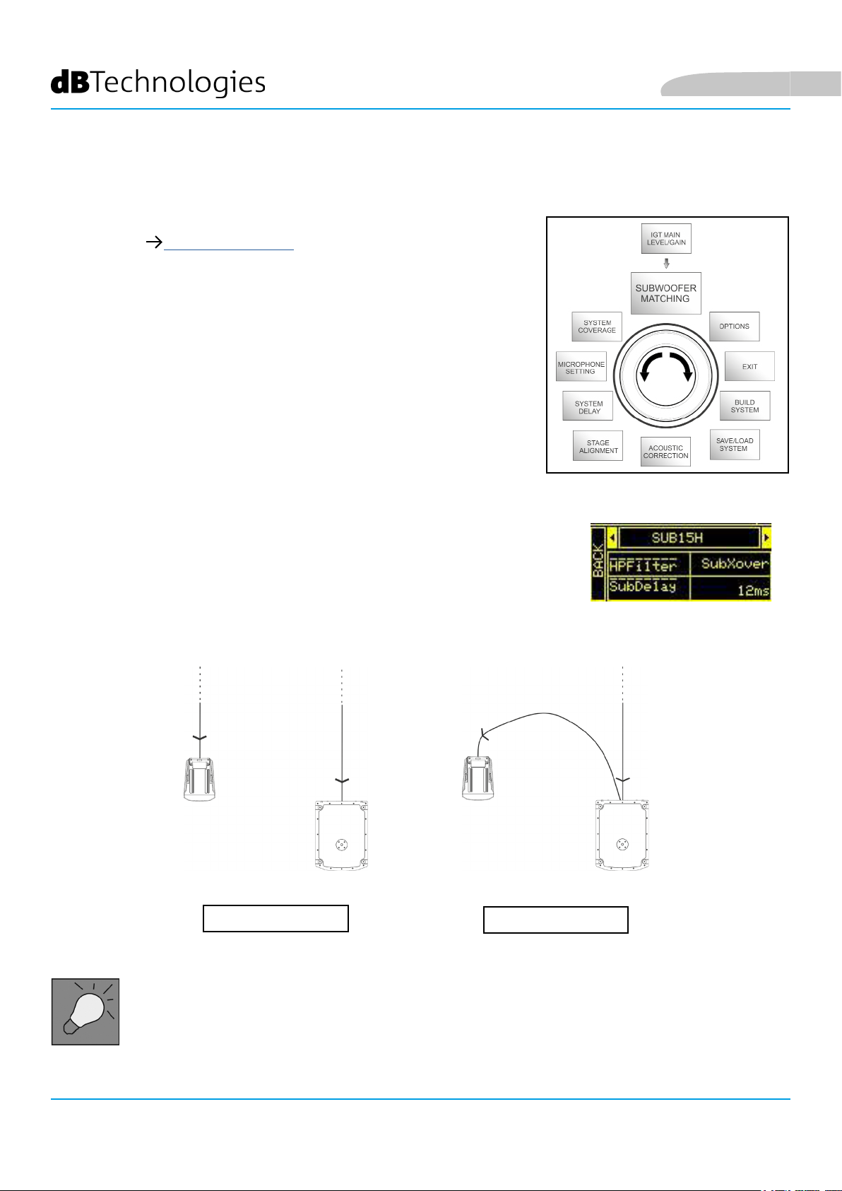
IL MENU SUBWOOFER MATCHING
Questo menu è visibile esclusivamente se in precedenza, nel sottomenu
BUILD SYSTEM SYSTEM STRUCTURE si è selezionata la presenza almeno
di un subwoofer. Inoltre, in questo caso, l’accesso a questo menu avviene
automaticamente dopo aver effettuato i settaggi di “SYSTEM TYPE” per
completare le impostazioni generali di sistema. Il menu consente
innanzitutto di identicare il subwoofer utilizzato. Permette poi di decidere
se utilizzare la sua frequenza di crossover o impostare una frequenza
selezionabile in base al modello (range massimo 70-120 Hz con risoluzione
5 Hz). Questa scelta dipende dal tipo di collegamento fra subwoofer e
diffusore, come mostrato nell’illustrazione sotto. Il menu fornisce anche il
suggerimento per il delay da impostare nel subwoofer. Per effettuare
la scelta della frequenza e del delay, dopo essere entrati nel menu
SUBWOOFER MATCHING:
1. selezionare e confermare il tipo di subwoofer associato
2. selezionare e confermare HpFilter e selezionare e confermare la
frequenza di crossover desiderata.
3. vericare per i settaggi dell’impianto qual è il valore di delay consigliato
per il subwoofer nel campo SubDelay.
4. selezionare “BACK” o “HOME” per ritornare rispettivamente alla scelta
dei menu o alla schermata principale.
Italiano
Subwoofer Matching Menu
COLLEGAMENTO DIRETTO
Se è necessario, si può impostare direttamente un valore di HpFilter su IG2T, senza utilizzare il
crossover di un subwoofer. Se invece si utilizza quest’ultimo:
a) in caso di COLLEGAMENTO DIRETTO, vericare la frequenza di crossover sul subwoofer, e
replicarla sull’IG2T impostando il relativo valore nel campo HpFilter.
b) In caso di collegamento XOVER DAL SUBWOOFER, settare “SubXover” nel campo HpFilter di IG2T.
XOVER DAL SUBWOOFER
INGENIA IG2T Cod. 420120238 REV. 1.1
26
Page 27
Italiano
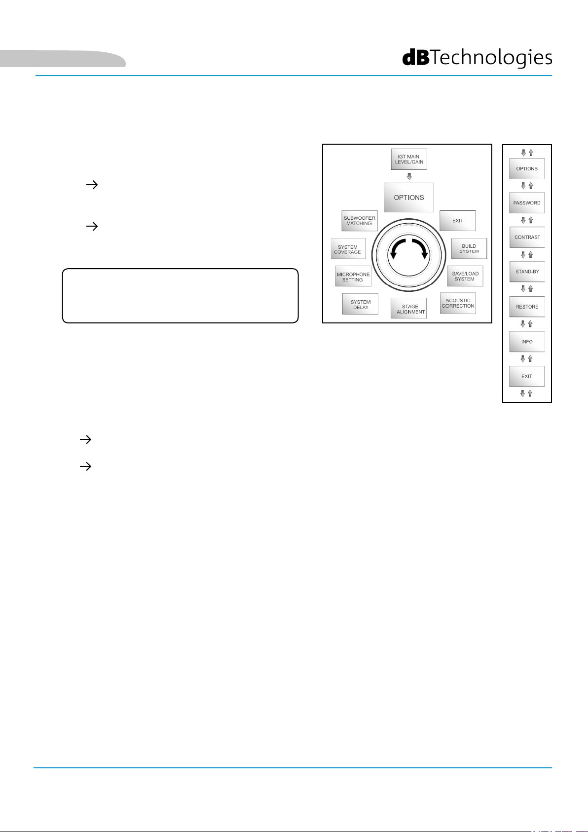
IL MENU OPTIONS
PASSWORD
1. ON/OFF (selezionare e confermare se si
desidera attivare/disattivare una protezione
delle impostazioni con password).
2. PASSWORD (possibilità, con selezione
e conferma, di immettere una password
alfanumerica no a 6 cifre/caratteri).
Per sbloccare il sistema in caso di smarrimento
(ON/OFF e scelta del codice)
SUPERUSER PASSWORD
della password: Q2R5D9.
Options Menu
CONTRAST
1. Selezionare e confermare per regolare il contrasto del display OLED con un’accentuazione
della luminosità da 0 a 100% e risoluzione del 5%.
STAND-BY
1. ON/OFF (selezionare e confermare se si desidera attivare/disattivare uno stand-by a
tempo del pannello di controllo).
2. PASSWORD (possibilità, con selezione e conferma, di immettere un valore temporale
dpo il quale il pannello di controllo entra in stand-by, variabile fra 0’:10’’ – 10’:00 e
risoluzione di 10’’).
(ON/OFF dello spegnimento automatico e scelta dell’intervallo di tempo)
RESTORE
1. Selezionare e confermare per attivare un ripristino alle impostazioni di fabbrica.
INFO
1. Selezionare e confermare per visualizzare le informazioni sull’ultima versione rmware
caricata.
EXIT
1. Selezionare e confermare per uscire dal menu OPTIONS.
INGENIA IG2T Cod. 420120238 REV. 1.1
27
Page 28
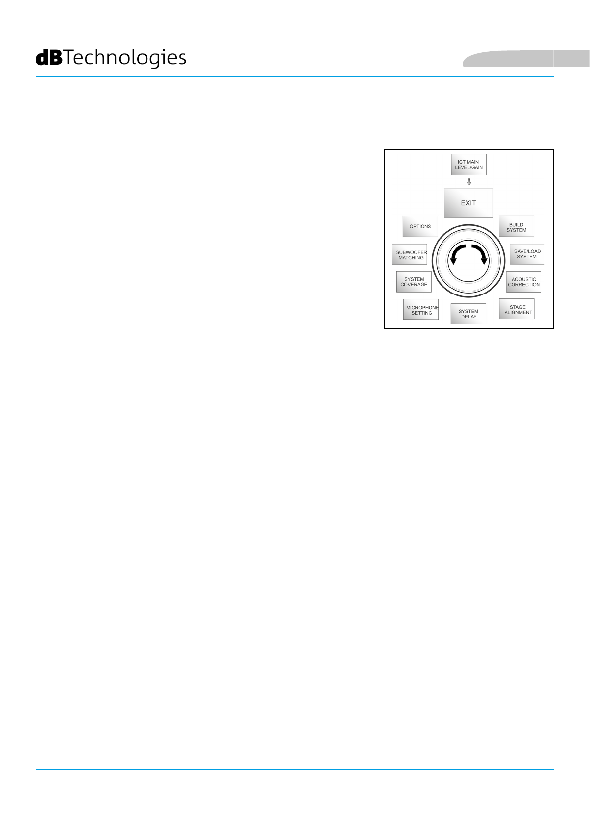
IL MENU EXIT
Questo menu permette, quando selezionato e confermato, di ritornare
alla schermata iniziale dell’IG2T.
Italiano
Exit Menu
INGENIA IG2T Cod. 420120238 REV. 1.1
28
Page 29
Italiano
4. ESEMPI DI INSTALLAZIONE
• Per utilizzare 2 diffusori l’uno sull’altro, occorre servirsi dell’accessorio opzionale LP-IG. Per ogni
ulteriore informazione, fare riferimento alle istruzioni di questo accessorio.
• Vericare sempre che le maniglie, che permettono la comunicazione a infrarossi, siano prive
di ostacoli nell’installazione per la comunicazione a infrarossi, evitare di coprirle e rimuovere
eventuale polvere o sporcizia che si possa depositare su di esse.
• Non sono ammessi tipi di installazione diversi da quelli qui illustrati.
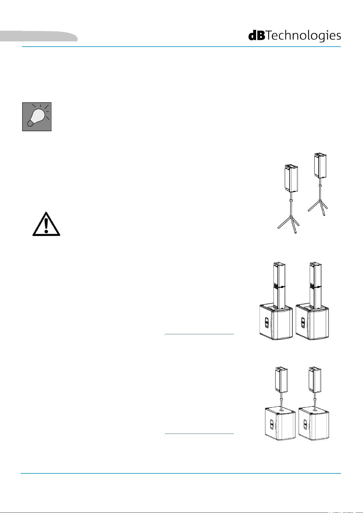
INSTALLAZIONE SU STATIVO
1 INGENIA IG2T è installabile su stativo a treppiede opzionale standard con palo
di diametro 35 mm. La massima altezza ammessa tra la base dello speaker e il
pavimento è 150 cm.
ATTENZIONE!
• Utilizzare uno stand dimensionato opportunamente con il piede
centrale in avanti per assicurare una stabilità adeguata.
• Il modello INGENIA IG2T in montaggio “Stacked” su stand non
può essere montato in congurazione a 2 diffusori sovrapposti,
ma esclusivamente a diffusore singolo, per motivi di sicurezza.
INSTALLAZIONE SU SUBWOOFER
Tramite installazione con l’accessorio GSA-IG, è possibile utilizzare i diffusori (1 o 2)
montati su subwoofer. In questo modo si può ottenere un sistema estremamente
compatto e potente su tutte le frequenze acustiche con installazione a terra.
E’ necessario un ssaggio meccanico addizionale, o un ssaggio con cinghie,
per assicurare correttamente l’installazione. Seguire le istruzioni relative alla
congurazione del subwoofer relativa alla sezione SUBWOOFER MATCHING una
volta completata l’installazione.
INSTALLAZIONE SU SUBWOOFER CON PALO
E’ possibile l’utilizzo di un solo speaker montato su palo diametro 35 mm. La
massima altezza ammessa tra la base dello speaker e il pavimento è 150 cm.
E’ necessario un ssaggio meccanico addizionale, o un ssaggio con cinghie
per assicurare correttamente l’installazione. Seguire le istruzioni relative alla
congurazione del subwoofer relativa alla sezione SUBWOOFER MATCHING una
volta completata l’installazione.
INGENIA IG2T Cod. 420120238 REV. 1.1
29
Page 30
INSTALLAZIONE A TERRA
E’ possibile un’installazione a terra di 1 o 2 INGENIA IG2T tramite l’accessorio
GSA-IG. E’ necessario un ssaggio meccanico con viti o tasselli adeguati al tipo di
pavimentazione.Per ogni ulteriore informazione consultare i manuali relativi agli
accessori.
INSTALLAZIONE IN SOSPENSIONE
Per congurazione own, si considera la sospensione di 1 o 2 diffusori IG2T,
con l’accessorio opzionale DRK-IG, il quale permette l’utilizzo di un grillo. La
combinazione DRK-IG con il truss adapter TA-IG rende possibile il montaggio su una
struttura specica, come un’americana. In sospensione, è utilissimo utilizzare i rilanci
sia di alimentazione, sia di segnale, per ottenere una riduzione della complessità dei
collegamenti, come mostrato nella sezione “PRIMA ACCENSIONE”.
Italiano
ATTENZIONE!
• In contesti di utilizzo all’aperto, ancorare il diffusore per evitare
oscillazioni dovute agli agenti atmosferici e al vento.
• Non utilizzare mai le maniglie per appendere il diffusore!
INSTALLAZIONE A MURO CON STAFFE
INGENIA IG2T può essere installata a muro tramite le staffe opzionali WB-IG2.
Curare il posizionamento in modo da ottenere la copertura ottimale. Tenere
conto, in caso di doppio speaker verticale correttamente installato (è obbligatorio
in questo caso l’utilizzo di LP-IG), della possibilità di utilizzare la tecnologia del
digital steering (vedi paragrafo). Consultare le istruzioni di WB-IG2 per ulteriori
informazioni.
INGENIA IG2T Cod. 420120238 REV. 1.1
30
Page 31

Italiano
IL DIGITAL STEERING
Il digital steering è una tecnologia che può essere
opportunamente adottata per direzionare la copertura
acustica di due diffusori sovrapposti, modicandola in base
alle esigenze del contesto di utilizzo e dell’installazione. Il DSP
dell’INGENIA IG2T rende il fronte d’onda acustica di 2 diffusori
sovrapposti come quello di un unico diffusore angolato, come
mostrato in gura. In fase di setup, riconosciuti i 2 diffusori
tramite le porte a infrarossi presenti sulle maniglie, è possibile
modicare la copertura acustica tramite un apposito menu
SYSTEM COVERAGE (altrimenti invisibile se il diffusore è in
congurazione singola):
Platea
Per ogni informazione ulteriore fare riferimento alla sezione
IL MENU SYSTEM COVERAGE.
Inclinazione
INGENIA IG2T Cod. 420120238 REV. 1.1
31
Page 32

Italiano Italiano
5. AGGIORNAMENTO DEL FIRMWARE
È molto importante mantenere aggiornato il rmware del prodotto, per garantirne una piena funzionalità.
Controllare periodicamente il sito http://www.dbtechnologies.com nella sezione “DOWNLOADS”. Una volta che si
sia vericata la presenza di una versione di rmware nuova:
1. Scaricare l’USB BURNER MANAGER nella sezione “SOFTWARE & CONTROLLER”.
2. Scaricare il le .zip dell’ultimo rmware nella sezione “DOWNLOADS” relativa all’INGENIA IG2T.
3. Nella schermata dell’USB BURNER MANAGER, in alto a destra, selezionare “File Opening”.
4. Selezionare il le del rmware precedentemente scaricato (vericando la correttezza in base al proprio
sistema operativo).
5. Cliccare UPDATE.
ATTENZIONE!
Aggiornando il rmware non è garantita la presenza delle vecchie
impostazioni salvate alla successiva accensione del prodotto.
INGENIA IG2T Cod. 420120238 REV. 1.1
32
Page 33

6. RISOLUZIONE DEI PROBLEMI
Il diffusore non si accende:
1. Vericare la corretta presenza dell’alimentazione a monte dell’impianto.
2. Vericare che il cavo di alimentazione con connettore Neutrik® powerCON TRUE1® sia correttamente
inserito.
Il diffusore si accende ma non emette nessun suono:
1. Vericare che i collegamenti in ingresso del segnale audio siano correttamente effettuati con cavi con
con connettori Neutrik®.
2. Vericare che i cavi utilizzati non siano danneggiati.
3. Vericare che il mixer o la sorgente audio sia accesa e mostri chiaramente la presenza di segnale in
uscita.
4. Vericare che il livello del guadagno nella schermata iniziale sia impostato a un valore adeguato.
ItalianoItaliano
Il diffusore risulta collegato, ma il pannello di controllo appare totalmente spento, schermo
OLED compreso:
1. Ruotare il push rotary encoder per riattivare un’eventuale situazione di stand-by del display
precedentemente inserita.
2. Vericare che il cavo di alimentazione con connettore Neutrik® powerCON TRUE1® sia correttamente
inserito.
3. Vericare che non manchi l’alimentazione a monte dell’impianto.
Il diffusore emette un suono distorto:
1. Regolare per primo il volume della sorgente, poi portare il guadagno di ingresso dell’IG2T a un valore
adeguato.
2. Vericare che i cavi utilizzati non siano danneggiati, nel qual caso sostituirli (un cavo danneggiato può
portare a perdita o alterazione del segnale).
3. Vericare le impostazioni dei menu che inuiscono sul contenuto in frequenza del segnale in uscita e in
particolare:
a) ACOUSTIC CORRECTION
b) MICROPHONE SETTING se in ingresso è collegato un microfono
INGENIA IG2T Cod. 420120238 REV. 1.1
33
Page 34

Italiano
Il sistema non riconosce 2 diffusori sovrapposti, e nella schermata SYSTEM STRUCTURE compare 1 solo speaker:
1. Vericare di aver montato correttamente i 2 diffusori, uno sull’altro, con quello superiore capovolto, e
di aver utilizzato e ssato correttamente le staffe di collegamento LP-IG come da istruzioni di questo
accessorio.
2. Vericare che le maniglie superiori e inferiori dei diffusori, che contengono le porte di comunicazione a
infrarossi, non siano in nessun modo coperte.
Eseguire nuovamente la procedura di “Selfcheck System” all’interno di SYSTEM CHECK, come mostrato
nel paragrafo relativo.
Non è possibile modicare le impostazioni dei vari menu del pannello di controllo, pur essendo il diffusore
chiaramente acceso:
1. Vericare l’eventuale presenza di una password di blocco precedentemente impostata.
2. Vericare la funzionalità in rotazione e pressione del push rotary encoder.
Il diffusore emette un suono ritardato rispetto alla sorgente:
Italiano
1. Vericare le impostazioni dei menu che inuiscono sul ritardo del segnale audio e in particolare:
a) STAGE ALIGNMENT
b) SYSTEM DELAY
Il display non permette di vedere chiaramente le impostazioni dei menu:
1. Accedere al menu relativo alla regolazione della luminosità del display OPTIONS CONTRAST (vedi le
informazioni relative alla sezione IL MENU OPTIONS).
INGENIA IG2T Cod. 420120238 REV. 1.1
34
Page 35
Italiano
7. SPECIFICHE TECNICHE
GENERALE
Italiano
Tipologia:
DATI ACUSTICI
Risposta in frequenza [-10dB]:
Risposta in frequenza [-6dB]:
Max SPL:
HF compression diver (uscita):
HF Voice Coil:
Tipologia HF:
Direttività:
Frequenza di crossover:
Diffusore attivo a 2 vie a sviluppo verticale
59 - 20.000 Hz
63 – 19200 Hz
128 dB
1”
1.4” (Titanio)
Compression driver al neodimio
Verticale asimmetrica
1900 Hz
Copertura (HxV):
LF:
LF Voice coil:
Tipologia LF:
100° x 80° (+15°/-65°)
2 x 8”
2”
Neodimio
AMPLIFICATORE
Tipologia:
Classe di amplicazione:
INGENIA IG2T Cod. 420120238 REV. 1.1
Digipro® G3
Classe D
35
Page 36

Italiano
Potenza di amplicazione RMS:
Potenza di picco:
Interfaccia:
Display autorotativo:
Riconoscimento della posizione:
Controllo in mirroring (per 2
diffusori con controllo IR):
Corrente di inrush: 18,64 A
Push rotary encoder + OLED display
400 W
800 W
Sì
EPD
Sì
PROCESSORE
Controller interno:
Convertitore A/D D/A:
DSP 56 bit
24 bit/48 kHz
Impostazioni:
Limiter:
INGRESSI
Ingressi:
Uscite:
USB:
DIMENSIONI
Materiale:
Griglia:
Impostazioni di utilizzo di fabbrica e personalizzabili, salvabili e
richiamabili
Peak, RMS, Termico
1x Combo (XLR/Jack) bilanciato/sbilanciato
1x XLR link OUT
Mini USB di tipo B
Polipropilene PP rinforzato
Acciaio verniciato / lavorazione CNC
Predisposizione per y-bar:
INGENIA IG2T Cod. 420120238 REV. 1.1
Sì
36
Page 37

Italiano
Maniglie:
Montaggio su palo:
Larghezza:
Altezza:
Profondità:
Peso:
1 superiore / 1 inferiore con interfaccia IR
Sì, 36 mm
228 mm
646 mm
315 mm
12,8 kg
INGENIA IG2T Cod. 420120238 REV. 1.1
37
Page 38

Italiano
Caratteristiche, speciche e aspetto dei prodotti sono soggetti a possibili cambiamenti senza previa
comunicazione. dBTechnologies si riserva il diritto di apportare cambiamenti o miglioramenti nel design o nelle
lavorazioni senza assumersi l’obbligo di cambiare o migliorare anche i prodotti precedentemente realizzati.
A.E.B. Industriale Srl
Via Brodolini, 8
Località Crespellano
40053 VALSAMOGGIA
BOLOGNA (ITALIA)
Tel +39 051 969870
Fax +39 051 969725
www.dbtechnologies.com
info@dbtechnologies-aeb.com
INGENIA IG2T Cod. 420120238 REV. 1.1
38
Page 39

English
English
INDEX
1. GENERAL INFORMATIONS ....................................................................................................41
WELCOME! .........................................................................................................................41
PRELIMINARY OVERVIEW ..................................................................................................41
USER REFERENCES ..............................................................................................................41
MECHANICAL AND ACOUSTIC CHARACTERISTICS ............................................................42
DIMENSIONS .............................................................................................................................................. 42
ACOUSTIC COVERAGE ............................................................................................................................... 42
ACCESSORIES ............................................................................................................................................. 43
CHARACTERISTICS OF THE AMPLIFICATION AND CONTROL SECTION ............................44
INPUT AND CONTROL SECTION ................................................................................................................ 45
POWER SUPPLY SECTION .......................................................................................................................... 46
2. FIRST SWITCH-ON ..................................................................................................................47
PACKAGE CONTENTS ..........................................................................................................47
INSTALLATION .....................................................................................................................47
CONNECTING THE INPUTS ........................................................................................................................ 47
CONNECTING THE POWER SUPPLY .......................................................................................................... 48
CONNECTING OUTPUTS BETWEEN MULTIPLE MODULES (power supply linking) ................................. 49
CONNECTING OUTPUTS BETWEEN MULTIPLE MODULES (audio signal linking) .................................. 50
USE OF A PAIR OF STACKED IG2T SPEAKERS .......................................................................................... 51
3. CONTROL PANEL AND SETTING MENUS .............................................................................52
ACCESSING THE MENUS .....................................................................................................52
BUILD SYSTEM MENU ........................................................................................................55
SYSTEM CHECK .......................................................................................................................................... 55
SYSTEM STRUCTURE .................................................................................................................................. 55
SYSTEM TYPE ............................................................................................................................................. 56
SAVE/LOAD SYSTEM MENU ...............................................................................................56
ACOUSTIC CORRECTION MENU .........................................................................................57
STAGE ALIGNMENT MENU .................................................................................................58
SYSTEM DELAY MENU ........................................................................................................58
MICROPHONE SETTING MENU ..........................................................................................59
SYSTEM COVERAGE MENU ................................................................................................60
SUBWOOFER MATCHING MENU .......................................................................................61
OPTIONS MENU ..................................................................................................................62
PASSWORD ................................................................................................................................................ 62
CONTRAST .................................................................................................................................................. 62
STAND-BY ................................................................................................................................................... 62
RESTORE ..................................................................................................................................................... 62
INFO ........................................................................................................................................................... 62
EXIT............................................................................................................................................................. 62
EXIT MENU ..........................................................................................................................63
4. INSTALLATION EXAMPLES ....................................................................................................64
INSTALLATION ON STAND ..................................................................................................64
INGENIA IG2T Cod. 420120238 REV. 1.1
39
Page 40

English
INDEX
INSTALLATION ON SUBWOOFER .......................................................................................64
INSTALLATION ON SUBWOOFER WITH POLE ...................................................................64
FLOOR INSTALLATION ........................................................................................................65
FLOWN INSTALLATION .......................................................................................................65
INSTALLATION WITH WALL BRACKETS ..............................................................................65
DIGITAL STEERING ..............................................................................................................66
5. UPDATING THE FIRMWARE ..................................................................................................67
6. TROUBLESHOOTING ..............................................................................................................68
7. TECHNICAL SPECIFICATIONS ................................................................................................70
GENERAL .................................................................................................................................................................... 70
ACOUSTIC DATA ......................................................................................................................................... 70
AMPLIFIER .................................................................................................................................................. 70
PROCESSOR ................................................................................................................................................ 71
INPUTS........................................................................................................................................................ 71
DIMENSIONS .............................................................................................................................................. 71
INGENIA IG2T Cod. 420120238 REV. 1.1
40
Page 41

English
1. GENERAL INFORMATIONS
WELCOME!
Thank you for purchasing a product designed and developed in Italy by dBTechnologies! This vertical 2-way active
speaker is the result of years of experience and research on speakers, with the use of innovative solutions in the
eld of acoustics, electronics and research on materials.
PRELIMINARY OVERVIEW
INGENIA IG2T is a vertical 2-way speaker, equipped with two 8” woofers and one 1” compression driver exit (voice
coil: 1.4”), controlled by a latest generation 400 W RMS DIGIPRO G3 amplier. Its most innovative characteristics
include:
• an accurate design of the horn, featuring an asymmetric directivity, specically designed to provide
excellent acoustic coverage, ensuring an uncompromising sound denition in different indoor and
outdoor applications.
• digital steering controlled by the powerful internal DSP, with the use of 2 stacked speakers, allowing to
combine wider coverage and greater sound power with uncompromising accuracy and clarity.
• immediate automatic detection of the 2-speaker conguration, thanks to the infra-red communication
system installed on the handles (EPD technology) and to the fast, customizable, DSP-controlled
management. In this conguration the OLED displays orientate automatically. Just operating the
control section of one of the two speakers allows to drive the whole system.
• an innovative shape, with the use of 2 woofers and 1 driver, in a cabinet combining ruggedness, sound
performances, compactness and easy handling.
• extreme versatility, allowing to quickly and easily save and recall one’s settings, protecting them with a
settable password.
USER REFERENCES
To get the most from your INGENIA IG2T we recommend that you:
• thoroughly read the quick start user manual you will nd in the package and this manual, and keep it
throughout the product life.
• register the product on the site http://www.dbtechnologies.com, in the “SUPPORT” section.
• download and install the latest rmware from the Web site http://www.dbtechnologies.com, in the
“DOWNLOADS” section (see chapter UPDATING THE FIRMWARE).
• keep the proof of purchase and the WARRANTY (User manual - section 2).
INGENIA IG2T Cod. 420120238 REV. 1.1
41
Page 42

MECHANICAL AND ACOUSTIC CHARACTERISTICS
DIMENSIONS
INGENIA IG2T integrates, in a reinforced polypropylene cabinet
weighing 10.8 kg (28.22 lbs.), two 8” woofers and a one 1.4”
compression driver exit (voice coil: 1”) with neodymium
magnets featuring exceptional compactness, weight and
performances. Internally, a lightweight metal structure improves
mechanical rigidity and acoustic behaviour. The dimensions of
each individual speaker are: 228 x 646 x 315 mm (8.98 x 25.43 x
12.40 inches). The handles allow to easily transport it; the unit
can be displaced by a single person. Different congurations are
possible, e.g. mounting on subwoofer, possibility to suspend a
single or double speaker.
English
ACOUSTIC COVERAGE
The special opening of the horn, outlined in the gure,
ensures a total directivity of 100 x 80° (+15°/- 65°). This
asymmetric vertical directivity ensures excellent sound
coverage, in indoor and outdoor contexts. Using 2 stacked
IG2Ts, you can also control with the digital steering the full
coverage of the speakers. This allows, even installing the
IG2Ts vertically, to achieve the effect of a single inclined
speaker, with all the ensuing benets in terms of directivity.
INGENIA IG2T Cod. 420120238 REV. 1.1
42
Page 43

English
ACCESSORIES
The following optional accessories are available for quick installation:
• Fly-bar DRK-IG (and the optional TA-IG) for vertical own installation.
• LP-IG locking bracket pair allowing to fasten 2 stacked IG2T modules.
• Optional GSA-IG stand for installation on subwoofer (or on the oor).
• Wall bracket WB-IG2 for xed installation on wall.
• A specially designed bag (TC-IG2T) and a rain cover (RC-M1) are available for speaker transport and
protection.
Fly Bar DRK-IG LP-IG Locking Bracket
TA-IG truss adapter
WARNING!
• Never use the handles to suspend the speaker!
For further information please refer to the relevant manuals.
GSA-IG stand
WB-IG2
INGENIA IG2T Cod. 420120238 REV. 1.1
43
Page 44

CHARACTERISTICS OF THE AMPLIFICATION AND CONTROL SECTION
The D-class latest generation digital amplier DIGIPRO G3 is the
core of IG2T and can provide a sound power of 400 W RMS.
Thanks to a switching power supply section featuring a
particularly efcient auto-range function, the system is quiet,
as it requires no active cooling system. The system is controlled
by a powerful DSP, allowing to dene different parameters, as
well as to automatically manage the communication between
the modules, in case of conguration with 2 stacked speakers.
In the latter case, the DSP individually controls the acoustic
components, to obtain a congurable directional sound focus
(digital steering).
ATTENTION!
• Protect the module from humidity.
• Never try to open the amplier.
• In case of malfunction, immediately cut
off the power supply, by disconnecting the
module from the mains, then contact an
authorised repairman.
English
CONTROL SECTION
AMPLIFIER INPUT AND
The DIGIPRO G3 panel consists of:
• INPUT AND CONTROL SECTION
• AMPLIFIER
• POWER SUPPLY SECTION
SECTION
POWER SUPPLY
INGENIA IG2T Cod. 420120238 REV. 1.1
44
Page 45

English
INPUT AND CONTROL SECTION
1. “PEAK” LED
Red LED that lights up briey when connecting power or in
case of audio limiter operation
ATTENTION!
Never use the speaker for a prolonged
time while the limiter LED is on or
blinking, indicating the equipment is
running under excessive stress conditions
with distorted sound.
2. OLED DISPLAY
The display automatically orientates according to the
accelerometer control, detecting whether the speaker has been installed
straight vertically or ipped. The user can congure a contrast adjustment and automatic power-off function (see
chapter CONTROL PANEL AND SETTING MENUS).
3. PUSH ROTARY ENCODER
The push rotary encoder allows both a rotary selection (selection of menus and values), and a push selection
(selection conrmation) to navigate the menus.
4. USB SERVICE DATA
The type B mini-USB B port allows to update the product rmware. For further information, please refer to
the Web site http://www.dbtechnologies.com in the “DOWNLOADS” section and to chapter UPDATING THE
FIRMWARE)
ATTENTION!
The USB SERVICE DATA connection must only be used to update the
product rmware; never connect any USB device to the equipment, to
avoid possible damages or malfunctions.
5. “LINK” OUTPUT
Balanced “XLR” output, allowing to send the input audio signal to another amplied speaker.
6. “INPUT” COMBO INPUT
Combined XLR-TR-TRS audio signal input. It allows to use a balanced XLR connector, or a ¼” TS or TRS jack input.
ATTENTION!
Only use cables equipped with high-quality Neutrik® original
connectors. Using different or poor-quality connectors might affect
the speaker operation.
7. “INPUT SENSITIVITY” SELECTOR
A selector allowing to set whether the incoming signal comes from a mixer/a line (“LINE”) or from a microphone
(“MIC”).
INGENIA IG2T Cod. 420120238 REV. 1.1
45
Page 46
POWER SUPPLY SECTION
English
8. “AUTO-RANGE MAINS INPUT” POWER SUPPLY INPUT
Input for Neutrik® powerCON TRUE1® connector.
9. “MAINS LINK” POWER SUPPLY LINKING OUTPUT
The connection provided by Neutrik® NAC3PX allows to link the power supply to a second module.
10. “MAINS FUSE” PROTECTION FUSE
Mains fuse
ATTENTION!
The speaker is supplied equipped with a pre-installed fuse designed to
operate within the 220-240 V range. If the system must operate within the
100-120 V range:
1. Disconnect all connections, including the power supply one
2. Wait 5 minutes.
3. Replace the fuse with the one included in the package for the 100-120 V range.
4. Only use the provided power cord.
INGENIA IG2T Cod. 420120238 REV. 1.1
46
Page 47

English
2. FIRST SWITCH-ON
PACKAGE CONTENTS
Open the package and check that the INGENIA IG2T speaker packaging contains all the items included in the
supply. The packaging includes:
• power cord with connector Neutrik® TRUE powerCON TRUE1®
• INGENIA IG2T
• quick start and warranty-related documents
• fuse to be installed if the system is to operate within the 100-120V range
ATTENTION!
The speaker is supplied equipped with a pre-installed fuse designed to
operate within the 220-240 V range. If the system must operate within the
100-120 V range:
1. Disconnect all connections, including the power supply one
2. Wait 5 minutes.
3. Replace the fuse with the one included in the package for the 100-120 V range.
4. Only use the provided power cord.
INSTALLATION
CONNECTING THE INPUTS
MIXER / LINE MICROPHONE
INGENIA IG2T Cod. 420120238 REV. 1.1
47
Page 48

CONNECTING THE POWER SUPPLY
POWER SUPPLY
ATTENTION!
Only use cables equipped with high-quality Neutrik® original connectors.
Replace any damaged cables, to avoid malfunctions and poor sound quality.
English
To properly install the INGENIA IG2T speaker:
• Properly connect the audio input (6), using the “INPUT SENSITIVITY” (7) selector to set the source. If
the input signal comes from a line or from a mixer output set the selector (7) to “LINE”; if the input
signal comes from a microphone (use a dynamic microphone), set the selector (7) to “MIC”. For a brief
overview of audio cables, please refer to the table at page 48.
• Connect the power supply, connecting the cable equipped with Neutrik® powerCON TRUE1® connector
to “MAINS INPUT” (8).
• At switch-on the peak LED blinks briey and the OLED screen (2) activates, displaying the initial level
and gain control screen:
• Turn the PUSH ROTARY ENCODER (3) to the left or to the right to adjust the system gain to an
appropriate level.
• Verify the correct sound emission of IG2T.
INGENIA IG2T Cod. 420120238 REV. 1.1
48
Page 49

English
CONNECTING OUTPUTS BETWEEN MULTIPLE MODULES (power supply linking)
NOTE FOR THE INSTALLER (100-120V). The nameplate data on the speaker panel refer to (and are
limited to) the cable provided. If you do not use the supplied cable, the maximum allowed limits of
currents (and powers) of LINK are indicated in the following table:
Model Current (100-120 V) Powers (100-120 V)
IG2T (100-120 V) 18 A 1900 W
The cables must be properly sized and design, installation and system testing should be performed
exclusively by qualied personnel. A.E.B. Industriale accepts no responsibility in case of use of
cables which are unsuitable, non-certied, non-compatible with the correct system sizing and the
regulations in force in the country of use.
POWER SUPPLY LINK
INGENIA IG2T Cod. 420120238 REV. 1.1
49
Page 50

English
The use of Neutrik® PowerCON TRUE1® connectors on IG2T allows to link the power supply of the rst speaker
with a subsequent one, up to a maximum current of 15 A (3400 W) for the countries where voltage is 220-240Vac,
and of 14 A (1600 W), for the countries where voltage is 100-120Vac. To make this type of connection, simply
plug the power cord supplied to the MAINS INPUT (8) of the rst IG2T and connect the cable LINK powerCON
TRUE1® (optional) between the MAIN LINK output (9) and the MAINS INPUT (8) of the next IG2T. It is possible to
repeat this type of connection until it is achieved the maximum allowed current as indicated by the MAINS LINK
connector (9) of the rst speaker.
CAUTION!
The maximum allowed current indicated on the rating plate of IG2T (MAIN LINK) is calculated from
the specication of the maximum current of the PowerCON TRUE1
absolute but depends on the type of cable used for the connection to the power grid of the rst
IG2T (section and type of plug used) and on the subsequent LINK cables (section and type of cable).
Always check during the design and sizing stage of the system and before making any connections
in series among the products, the maximum allowable currents (and powers) and the exact sizing of
the sections of the cables used.
® connector; this value is not
CONNECTING OUTPUTS BETWEEN MULTIPLE MODULES (audio signal linking)
AUDIO INPUT
LINK
To connect 2 or more speakers to the same audio source, it may be useful, in some installation congurations,
to link the signal from the rst one to a second one and so on. First of all connect a sound source of any type to
the “INPUT” input (6) of the rst speaker (for the “LINE” or “MIC” connection, which is different, please refer to
section CONNECTING THE INPUTS). Using a balanced XLR cable, then, connect the “LINK” output (5) of the rst
speaker to the “INPUT” input (6) of the second one. This second operation can then be repeated to connect other
speakers, to get the installation layout that is the most appropriate for the context.
INGENIA IG2T Cod. 420120238 REV. 1.1
50
Page 51

English
USE OF A PAIR OF STACKED IG2T SPEAKERS
To properly couple and then use two stacked IG2T speakers, you need a pair of LP-IG connecting brackets. For
further details please refer to the instructions of this accessory.
Once the two speakers are properly mounted, the infra-red detection system installed on the handles activates
automatically; the user will just have to run the check in the initial conguration menus, that will be discussed in
the next chapter.
ATTENTION!
• Only 2 identical speakers can be installed, interconnected and detected
through the infra-red ports.
• Never use the handles to suspend the speaker!
BOTTOM
TOP
TOP
BOTTOM
INGENIA IG2T Cod. 420120238 REV. 1.1
51
Page 52

English
3. CONTROL PANEL AND SETTING MENUS
ACCESSING THE MENUS
The push rotary encoder (3) allows the user both to perform a selection by turning it and to conrm a selection by
pressing it. These operations allow to navigate the menus and sub-menus available on the OLED display (2). Inside
the menus and sub-menus, turning the encoder to the right or to the left also allows to increase or decrease the
selected values.
SELECT / DECREASECONFIRM
Push rotary encoder use examples
The initial screen at switch-off displays the IG2T level and gain. All settings can be protected by a password.
• Once manually performed, the settings remain stored even after the speaker has
been switched off.
• After approximately one minute has elapsed since the last selection or
conrmation, the system returns to the initial screen (IG2T level/gain). The user
can also return to the initial screen from any point, in 2 ways:
a. by selecting and conrming, when existing in a sub-menu, the symbol
b. by holding the push rotary encoder pressed for a few seconds
• If the speakers are 2, correctly stacked, the system recognizes them, and you can
control both of them using the rotary of one of them (mirroring OLED).
At switch-on, the IG2T display shows the initial screen, indicating the GAIN and the signal level,
simulating a VU METER.
SELECT / INCREASE
INGENIA IG2T Cod. 420120238 REV. 1.1
52
Page 53

English
From this screen, pressing the rotary push encoder allows to access the different menus, whose general structure
is shown in the gure.
The Structure of Menus
ATTENTION!
• The “SYSTEM COVERAGE” menu is only displayed when the system has
automatically detected, through the infra-red ports installed on the
handles, that there are 2 stacked speakers.
• The “SUBWOOFER MATCHING” menu is only displayed when the
presence of a subwoofer has been selected in the settings.
INGENIA IG2T Cod. 420120238 REV. 1.1
53
Page 54

English
The main menu structure can be represented in a circular form, as the push rotary encoder allows to browse the
menus by rotating it both to the left and to the right.
Circular form representation
INGENIA IG2T Cod. 420120238 REV. 1.1
54
Page 55

English
BUILD SYSTEM MENU
This menu automatically congures the system
according to the number of speakers, to the presence
or absence of a subwoofer, as well as to the location
and inclination of the speakers. It consists of 3 submenus:
• SYSTEM CHECK
• SYSTEM STRUCTURE
• SYSTEM TYPE
Build System Menu
Sub-menus
SYSTEM CHECK
The system can detect, through infra-red communication (the communication ports
are installed on the speaker handles and detection is automatic) whether the user is
using one or two IG2T speakers. After accessing this screen:
1. Turn the rotary encoder selecting Selfcheck System, then conrm the choice by pressing the push rotary
encoder.
2. After a short animation, the system automatically switches to the next menu (SYSTEM STRUCTURE).
3. If this operation doesn’t need to be performed, select and conrm NEXT; if you need to return to the main
screen, select and conrm BACK
SYSTEM STRUCTURE
The menu allows to manually update the conguration of the system in use,
adding or removing one or more subwoofers. If you need to update the number of
connected subwoofers:
1. turn the rotary encoder, select the “subwoofer” item and conrm it
2. select and conrm the number of subwoofers you want to use
3. select and conrm NEXT to switch to the next menu; select and conrm BACK to return to the SYSTEM
CHECK sub-menu
INGENIA IG2T Cod. 420120238 REV. 1.1
55
Page 56

English
SYSTEM TYPE
The system types available when using the IG2T are 2:
• Stacked
• Flown
In the “Stacked” conguration an IG2T speaker rests on a stand, or one or 2 speakers rest on a subwoofer (see
chapter INSTALLATION EXAMPLES); in the “Flown” conguration, instead, one or two IG2T speakers are hanging.
After accessing the SYSTEM TYPE menu, then:
• Select and conrm the desired mode, choosing between “Stacked” and “Flown”; select and conrm NEXT
to access the next screen (select and conrm BACK to return to the previous one). Now, if the system has
previously detected the presence of 2 speakers, it will switch to the SYSTEM COVERAGE menu, and if the
presence of a woofer has been selected in the previous SYSTEM STRUCTURE sub-menu, it will then switch to
the SUBWOOFER MATCHING menu; should that not be the case (Speakers 1, Subwoofer 0) the next screen will
be the initial one, and the procedure will end.
ATTENTION!
• Never install the speaker directly resting on the ground, but always
use an optional stand (not included in the supply) with a standard pole
having a diameter of 35 mm and a tripod with the central foot forward.
Always check that the installation is actually stable.
• When “Stacked” on a stand, the INGENIA IG2T cannot be mounted in
the conguration with 2 speakers stacked, but only in a single speaker
conguration, for safety reasons.
SAVE/LOAD SYSTEM MENU
This menu allows to save and then recall the system usage congurations.
Even though at switch-off the IG2T retains all the information about the
latest settings, it may be useful to have at one’s disposal, for different
contexts, a previously saved batch of appropriate settings, and to be able
to quickly reload them. To this purpose, IG2T allows to save and rename 5
batches of settings, using the “SAVE” function, and to recall them using the
“RECALL” function. Should you later have to edit the settings stored in one
of the memory slots, you can later overwrite the previously saved slots.
Save/Load System Menu
INGENIA IG2T Cod. 420120238 REV. 1.1
56
Page 57

English
To save a batch of settings, after setting the different parameters in the other menus, access the SAVE/LOAD
SYSTEM menu and:
1. Select and conrm the number of one of the memory slots, from 1 to 5,
2. Select and conrm “SAVE”.
3. Assign a title to the slot. You can only use an alphanumeric title consisting of up to 14 letters/digits. Select and
conrm one letter at a time next to the slot number. To end the title just conrm (without selecting) the blank
space character (_).
4. Press “OK” at the next screen
5. The system then saves the settings in the slot number with the chosen title
To recall a batch of settings, loading it into the system:
1. Select and conrm the desired memory slot
2. Select and conrm “RECALL”.
3. Press “OK” at the next screen
4. The system has loaded the settings associated with the desired memory slot and has returned to the main
screen
To overwrite a previous batch of settings with a new one just select a pre-existing slot, then select and conrm
“OK” in the overwrite conrmation screen.
ACOUSTIC CORRECTION MENU
In various cases it may be useful to perform a differentiated equalisation of
the speaker output signal. The DSP installed in the IG2T also manages this
option.
To this purpose access the ACOUSTIC CORRECTION menu and:
1. Select and conrm the frequency band to which the correction
must be applied. You can operate on 3 bands:
A. LF - Low Frequency, with + 3dB - 6 dB correction
and 0.5 dB resolution
B. MF - Medium Frequency, with + 0 dB - 6 dB
correction and 0.5 dB resolution
C. HF - High Frequency, with + 3 dB – 6dB and 0.5 dB
resolution
2. Select and conrm the desired correction level
3. If the operation needs to be repeated for other bands return to point 1.,
otherwise select the home symbol and return to the main menu selection
Acoustic Correction Menu
• The acoustic correction can be used to improve intelligibility or
attenuate frequencies which are predominant. It does not replace
a proper speaker arrangement, which must be assessed taking into
account the acoustic characteristics of the room or of the outdoor
environment.
INGENIA IG2T Cod. 420120238 REV. 1.1
57
Page 58

STAGE ALIGNMENT MENU
In a live scenario with different sources of amplication, like guitar
ampliers on the stage, or natural sound sources like a battery, you
can virtually “align” the IG2T speakers, specifying the distance of the
sources in question, in metres or feet. This will allow to obtain a single
acoustic wavefront without any delays, in all the live scenarios where
this is required. The DSP will automatically delay the IG2T signal output,
increasing the performance effectiveness. To this purpose, after accessing
the STAGE ALIGNMENT menu:
1. Select and conrm the “DISTANCE” eld
2. Select and conrm the desired distance value, with a range of 0-15 m
and a resolution of 20 cm.
3. Return to the initial screen by selecting the “HOME” symbol
English
Stage Alignment Menu
SYSTEM DELAY MENU
If the IG2T speakers are used in environments requiring multiple
amplication stages replicated at different distances - for example when
they need to cover a particularly wide and long indoor environment,
with various sound obstacles, the signal output by the speaker can be
appropriately delayed, to ensure that the listener only perceives a single
apparent wavefront, at any point in the room.
To this purpose, after accessing the SYSTEM DELAY menu:
1. Select and conrm the “DELAY” eld
2. Select and conrm the desired delay value, with a range of 0-126 ms in
terms of time or of 0-43.7 m / 0-143.4 ft (feet) in terms of distance
3. Return to the initial screen by selecting the “HOME” symbol
System Delay Menu
INGENIA IG2T Cod. 420120238 REV. 1.1
58
Page 59

English
Wide indoor environment setting
MICROPHONE SETTING MENU
The IG2T allows the input of a microphone with XLR connector. When
using this source, it may be useful to apply a ltering to the signal to
cut any unwanted frequencies (by a high-pass lter with adjustable cut
frequency). Or it may be necessary to intervene (by a notch or band-stop
lter with selectable band centre) to prevent any feedback (or Larsen
effect). To perform one of these settings, or both of them, after accessing
the MICROPHONE SETTING menu:
1. Select and conrm HP lter (high-pass lter)
2. Select and conrm the value of the high-pass lter cut frequency, with
a range of 50 Hz – 200 Hz and a resolution of 10 Hz (select the “None”
value if you wish to disable the lter)
3. Select and conrm “Antifeedback” (anti-feedback or anti-Larsen effect
lter)
4. Select and conrm the value of the band centre frequency, with a
range of 260 Hz – 15000 Hz and a resolution of 10 Hz (select the
“None” value if you wish to disable the lter)
5. Return to the initial screen by selecting the “HOME” symbol
Microphone Setting Menu
INGENIA IG2T Cod. 420120238 REV. 1.1
59
Page 60
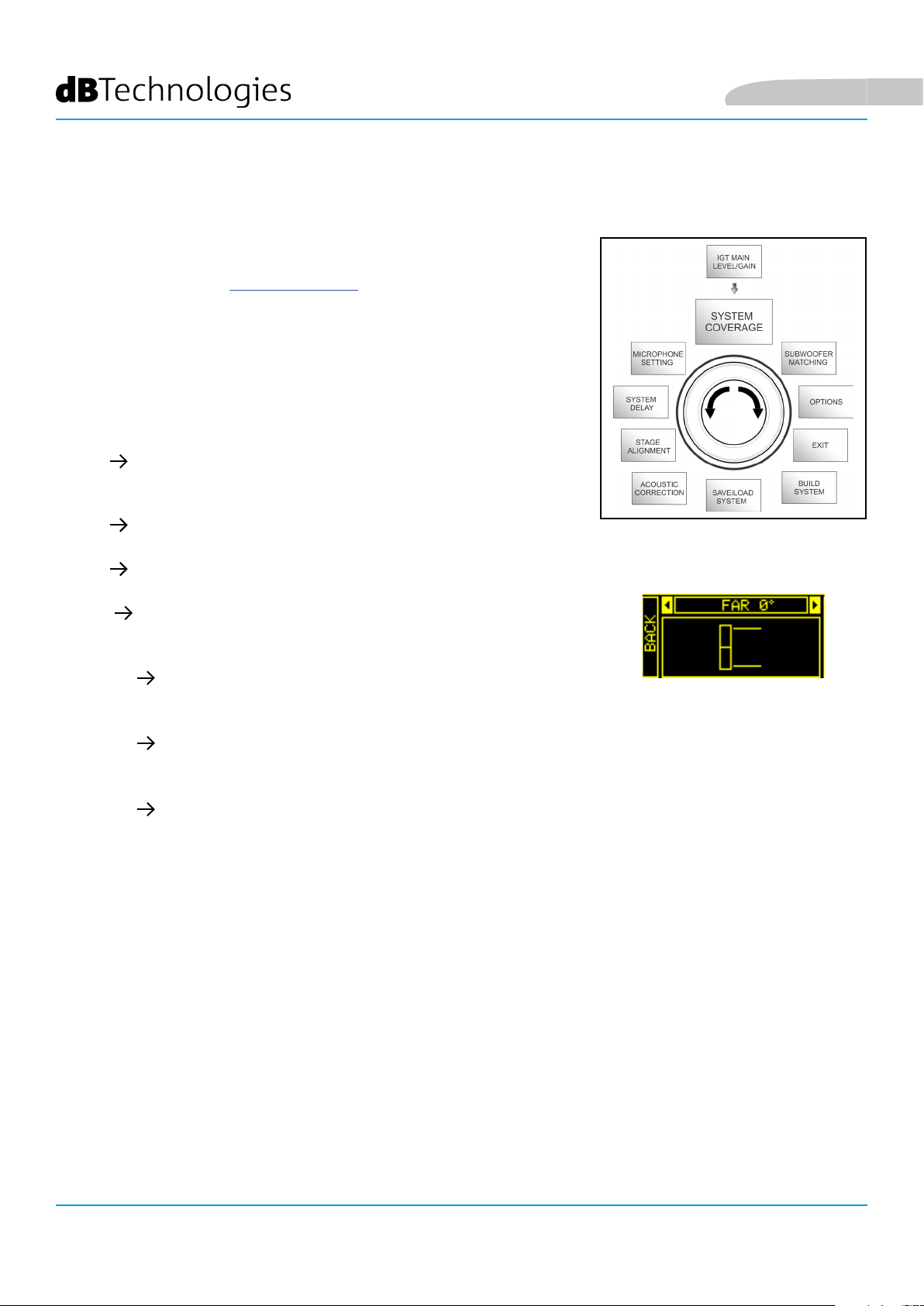
SYSTEM COVERAGE MENU
For information about the functions contained in this menu, only displayed
if during SYSTEM CHECK the system has automatically detected 2 speakers,
also refer to paragraph “DIGITAL STEERING” in the “INSTALLATION
EXAMPLES” section. This menu allows to change the emitted wave beam
and the relevant acoustic coverage, once the DSP has recognized the
installation of 2 IG2T speakers:
• UP +10° for an installation requiring an acoustic coverage from
the bottom up, with mounting on stand or subwoofer and with as
much inclination as possible.
• UP +5° to orientate the wavefront with a medium upward
inclination, with mounting on stand or subwoofer
• UP +2.5° to get an acoustic coverage with a slight upward
inclination.
• FAR 0° when you want a coverage getting as far as possible,
when speakers are installed in front of the auditorium, at the height
of the audience.
• DOWN -2.5° to be used to orientate the acoustic coverage
slightly downward (for example with the public not very far from the
speakers and own installation).
• DOWN -5° for a directivity with a medium downward inclination
(for example with public close to the speakers and own
installation).
• DOWN -10° to incline the acoustic coverage as downward as
possible (public very close to the speakers and own installation).
English
System Coverage Menu
INGENIA IG2T Cod. 420120238 REV. 1.1
60
Page 61

English
SUBWOOFER MATCHING MENU
This menu is only displayed if the presence of at least one subwoofer has
previously been selected, in the BUILD SYSTEM SYSTEM STRUCTURE submenu. In addition, in this case, this menu is accessed automatically after
the “SYSTEM TYPE” settings have been performed, to complete the general
system settings. First of all, the menu allows to identify the subwoofer
in use, then to decide whether to use its crossover frequency or to set
a frequency depending on the model (maximum range 70-120 Hz with a
resolution of 5 Hz). This choice depends on the type of subwoofer-speaker
connection, as shown in the gure below. The menu also suggests the delay
to be set in the subwoofer. To select crossover frequency, after entering the
SUBWOOFER MATCHING menu:
1. Select and conrm the type of associated subwoofer in the system
2. Select and conrm HpFilter, then select and conrm the desired
crossover frequency
3. According to the system settings, verify the delay value recommended
for the subwoofer in the SubDelay eld
4. Select “BACK” or “HOME” to respectively return to the menu selection or
to the main screen
Subwoofer Matching Menu
DIRECT LINK
If necessary, you can directly set a value of HpFilter on IG2T, without using the crossover of a
subwoofer. If instead you use the latter:
a) in the case of DIRECT CONNECTION, check the subwoofer crossover frequency, and replicate it on
IG2T by setting its value in the HpFilter eld.
b) In case of connection XOVER FROM THE SUBWOOFER, set “SubXover” in the eld HpFilter of IG2T.
XOVER FROM SUBWOOFER
INGENIA IG2T Cod. 420120238 REV. 1.1
61
Page 62

OPTIONS MENU
English
PASSWORD
1. ON/OFF (select and conrm whether you
wish to enable/disable the password-protection
of settings).
2. PASSWORD (by selecting and conrming this
item you can specify an alphanumeric password,
consisting of up to 6 digits/characters).
If you forget the password, use the code: Q2R5D9
(ON/OFF and code selection)
SUPERUSER PASSWORD
to unlock the system.
Options Menu
CONTRAST
1. Select and conrm to adjust the OLED display contrast, with an increase in brightness
ranging between 0 and 100% and a resolution of 5%.
STAND-BY
1. ON/OFF (select and conrm whether you wish to enable/disable the timed stand-by of
the control panel).
2. PASSWORD (by selecting and conrming this item you can specify a time period after
which the control panels switches to stand-by mode, ranging between 0’:10’’ – 10’:00 and
with a resolution of 10’’).
(Enabling/disabling of automatic power-off and choice of the time period)
RESTORE
1. Select and conrm to restore the factory settings.
INFO
1. Select and conrm to display the information about the latest rmware version loaded into
the system.
EXIT
1. Select and conrm to exit the OPTIONS menu.
INGENIA IG2T Cod. 420120238 REV. 1.1
62
Page 63

English
EXIT MENU
When selected and conrmed, this menu allows to return to the initial
screen of IG2T.
Exit Menu
INGENIA IG2T Cod. 420120238 REV. 1.1
63
Page 64

4. INSTALLATION EXAMPLES
• To use 2 stacked speakers, you need the optional LP-IG accessory. For further information,
please refer to the instructions of this accessory.
• Always check that the handles, allowing the infra-red communication, are not obstructed;
never cover them and remove any dust or dirt deposits.
• No installation other than that shown here is allowed.
INSTALLATION ON STAND
1 INGENIA IG2T can be installed on an optional standard tripod stand, with a pole
having a diameter of 35 mm. The maximum permissible height between the base
of the speaker and the oor is 150 cm.
ATTENTION!
• Use an appropriately sized stand with the central foot forward to
ensure proper stability.
• When “Stacked” on a stand, the INGENIA IG2T cannot be
mounted in the conguration with 2 speakers stacked, but only
in a single speaker conguration, for safety reasons.
English
INSTALLATION ON SUBWOOFER
Using the GSA-IG accessory during the installation, you can use the speakers (1 o
2) mounted on subwoofer. This allows to get an extremely compact system, with
great output power over the whole range of sound frequencies, installed on the
ground. Additional mechanical xing, or xing with straps, is required to properly
secure the installation. Once the installation is completed, follow the subwoofer
conguration instructions in the SUBWOOFER MATCHING section.
INSTALLATION ON SUBWOOFER WITH POLE
It is possible to use a single speaker mounted on 35 mm diameter pole. Additional
mechanical xing, or xing with straps, is required to properly secure the
installation. The maximum permissible height between the base of the speaker
and the oor is 150 cm. Once the installation is completed, follow the subwoofer
conguration instructions in the SUBWOOFER MATCHING section.
INGENIA IG2T Cod. 420120238 REV. 1.1
64
Page 65

English
FLOOR INSTALLATION
It is possible a oor installation of 1 or 2 INGENIA IG2T using the accessory GSA-IG.
A mechanical xing with screws or screw anchors suited to the type of ooring is
required.
FLOWN INSTALLATION
Flown conguration provides for the hanging of 1 or 2 IG2T speakers, where the
optional accessory DRK-IG allows the use of a shackle, and the combination of
DRK-IG with the optional truss adapter TA-IG allows xing on a specic device,
such as a rig. When the speakers are in a own conguration, it is very advisable to
use both power supply and signal linking, to reduce the complexity of connections,
as shown in the “FIRST SWITCH-ON” section.
ATTENTION!
• When used outdoors, anchor the speaker to prevent any
oscillations due to atmospheric agents and wind.
• Never use the handles to suspend the speaker!
INSTALLATION WITH WALL BRACKETS
INGENIA IG2T can be installed on a wall using the optional brackets WB-IG2. Select
the position so as to obtain optimal coverage. In the case of properly installed dual
vertical speaker (it is mandatory in this case to use LP-IG), consider the possibility
of using digital steering technology (see paragraph). For details, refer to the
instructions of WB-2
INGENIA IG2T Cod. 420120238 REV. 1.1
65
Page 66

DIGITAL STEERING
Digital steering is a technology that can be suitably adopted
to orientate the acoustic coverage of two stacked speakers,
modifying it according to the usage context and installation.
The DSP of INGENIA IG2T may operate on each individual
transducer (whether compression driver or woofer), with
differentiated signal output delays. This way the acoustic
wavefront of 2 stacked speakers can be regarded as equivalent
to that of a single angled speaker, as shown in the gure. In
the setup stage, when it automatically detects the presence
of 2 speakers through the infra-red ports installed on the
handles, IG2T allows to modify the acoustic coverage through
a specic menu, SYSTEM COVERAGE (not displayed if the
speaker is in a single conguration):
English
Hall
For any further information please refer to the section
SYSTEM COVERAGE MENU.
Inclination
INGENIA IG2T Cod. 420120238 REV. 1.1
66
Page 67

English
5. UPDATING THE FIRMWARE
It is very important that you keep the product rmware always up-to-date, to ensure its full functionality.
Periodically check the Web site http://www.dbtechnologies.com, in the “DOWNLOADS” section. Once you verify
that a new rmware version is available:
1. Download the USB BURNER MANAGER in the “SOFTWARE & CONTROLLER” section, then install it following
the relevant instructions
2. Download the .zip le of the latest rmware in the “DOWNLOADS” section for INGENIA IG2T
3. In the top right section of the USB BURNER MANAGER screen, select “File Opening”
4. Select the previously downloaded rmware le (verifying that it is appropriate for your operating system)
5. Click UPDATE
ATTENTION!
When the rmware is updated the presence of the old saved settings
at the next switch-on is not guaranteed.
INGENIA IG2T Cod. 420120238 REV. 1.1
67
Page 68

6. TROUBLESHOOTING
The speaker doesn’t turn on:
1. Check that the power supply upstream of the system is working properly.
2. Verify that the power cord equipped with Neutrik® powerCON TRUE1® connector is properly plugged.
The speaker turns on but it doesn’t output any sound:
1. Verify that the audio signal input connections have been performed properly, using cables equipped
with Neutrik® connectors.
2. Check that the cables in use are not damaged.
3. Check that the mixer or the audio source are on and that they clearly indicate the presence of an output
signal.
4. Verify that the gain level in the initial screen is set to an appropriate value.
English
The speaker is connected, but the control panel is off, including the OLED screen:
1. Turn the push rotary encoder to exit any previously activated display standby.
2. Verify that the power cord equipped with Neutrik® powerCON TRUE1® connectors is properly plugged.
3. Check that the power supply upstream of the system is not cut off.
The speaker outputs a distorted sound:
1. Adjust the source volume rst, then set the IG2T input gain to an appropriate value.
2. Check that the cables in use are not damaged; should that be the case, replace them (a damaged cable
may result in a signal loss or alteration).
3. Verify the menu settings affecting the frequency content of the output signal and in particular:
a) ACOUSTIC CORRECTION
b) MICROPHONE SETTING if a microphone is connected to the input
The system doesn’t detect 2 stacked speakers, and only 1 speaker is displayed in the SYSTEM STRUCTURE screen:
1. Verify that you properly mounted the 2 speakers, stacked, with the upper one ipped, and that you used
and properly fastened the LP-IG connecting brackets as described in the instructions of this accessory.
2. Verify that the upper and lower handles of the speakers, containing the infra-red communication ports,
are not covered in any way.
3. Repeat the “Selfcheck System” procedure in SYSTEM CHECK, as described in the relevant paragraph.
The settings of the different menus in the control panel cannot be modied, though the speaker is clearly on:
1. Verify if any lock password has previously been set.
2. Verify that the push rotary encoder operates properly when rotated and pressed.
INGENIA IG2T Cod. 420120238 REV. 1.1
68
Page 69

English
There is a delay in the sound output of the speaker, with respect to that of the source:
1. Verify the menu settings affecting the delay of the audio signal and in particular:
a) STAGE ALIGNMENT
b) SYSTEM DELAY
The display doesn’t clearly show the menu settings:
1. Access the menu allowing to adjust the display brightness, OPTIONS CONTRAST (see the relevant
information in the OPTIONS MENU paragraph).
INGENIA IG2T Cod. 420120238 REV. 1.1
69
Page 70

7. TECHNICAL SPECIFICATIONS
GENERAL
English
Type:
ACOUSTIC DATA
Frequency Response [-10dB]:
Frequency Response [-6dB]:
Max SPL:
HF compression driver (exit):
HF Voice Coil:
HF Type:
Directivity:
Crossover Frequency:
Vertical 2-way speaker
59 - 20.000 Hz
63 – 19200 Hz
128 dB
1”
1.4” (Titanium)
Neodymium compression driver
Vertical asymmetric
1900 Hz
Coverage (HxV):
LF:
LF Voice coil:
LF Type:
100° x 80° (+15°/-65°)
2 x 8”
2”
Neodymium
AMPLIFIER
Type:
Amplication class:
INGENIA IG2T Cod. 420120238 REV. 1.1
70
Digipro® G3
D class
Page 71

English
RMS amplication power:
Peak power:
Interface:
Automatic rotation display:
Position detection:
Mirroring control (for 2 speakers with
IR control):
Inrush current: 18,64 A
Push rotary encoder + OLED display
400 W
800 W
Yes
EPD
Yes
PROCESSOR
Internal controller:
A/D D/A Converter:
DSP 56 bit
24 bit/48 kHz
Settings:
Limiter:
INPUTS
Inputs:
Outputs:
USB:
DIMENSIONS
Material:
Grid:
Factory settings and customisable settings that can be saved and recalled
Peak, RMS, Thermal
1x Combo (XLR/Jack) balanced/unbalanced
1x XLR link OUT
Mini US, B type
Reinforced PP Polypropylene
Painted steel / CNC machining
Yes
Ready for y-bar:
INGENIA IG2T Cod. 420120238 REV. 1.1
71
Page 72

English
Handles:
Installation on pole:
Width:
Height:
Depth:
Weight:
1 upper / 1 lower with IR interface
Yes, 36 mm
228 mm (8.98 in)
646 mm (25.43 in)
315 mm (12.40 in)
12.8 kg (28.22 lbs)
INGENIA IG2T Cod. 420120238 REV. 1.1
72
Page 73

English
Features, specication and appearance of products are subject to change without notice.
dBTechnologies reserves the right to make changes or improvements in design or manufacturing without
assuming any obligation to change or improve products previously manufactured.
A.E.B. Industriale Srl
Via Brodolini, 8
Località Crespellano
40053 VALSAMOGGIA
BOLOGNA (ITALIA)
Tel +39 051 969870
Fax +39 051 969725
www.dbtechnologies.com
info@dbtechnologies-aeb.com
INGENIA IG2T Cod. 420120238 REV. 1.1
73
Page 74

Deutsch
INHALTSVERZEICHNIS
1. ALLGEMEINE INFORMATIONEN ...........................................................................................76
WILLKOMMEN! ..................................................................................................................76
EINFÜHRENDE ÜBERSICHT.................................................................................................76
HINWEISE FÜR DEN BENUTZER .........................................................................................76
MECHANISCHE UND AKUSTISCHE MERKMALE ................................................................77
ABMESSUNGEN .......................................................................................................................................... 77
AKUSTISCHES BESCHALLUNGSFELD ......................................................................................................... 77
ZUBEHÖR ................................................................................................................................................... 78
MERKMALE DER VERSTÄRKER- UND STEUERSEKTION ....................................................79
INPUT AND CONTROL SECTION ................................................................................................................ 80
NETZTEIL .................................................................................................................................................... 81
2. ERSTE INBETRIEBNAHME .....................................................................................................82
VERPACKUNGSINHALT .......................................................................................................82
INSTALLATION .....................................................................................................................82
ANSCHLUSS DER EINGÄNGE ..................................................................................................................... 82
ANSCHLUSS DER STROMVERSORGUNG ................................................................................................... 83
ANSCHLUSS DER AUSGÄNGE UNTER MEHREREN MODULEN (Durchschleifen der Stromversorgung) 84
ANSCHLUSS DER AUSGÄNGE UNTER MEHREREN MODULEN (Durchschleifen des Audiosignals) ....... 85
VERWENDUNG VON ZWEI ÜBERLAGERTEN LAUTSPRECHERN IG2T .................................................... 86
3. BEDIENTAFEL UND EINSTELLUNGS-MENÜ .........................................................................87
AUFRUF DES MENÜS ..........................................................................................................87
MENÜ BUILD SYSTEM ........................................................................................................90
SYSTEM CHECK .......................................................................................................................................... 90
SYSTEM STRUCTURE .................................................................................................................................. 90
SYSTEM TYPE ............................................................................................................................................. 91
MENÜ SAVE/LOAD SYSTEM ...............................................................................................91
MENÜ ACOUSTIC CORRECTION .........................................................................................92
MENÜ STAGE ALIGNMENT .................................................................................................93
MENÜ SYSTEM DELAY ........................................................................................................93
MENÜ MICROPHONE SETTING ..........................................................................................94
MENÜ SYSTEM COVERAGE ................................................................................................95
MENÜ SUBWOOFER MATCHING .......................................................................................96
MENÜ OPTIONS ..................................................................................................................97
PASSWORD ................................................................................................................................................ 97
CONTRAST .................................................................................................................................................. 97
STAND-BY ................................................................................................................................................... 97
RESTORE ..................................................................................................................................................... 97
INFO ........................................................................................................................................................... 97
EXIT............................................................................................................................................................. 97
MENÜ EXIT ..........................................................................................................................98
INGENIA IG2T Cod. 420120238 REV. 1.1
74
Page 75

Deutsch
INHALTSVERZEICHNIS
4. INSTALLATIONSBEISPIELE .....................................................................................................99
INSTALLATION AUF STATIV .................................................................................................99
INSTALLATION AUF SUBWOOFER ......................................................................................99
INSTALLATION AUF SUBWOOFER MIT STÄNDER ..............................................................99
BODENINSTALLATION ......................................................................................................100
HÄNGE- INSTALLATION ....................................................................................................100
WANDINSTALLATION MIT BÜGELN .................................................................................100
DIGITAL STEERING ............................................................................................................101
5. AKTUALISIERUNG DER FIRMWARE ...................................................................................102
6. TROUBLESHOOTING ............................................................................................................103
7. TECHNISCHE DATEN ............................................................................................................105
ALLGEMEINES .......................................................................................................................................... 105
AKUSTISCHE DATEN ................................................................................................................................. 105
VERSTÄRKER ........................................................................................................................................... 105
PROZESSOR .............................................................................................................................................. 106
EINGÄNGE ................................................................................................................................................ 106
ABMESSUNGEN ........................................................................................................................................ 106
INGENIA IG2T Cod. 420120238 REV. 1.1
75
Page 76

Deutsch
1. ALLGEMEINE INFORMATIONEN
WILLKOMMEN!
Dank für den Erwerb eines in Italien von dBTechnologies geplanten und entwickelten Produkts! Dieser aktive,
vertikale 2-Wege-Lautsprecher birgt in sich jahrelange Erfahrung auf dem Gebiet Tonwiedergabe unter
Anwendung innovativer Lösungen auf dem Gebiet der Akustik, der Elektronik und Materialforschung.
EINFÜHRENDE ÜBERSICHT
Der aktive Lautsprecher INGENIA IG2T ist ein aktiver, vertikaler 2-Wege- Lautsprecher mit 2 St. 8”- Woofern und
1 St. 1” (Ausgang)- Kompressionstreiber (Schwingspule: 1.4”), gesteuert durch einen Verstärker DIGIPRO G3
neuester Generation mit 400 W RMS Leistung. Unter den innovativsten Merkmalen sind zu nennen:
• eine sorgfältige Auslegung der Trompete mit asymmetrischer Richtung, spezisch entwickelt zur
Gewährleistung eines optimalen Beschallungsfelds zur sicheren Erzielung einer kompromisslosen
Klangqualität in unterschiedlichen Anwendungsbereichen in Innenräumen und im Freien.
• Digital steering, gesteuert durch den leistungsstarken eingebauten DSP-Prozessor bei Verwendung von
2 überlagerten Lautsprechern, so dass ein größeres Beschallungsfeld und höhere Klangleistung bei
kompromissloser Genauigkeit und Klarheit erzielt werden.
• Automatisches Erkennen der Konguration mit 2 Lautsprechern dank der Infrarot- Kommunikation an
den Griffen (EPD-Technologie) und der schnellen, personalisierbaren Steuerung mittels DSP. In dieser
Konguration richten sich die OLED- Displays automatisch aus. Es müssen nur die Bedienelemente
eines der beiden Lautsprecher bedient werden, um das gesamte System anzusteuern.
• Innovatives Shape mit 2 Woofern und 1 Driver in einem Gehäuse, das Robustheit mit Klangleistung,
Kompaktheit und Handlichkeit verbindet.
• Äußerste Vielseitigkeit, die es gestattet, die persönlichen Einstellungen schnell und unmittelbar zu
speichern und alle Einstellungen durch die Eingabe eines Passworts zu schützen.
HINWEISE FÜR DEN BENUTZER
Um Ihren INGENIA IG2T auf bestmögliche Weise verwenden zu können, empfehlen wir:
• Die in der Verpackung enthaltene Quickstart- Betriebsanleitung und diese vollständige
Betriebsanleitung ausführlich zu lesen und während der gesamten Standzeit des Produkts zu
verwahren
• Das Produkt anzumelden auf der Website http://www.dbtechnologies.com in der Sektion “SUPPORT”
• Die aktuellste Version der Firmware herunterzuladen und zu installieren von der Website http://www.
dbtechnologies.com in der Sektion “FIRMWARE” (siehe Kapitel AKTUALISIERUNG DER FIRMWARE)
• Den Kaufbeleg aufzubewahren und der GARANTIE (BEDIENUNGSANLEITUNG - Abschnitt 2)
INGENIA IG2T Cod. 420120238 REV. 1.1
76
Page 77

Deutsch
MECHANISCHE UND AKUSTISCHE MERKMALE
ABMESSUNGEN
INGENIA IG2T enthält in einem verstärkten Polypropylengehäuse
mit 12.8 kg Gewicht zwei 8”-Woofer und einen 1” (Ausgang)Kompressionstreiber (Schwingspule: 1.4”) mit Neodym-
Magneten hervorragender Eigenschaften in Bezug auf
Kompaktheit, Gewicht und Leistung. Die interne, leichte
Metallstruktur verbessert die Steigkeit und das akustische
Verhalten. Die Abmessungen eines einzelnen Lautsprechers
sind: 228 x 646 x 315 mm. Die Griffe gestatten leichten Transport
und Verlagerung des Lautsprechers auch durch eine einzelne
Person. Darüber hinaus sind verschiedene Kongurationen
möglich, von der Installation auf Subwoofer bis zur hängenden
Installation des einzelnen oder doppelten Lautsprechers.
AKUSTISCHES BESCHALLUNGSFELD
Die besondere Öffnungsweite der Trompete, die in der
Abbildung schematisch dargestellt ist, gewährleistet ein
Gesamt- Beschallungsfeld von 100 x 80° (+15°/- 65°). Dieses
asymmetrische, vertikale Richtverhalten gewährleistet
ausgezeichnete Beschallung sowohl in Innenräumen als
auch im Freien. Bei überlagerter Installation von 2 IG2T
kann darüber hinaus mit dem Digital Steering der Gesamt-
Beschallungsbereich der Lautsprecher gesteuert werden,
so dass trotz vertikaler Installation der IG2T die gleiche
Wirkung erzielt wird, wie bei einem einzelnen, schräg geneigt
montierten Lautsprecher, was höchste Vorteile in Bezug auf
das Richtverhalten hat.
INGENIA IG2T Cod. 420120238 REV. 1.1
77
Page 78

ZUBEHÖR
Für eine rasche Montage sind als Option die folgenden Zubehörteile verfügbar:
• Fly-bar DRK-IG (und optionaler TA-IG) für vertikale Aufhängung
• Paar Befestigungsbügel LP-IG für die Befestigung von 2 übereinander gestapelten Modulen IG2T .
• Optionaler Ständer GSA-IG für die Montage auf Subwoofer (oder für die Montage an dem Boden).
• Wandbügel WB-IG2 für feste Wandinstallation.
• Für den Transport und den Schutz des Lautsprechers stehen eine spezielle Tasche TC-IG2T und eine
Regenschutzabdeckung zur Verfügung RC-M1.
Deutsch
Fly Bar DRK-IG LP-IG
TA-IG truss adapter
Ständer GSA-IG
ACHTUNG!
• Zum Aufhängen des Lautsprechers keinesfalls
die Griffe verwenden!
Für weitere Informationen wenden Sie sich bitte an die zuständigen Handbüchern.
WB-IG2
INGENIA IG2T Cod. 420120238 REV. 1.1
78
Page 79

Deutsch
MERKMALE DER VERSTÄRKER- UND STEUERSEKTION
Der Digitalverstärker neuester Generation DIGIPRO G3 der
Klasse D bildet den Kern des IG2T und liefert eine Klangleistung
von 400 W RMS.
Dank des Switching- Netzgeräts mit besonders wirksamer AutoRange-Funktion ist das Gerät geräuscharm und benötigt keinen
aktiven Kühlapparat.
Die Steuerung des Systems erfolgt durch einen spezischen DSPProzessor, der das Einstellen verschiedener Parameter gestattet,
sowie die automatische Steuerung der Kommunikation
zwischen den Modulen bei Kongurationen mit 2 überlagerten
Lautsprechern. In diesem letzteren Fall steuert der DSP einzeln
die akustischen Komponenten, um eine kongurierbare
Richtwirkung zu erzielen (Digital Steering).
STEUERSEKTION
EINGANGS- UND
ACHTUNG!
• Das Modul muss vor Feuchtigkeit geschützt
werden
• Es darf keinesfalls versucht werden, den
Verstärker zu öffnen
• Bei Funktionsstörungen sofort die
Stromversorgung unterbrechen, indem
der Netzstecker des Moduls abgezogen
wird. Dann Kontakt mit einer autorisierten
Reparaturwerkstatt aufnehmen
Das Bedienfeld des DIGIPRO G3 ist charakterisiert durch:
• EINGANGS- UND STEUERSEKTION
• VERSTÄRKER
• NETZTEIL
VERSTÄRKER
NETZEIL
INGENIA IG2T Cod. 420120238 REV. 1.1
79
Page 80

Deutsch
INPUT AND CONTROL SECTION
1. LED “PEAK”
Die rote Led leuchtet im Moment des Anschlusses der
Stromversorgung kurz auf, bzw. wenn der Audio-Limiter in
Betrieb ist.
ACHTUNG!
Den Lautsprecher nicht längere Zeit
bei eingeschalteter oder blinkender
Led betreiben, die einen Betrieb
unter übermäßig hoher Belastung bei
Verzerrungen anzeigt.
2. DISPLAY OLED
Das Display richtet sich automatisch aufgrund der
Beschleunigungs-Überwachung aus, die erkennt, ob der Lautsprecher
aufrecht oder kopfüber installiert wurde. Es besteht die Möglichkeit, eine Kontrastregelfunktion und eine
Selbstabschaltungs-Funktion zu kongurieren (siehe Kap. BEDIENTAFEL UND EINSTELLUNGS-MENÜ).
3. PUSH ROTARY ENCODER
Der Push Rotary Encoder gestattet die Auswahl sowohl durch Drehen (Auswahl Menü und Einstellwerte), als auch
durch Druck (Bestätigung der vorgenommenen Auswahl) für die Navigation im Menü.
4. USB SERVICE DATA
Anhand des Mini USB-Ports Typ B kann die Firmware des Geräts upgedatet werden. Weitere Informationen
stehen zur Verfügung auf der Website http://www.dbtechnologies.com in der Sektion “FIRMWARE” und Kapitel
AKTUALISIERUNG DER FIRMWARE).
ACHTUNG!
Der Anschluss USB SERVICE DATA darf ausschließlich zum Updaten der
Firmware des Produkts verwendet werden. Keine USB-Einheiten am
Gerät anschließen, da andernfalls Schäden oder Funktionsstörungen
auftreten können.
5. AUSGANG “LINK”
Symmetrischer Ausgang XLR, der es gestattet, das Audio-Signal an einen weiteren Lautsprecher mit Verstärker zu
senden.
6. EINGANG “INPUT” COMBI
Kombinierter Eingang XLR-TR-TRS des Audio-Signals. Gestattet die Verwendung eines symmetrischen Steckers XLR
oder einer Steckbuchse TS oder TRS zu ¼”.
ACHTUNG!
Ausschließlich Kabel mit hochwertigen Originalsteckern Neutrik®
verwenden. Die Verwendung anderer oder qualitativ minderwertiger
Stecker könnte die Funktionstüchtigkeit des Lautsprechers
beeinträchtigen.
7. WAHLSCHALTER “INPUT SENSITIVITY”
Dieser Wahlschalter dient zur Unterscheidung zwischen einem vom Mixer oder der Leitung kommenden (“LINE”)
und einem vom Mikrofon kommenden Signal (“MIC”).
INGENIA IG2T Cod. 420120238 REV. 1.1
80
Page 81

Deutsch
NETZTEIL
8. VERSORGUNGSEINGANG “AUTO-RANGE MAINS INPUT”
Eingang für Stecker Neutrik® powerCON TRUE1.
9. AUSGANG ZUM DURCHSCHLEIFEN DER VERSORGUNGSSPANNUNG “MAINS LINK”
Dank der Verbindung mit Stecker Neutrik® NAC3PX besteht die Möglichkeit, die Spannungsversorgung
zu einem zweiten Modul durchzuschleifen.
10. SCHMELZSICHERUNG “MAINS FUSE”
Netzsicherung
ACHTUNG!
Der Lautsprecher wird mit bereits eingesetzter Sicherung für den Betrieb mit
220-240 V ausgeliefert.
Wenn das Gerät mit 100-120 V Spannung versorgt werden soll:
1. Alle Anschlüsse lösen, einschließlich der Stromversorgung
2. 5 Minuten abwarten
3. Die Sicherung durch die mitgelieferte Sicherung für Spannungsbereich 100-120V ersetzen
4. Ausschließlich das mitgelieferte V ersorgungskabel verwenden.
INGENIA IG2T Cod. 420120238 REV. 1.1
81
Page 82

Deutsch
2. ERSTE INBETRIEBNAHME
VERPACKUNGSINHALT
Bitte kontrollieren, dass der Inhalt der Verpackung des Lautsprechers INGENIA IG2T vollständig vorhanden ist:
• Versorgungskabel mit Stecker Neutrik® powerCON TRUE1®
• INGENIA IG2T
• Quick-Start-Anleitung und Garantie-Unterlagen
• Schmelzsicherung für Betrieb mit 100-120V Spannung
ACHTUNG!
Der Lautsprecher wird mit bereits eingesetzter Sicherung für den Betrieb
mit 220-240 V ausgeliefert. Wenn das Gerät mit 100-120 V Spannung versorgt
werden soll:
1. Alle Anschlüsse lösen, einschließlich der Stromversorgung
2. 5 Minuten abwarten
3. Die Sicherung durch die mitgelieferte Sicherung für Spannungsbereich 100-120V ersetzen
4. Ausschließlich das mitgelieferte Versorgungskabel verwenden.
INSTALLATION
ANSCHLUSS DER EINGÄNGE
MIXER / LINE MIKROPHON
INGENIA IG2T Cod. 420120238 REV. 1.1
82
Page 83

Deutsch
ANSCHLUSS DER STROMVERSORGUNG
STROMVERSORGUNG
ACHTUNG!
Ausschließlich Kabel mit Stecker Neutrik® verwenden
Eventuell beschädigte Kabel müssen ersetzt werden, um Funktionsstörungen
und schlechte Tonqualität zu vermeiden.
Zur korrekten Installation des Lautsprechers INGENIA IG2T ist wie folgt vorzugehen:
• Den Audio-Eingang korrekt anschließen und die Tonquelle anhand des Wahlschalters “Input
sensitivity” (6) einstellen. Bei Eingang eines Leitungssignals oder eines Signals vom Ausgang eines
Mixers, den Wahlschalter (7) auf “LINE” stellen, bei Eingang von einem Mikrofon (dynamisches
Mikrofon verwenden), den Wahlschalter (7) auf “MIC” stellen. Eine rasche Übersicht über die Audio-
Kabel bietet die Tabelle auf Seite 82.
• Die Stromversorgung anschließen, indem das Kabel mit Stecker Neutrik® Typ powerCON TRUE1® in den
Anschluss “MAINS INPUT” (8) eingesteckt wird.
• Beim Einschalten blinkt die Schaltspitzen-Led kurz und das Display OLED (2) wird aktiviert und zeigt
den Anfangsbildschirm zur Kontrolle des Pegels und des Gains an:
• Den Schalter PUSH ROTARY ENCODER (3) nach links oder rechts drehen, um den Gain des Systems auf
einen ausreichenden Pegel einzustellen.
• Die korrekte Tonabgabe des IG2T kontrollieren.
INGENIA IG2T Cod. 420120238 REV. 1.1
83
Page 84

ANSCHLUSS DER AUSGÄNGE UNTER MEHREREN MODULEN
(Durchschleifen der Stromversorgung)
Deutsch
HINWEIS FÜR DEN INSTALLATEUR (100-120V). Die Angaben auf dem Schild am Paneel des Diffusors
beziehen (und beschränken) sich auf fas mitgelieferte Kabel. Falls dieses Kabel nicht verwendet
wird, gelten als Höchstwerte für Strom (und Leistung) von LINK die in der folgenden Tabelle
angegebenen Werte:
Modell Strom (100-120 V) Leistung (100-120 V)
IG2T (100-120 V) 18 A 1900 W
Die Kabel müssen angemessen dimensioniert sein und die Planung, Installation und Überprüfung
der Anlage darf nur durch qualiziertes Personal ausgeführt werden. A.E.B. Industriale übernimmt
keine Haftung bei Verwendung von nicht angemessenen, zertizierten oder mit der Auslegung
der Anlage, sowie den jeweiligen geltenden nationalen Bestimmungen kompatiblen Kabel.
STROMVERSORGUNG LINK
INGENIA IG2T Cod. 420120238 REV. 1.1
84
Page 85

Deutsch
Durch die Verwendung der Anschlüsse Neutrik® PowerCon TRUE1® mit IG2T kann die Speisung bis zu einem
maximalen Strom von 15 A (3400 W) in Ländern mit einer Versorgungsspannung von 220-240Vac und 14 A (1600
W) in Ländern mit einer Versorgungsspannung von 100-120Vac vom ersten Diffusor zum nächsten weitergeführt
werden. Für diesen Verbindungsstyp ist es ausreichend, das beiliegende Speiserkabel mit dem Eingang MAINS
INPUT (8) des ersten IG2T und das Kabel LINK POWERCON TRUE1® (optional) zwischen dem Ausgang MAIN LINK
(9) und dem Eingang MAINS INPUT (8) des nächsten IG2T anzuschließen. Dieser Verbindungsstyp kann wiederholt
werden, bis der zulässige und vom MAINS LINK (9) des ersten Diffusors angezeigte maximale Strom erreicht wird.
ACHTUNG!
Der auf dem Schild des IG2T (MAIN LINK) angegebene Wert des zulässigen maximalen Stroms wird
mit der Angabe des maximalen Stroms des Anschlusses PowerCON TRUE1 berechnet; dieser Wert ist
nicht absolut, sondern abhängig von dem Kabeltyp, der für den Anschluss des ersten IG2T an das Netz
verwendet wird (verwendeter Querschnitt und Steckertyp), sowie von den darauffolgenden LINKKabeln (verwendeter Querschnitt und Steckertyp). Während der Planungs- und Auslegungsphase der
Anlage und vor den Serienanschlüssen der Produkte immer die zulässigen maximalen Ströme (und
Leistungen) sowie die genaue Dimensionierung der Querschnitte der verwendeten Kabelleitungen
überprüfen.
ANSCHLUSS DER AUSGÄNGE UNTER MEHREREN MODULEN
(Durchschleifen des Audiosignals)
INPUT
Zum Anschluss von 2 oder mehr Lautsprechern an der gleichen Tonquelle kann es bei verschiedenen
Installationsarten hilfreich sein, das Signal von einem ersten auf einen zweiten Lautsprecher u.s.f.
durchzuschleifen. Zunächst eine beliebige Tonquelle an den Eingang “INPUT” (6) des ersten Lautsprechers
anschließen (bezüglich des unterschiedlichen Anschlusses von “LINE” oder “MIC” siehe Abschnitt ANSCHLUSS
DER EINGÄNGE). Dann mit einem symmetrischen Kabel XLR den Ausgang “LINK” (5) des ersten Lautsprechers
an den Eingang “INPUT” (6) des zweiten anschließen. Dieser zweite Vorgang kann dann zum Anschluss weiterer
Lautsprecher wiederholt werden, bis der für die Umgebung am besten geeignete Aufbau erreicht ist.
INGENIA IG2T Cod. 420120238 REV. 1.1
LINK
85
Page 86
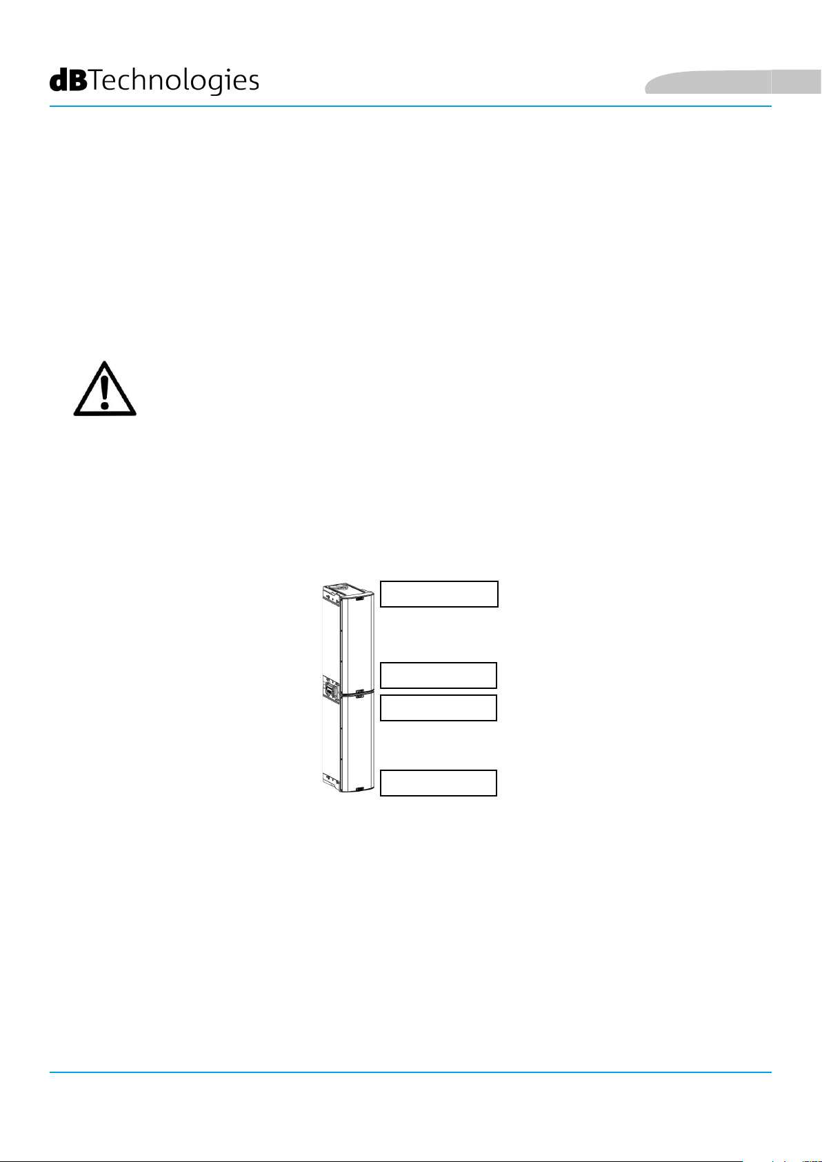
Deutsch
VERWENDUNG VON ZWEI ÜBERLAGERTEN LAUTSPRECHERN IG2T
Zur korrekten Montage und Verwendung von zwei übereinander angeordneten Lautsprechern IG2T ist
ein Verbindungsbügel IP-IG erforderlich Alle weiteren Angaben sind der Anleitung dieses Zubehörteils zu
entnehmen.
Nachdem die beiden Lautsprecher korrekt montiert wurden, ist die Infrarot- Erkennung an den Griffen
automatisch wirksam. Es muss lediglich in den Anfangs- Kongurationsmenüs das Checken vorgenommen
werden, wie im folgenden Kapitel beschrieben.
ACHTUNG!
• Die Infrarot- Ports gestatten Montage, Dialog und Erkennung nur bei 2
identischen Lautsprechern.
• Zum Aufhängen des Lautsprechers keinesfalls die Griffe verwenden!
UNTERSEITE
OBERSEITE
OBERSEITE
UNTERSEITE
INGENIA IG2T Cod. 420120238 REV. 1.1
86
Page 87

Deutsch
3. BEDIENTAFEL UND EINSTELLUNGS-MENÜ
AUFRUF DES MENÜS
Der Push Rotary Encoder (3) gestattet sowohl die Auswahl durch Drehen als auch die Bestätigung durch Drücken.
Diese Auswahl- und Bestätigungsfunktionen gestatten die Navigation in den Menüs und Submenüs, die am OLEDDisplay (2) angezeigt werden. Innerhalb der Menüs und Submenüs gestattet das Drehen des Schalters nach links
oder rechts auch das Erhöhen oder Verringern der angewählten Werte.
SELEKTIEREN / ABNEHMENBESTÄTIGEN
Der Anfangsbildschirm nach dem Einschalten zeigt den Pegel und den Gain des IG2T an. Alle Einstellungen
können durch ein Passwort geschützt werden.
• Nachdem die Einstellungen von Hand vorgenommen wurden, bleiben diese auch
nach dem Abschalten des Lautsprechers gespeichert.
• Wenn ca. eine Minute lang keine Auswahl oder Bestätigung vorgenommen
wird, schaltet das System automatisch wieder auf den Anfangsbildschirm zurück
(IG2T level/gain). Dieser Rücksprung kann zu jeder Zeit auf 2 Arten auch bewusst
vorgenommen werden:
a. Durch Anwahl und Bestätigung des folgenden Symbols, sofern im Submenü vorhanden
b. Durch gedrückt Halten des Push Rotary Encoders für die Dauer von einigen Sekunden
• Wenn 2 Lautsprecher korrekt übereinander montiert wurden, erkennt sie das
System, so dass beide Lautsprecher anhand des Rotary-Schalters eines einzelnen
Lautsprechers gesteuert werden können (mirroring OLED).
Beim Einschalten des IG2T zeigt das Display den Anfangsbildschirm an, der GAIN und Signalpegel durch
Simulieren eines VU METER anzeigt.
SELEKTIEREN / ZUNEHMEN
INGENIA IG2T Cod. 420120238 REV. 1.1
87
Page 88

Deutsch
Durch Drücken des Rotary Push Encoders können in diesem Bildschirm die verschiedenen Menüs aufgerufen
werden, deren generelle Struktur in der Abbildung dargestellt ist.
die Struktur der Menüs
ACHTUNG!
• Das Menü “SYSTEM COVERAGE” wird nur dann angezeigt, wenn das
System auf automatischem Wege anhand der Infrarot- Ports an den
Griffen erkannt hat, dass zwei überlagerte Lautsprecher vorhanden sind.
• Das Menü “SUBWOOFER MATCHING” wird nur dann angezeigt, wenn bei
der Einstellung das Vorhandensein eines Subwoofers angegeben wurde.
INGENIA IG2T Cod. 420120238 REV. 1.1
88
Page 89

Deutsch
Die Struktur der Hauptmenüs kann in Form eines Kreises dargestellt werden, da der Push Rotary Encoder das
Durchblättern durch Drehen sowohl nach links als auch nach rechts gestattet.
Kreisform
INGENIA IG2T Cod. 420120238 REV. 1.1
89
Page 90

MENÜ BUILD SYSTEM
Dieses Menü konguriert das System automatisch
aufgrund der Anzahl Lautsprecher, des Vorhandenseins
oder Fehlens eines Subwoofers, der Lage und Neigung
der Lautsprecher selbst. Es besteht aus 3 Submenüs:
• SYSTEM CHECK
• SYSTEM STRUCTURE
• SYSTEM TYPE
Deutsch
Build System Menü
Sub-menüs
SYSTEM CHECK
Das System ist in der Lage anhand der Infrarot- Kommunikation (die
Kommunikations-Ports benden sich an den Griffen der Lautsprecher und die
Erkennung erfolgt automatisch) festzustellen, ob der Benutzer einen oder zwei
Lautsprecher IG2T verwendet. Nach dem Aufruf dieses Bildschirms:
1. Durch Drehen des Rotary Encoders das Selfcheck System anwählen und die Auswahl durch Drücken des
Rotary Encoders bestätigen.
2. Nach einer kurzen Animation schaltet das System automatisch auf das nächste Menü weiter (SYSTEM
STRUCTURE).
3. Sofern dieser Vorgang nicht benötigt wird, die Position NEXT anwählen und bestätigen. Wenn der
Hauptbildschirm wieder aufgerufen werden soll, muss dagegen BACK angewählt und bestätigt werden.
SYSTEM STRUCTURE
Das Menü gestattet es, von Hand das Vorhandensein eines oder mehrerer Subwoofer
in der verwendeten Konguration einzugeben. Wenn die Zahl der angeschlossenen
Subwoofer berichtigt werden soll:
1. Den Rotary Encoder auf “Subwoofer” einstellen und bestätigen
2. Die Anzahl der zu verwendenden Subwoofer anwählen und bestätigen
3. Zum Weiterschalten auf das nächste Menü, die Position NEXT anwählen und bestätigen. Zum Rücksprung
in das Submenü SYSTEM CHECK ist BACK anzuwählen und zu bestätigen.
INGENIA IG2T Cod. 420120238 REV. 1.1
90
Page 91

Deutsch
SYSTEM TYPE
Die bei Verwendung von IG2T vorgesehenen System-Typen sind 2:
• Stacked
• Flown
In der Konguration “Stacked” können 1 oder 2 Lautsprecher IG2T auf einem Ständer oder auf Subwoofer
aufgestellt werden (siehe Kapitel INSTALLATIONSBEISPIELE). In der Konguration “Flown” werden dagegen ein
oder zwei Lautsprecher IG2T hängend montiert. Nach Aufruf des Menüs SYSTEM TYPE:
• Die gewünschte Modalität “Stacked” oder “Flown” anwählen und bestätigen. Durch Anwahl und Bestätigung
von NEXT wird auf den nächsten Bildschirm weitergeschaltet (durch Anwahl und Bestätigung von BACK
erfolgt das Rückschalten auf den vorherigen Bildschirm). Wenn das System zuvor das Vorhandensein
von 2 Lautsprechern festgestellt hat, wird nun das Menü SYSTEM COVERAGE aufgerufen und wenn das
Vorhandensein eines Woofers im vorherigen Submenü SYSTEM STRUCTURE eingegeben wurde, wird
dann das Menü SUBWOOFER MATCHING angezeigt, andernfalls (Speakers 1, Subwoofer 0) wird wieder
Anfangsbildschirm angezeigt und der Vorgang ist damit beendet.
ACHTUNG!
• Den Lautsprecher keinesfalls direkt auf dem Boden aufstellen. Es
muss immer ein Ständer (nicht mitgeliefert) mit einer Standardstange
Durchmesser 35 mm und ein Stativ mit nach vorn gerichtetem mittlerem
Fuß eingesetzt werden. Stets die effektive Stabilität der Installation
kontrollieren.
• Das Modell INGENIA IG2T in der Anordnung “Stacked” auf Ständer kann
aus Sicherheitsgründen nicht mit 2 überlagerten Lautsprechern montiert
werden, sondern ausschließlich mit einem einzelnen Lautsprecher.
MENÜ SAVE/LOAD SYSTEM
Dieses Menü gestattet das Speichern und das spätere Abrufen der
Einsatz-Kongurationen des Systems. Obgleich im IG2T beim Abschalten
alle vorgenommenen Einstellungen gespeichert bleiben, kann es sehr
sinnvoll sein, für unterschiedliche Umgebungsbedingungen ebenso viele
unterschiedliche Einstellungen zu speichern, um sie bei Bedarf dann rasch
abrufen zu können. Zu diesem Zweck gestattet der IG2T das Speichern
und die Benennung von 5 Einstellungen mit der Funktion “SAVE” und
deren Abruf anhand der Funktion “RECALL”. Wenn eine der gespeicherten
Einstellungen geändert werden muss, können die bereits gespeicherten
Einstellungen überschrieben werden.
Save/Load System Menü
INGENIA IG2T Cod. 420120238 REV. 1.1
91
Page 92

Deutsch
Zum Speichern einer Einstellung, nach Eingabe der verschiedenen Parameter in den anderen Menüs schließlich
das Menü SAVE/LOAD SYSTEM aufrufen und:
1. Die Nummer einer der gespeicherten Einstellungen mit der Nummer 1 bis 5 anwählen und bestätigen
2. Die Funktion “SAVE” anwählen und bestätigen.
3. Der neuen Einstellung einen Titel zuweisen. Der Titel ist alphanumerisch und umfasst 14 Buchstaben/Ziffern.
Neben der Nummer des Speicherplatzes wird ein Buchstabe nach dem anderen eingegeben und bestätigt.
Wenn der Titel beendet ist, lediglich den Unterstreichungsstrich (_) bestätigen (ohne Anwahl).
4. Im nächsten Bildschirm “OK” drücken
5. Das System speichert nun die Einstellungen im angegebenen Speicherplatz mit dem eingegebenen Titel.
Zum Aufruf und Laden einer solchen Einstellung im System:
1. Den gewünschten Speicherplatz anwählen und bestätigen
2. Die Funktion “RECALL” anwählen und bestätigen.
3. Im nächsten Bildschirm “OK” drücken
4. Das System hat nun die Einstellungen aus dem angegebenen Speicherplatz geladen und schaltet auf den
Hauptbildschirm zurück
Zum Überschreiben einer vorhandenen Einstellung den entsprechenden Speicherplatz anwählen und dann im
Bildschirm Overwrite OK anwählen und bestätigen.
MENÜ ACOUSTIC CORRECTION
Es kann bei verschiedenen Gelegenheiten sinnvoll sein, eine
differenzierte Entzerrung des Ausgangssignals des Lautsprechers
vorzunehmen. Der im IG2T eingebaute DSP-Prozessor verwaltet auch
diese Option.
Zu diesem Zweck muss das Menü ACOUSTIC CORRECTION aufgerufen
werden. Dann:
1. Das zu korrigierende Frequenzband anwählen und bestätigen. Es
sind 3 Frequenzbänder möglich:
A. LF - Low Frequency, mit Korrekturspanne + 3dB - 6
dB und Auösung 0.5 dB
B. MF - Medium Frequency, mit Korrekturspanne + 0
dB - 6 dB und Auösung 0.5 dB
C. HF - High Frequency, mit Korrekturspanne + 3 dB - 6
dB und Auösung 0.5 dB
2. Den gewünschten Korrekturbereich anwählen und bestätigen
3. Falls es notwendig ist, den Vorgang auf den anderen Frequenzbändern zu
wiederholen, wieder bei Punkt 1 beginnen, andernfalls das Symbol “Home”
anwählen und wieder zur Hauptmenü- Auswahl zurückkehren.
Acoustic Correction Menü
• Die Funktion Acoustic Correction kann verwendet werden, um die Wahrnehmung zu verbessern
oder überwiegende Frequenzen zu dämpfen. Dadurch kann jedoch die korrekte Anordnung der
Lautsprecher nicht ersetzt werden, die unter Berücksichtigung der akustischen Merkmale des
Raums gewählt werden muss
INGENIA IG2T Cod. 420120238 REV. 1.1
92
Page 93

Deutsch
MENÜ STAGE ALIGNMENT
In eine Live-Situation mit mehreren Verstärkerquellen, wie beispielsweise
Gitarrenverstärker auf der Bühne, oder natürliche Tonquellen wie
beispielsweise ein Schlagzeug, können die Lautsprecher IG2T virtuell
“geuchtet” werden, indem die Entfernung dieser Tonquellen in Meter
oder Fuß angegeben wird. Auf diese Weise kann in allen Live- Situationen,
wo dies notwendig ist, eine einzelne Schallwellenquelle ohne Nachhallen
erzielt werden. Der DSP verzögert den Signalausgang der IG2T automatisch
und verbessert damit die Efzienz und die Leistung der Wiedergabe.
Zur Vornahme einer solchen Regelung ist nach Aufruf des Menüs STAGE
ALIGNMENT wie folgt vorzugehen:
1. Das Feld “DISTANCE” anwählen und bestätigen
2. Den gewünschten Entfernungswert innerhalb einer Spanne von 0-15 m
mit einer Auösung von 20 cm anwählen und bestätigen.
3. Durch Anwählen des Symbols “HOME” auf den Anfangsbildschirm
zurückschalten.
Stage Alignment Menü
MENÜ SYSTEM DELAY
Bei Einsatz der IG2T in Umgebungen, die den Einsatz mehrerer
Verstärkerstufen in unterschiedlichen Entfernungen erforderlich
machen. Beispielsweise kann in einem besonders großen und
langgestreckten Innenraum mit verschiedenen akustischen Hindernissen
das Ausgangssignal der Lautsprecher bewusst so verzögert werden,
dass der Zuhörer in jedem Punkt des Raums nur eine scheinbar einzige
Schallwellenquelle wahrnimmt. In diesem Fall ist eine gleichwertige
Einstellung Zeit/Entfernung sinnvoll.
Zur Vornahme einer solchen Regelung ist nach Aufruf des Menüs SYSTEM
DELAY wie folgt vorzugehen:
1. Das Feld “DELAY” anwählen und bestätigen.
2. Den gewünschten Verzögerungswert als Zeitwert zwischen 0 und 126
ms bzw. als Entfernung in einem Bereich von 0 -43,7 m / 0-143,4 ft
(Fuß) einstellen.
3. Durch Anwählen des Symbols “HOME” auf den Anfangsbildschirm
zurückschalten.
System Delay Menü
INGENIA IG2T Cod. 420120238 REV. 1.1
93
Page 94

großen Innenraum
MENÜ MICROPHONE SETTING
Der IG2T gestattet den Anschluss eines Mikrofons mit Stecker XLR. Im
Rahmen der Verwendung dieser Quell kann es sinnvoll sein, das Signal
zu ltern, um unerwünschte Frequenzen zu beseitigen (durch einen
Hochpasslter mit regelbarer Ausblendfrequenz). Es kann aber auch
notwendig sein, einen Notch-Filters oder einem Bandlöschlter mit
wählbarer Bandmitte einzusetzen, um ein unerwünschtes Feedback
(Larsen-Effekt) zu vermeiden. Zur Vornahme einer oder beider genannten
Regelungen ist nach Aufruf des Menüs MICROPHONE SETTING wie folgt
vorzugehen:
Deutsch
1. Die Position HP Filter (Hochpasslter) anwählen und bestätigen
2. Den Wert der Ausblendfrequenz des Hochpasslters innerhalb
einer Spanne von 50 Hz – 200 Hz mit Auösung 10 Hz anwählen
und bestätigen (wenn der Filter abgeschaltet werden soll, “None”
anwählen und bestätigen).
3. Die Position “Antifeedback” anwählen und bestätigen (Filter gegen
Feedback bzw. Filter gegen Larsen-Effekt).
4. Den Frequenzwert der Bandmitte innerhalb einer Spanne von 260 Hz
– 15000 Hz mit Auösung 10 Hz anwählen und bestätigen (wenn der
Filter abgeschaltet werden soll, “None” anwählen und bestätigen)
5. Durch Anwählen des Symbols “HOME” auf den Anfangsbildschirm
zurückschalten
Microphone Setting Menü
INGENIA IG2T Cod. 420120238 REV. 1.1
94
Page 95

Deutsch
MENÜ SYSTEM COVERAGE
Die Funktionen dieses Menüs, das nur angezeigt wird, wenn das System
in der Phase SYSTEM CHECK automatisch das Vorhandensein von 2
Lautsprechern erkannt hat, sind auch dem Abschnitt “DIGITAL STEERING”
in der Sektion “INSTALLATIONSBEISPIELE” zu entnehmen.
Dieses Menü gestattet die Veränderung des ausgestrahlten Wellenbündels
und der entsprechenden Flächendeckung, nachdem der DSP die
Installation von 2 Lautsprechern IG2T erkannt hat:
• UP +10° bei einer Installation, wo das Beschallungsfeld von
unten nach oben gerichtet sein soll, bei Montage auf Ständer oder
Subwoofer und maximal zulässiger Neigung.
• UP +5° zur Ausrichtung der Wellenfront mit mittlerer Neigung
nach oben bei Installation auf Ständer oder Subwoofer.
• UP +2.5° zur leichten Neigung des Beschallungsfelds nach oben.
• FAR 0° wenn das Beschallungsfeld so weit wie möglich reichen
soll wenn die Lautsprecher frontal auf der Höhe der Zuschauer
installiert sind.
• DOWN -2.5° ist zu verwenden, um das Beschallungsfeld leicht
nach unten zu richten (beispielsweise wenn das Publikum nicht weit
von den Lautsprechern entfernt ist und bei Hänge- Installation).
• DOWN -5° für eine mittelstarke Neigung nach unten
(beispielsweise wenn das Publikum nicht weit von den Lautsprechern
entfernt ist und bei Hänge- Installation).
• DOWN -10° für weitestgehend nach unten gerichtete Beschallung
(bei sehr nahem Publikum und Hänge-Installation).
System Coverage Menü
INGENIA IG2T Cod. 420120238 REV. 1.1
95
Page 96

MENÜ SUBWOOFER MATCHING
Dieses Menü wird nur angezeigt, wenn vorher im Submenü BUILD SYSTEM
SYSTEM STRUCTURE das Vorhandensein mindestens eines Subwoofers
angegeben wurde. In diesem Fall erfolgt der Aufruf dieses Menüs
automatisch nach Eingabe der Einstellungen “SYSTEM TYPE”, zwecks
Vervollständigung der generellen Einstellungen des Systems. Das Menü
gestattet in erster Linie die Identizierung des eingesetzten Subwoofers
und dann die Entscheidung, ob dessen Crossover-Frequenz verwendet
oder eine je nach Modell einstellbare Frequenz eingegeben werden soll
(maximale Spanne 70-120 Hz mit 5 Hz Auösung). Diese Wahl ist von der
Art des Anschlusses zwischen Subwoofer und Lautsprecher abhängig,
wie in der nachstehenden Abbildung dargestellt. Das Menü liefert auch
Vorschlags-Wert für die Einstellung des Delays im Subwoofer. Zur Anwahl
der Crossover-Frequenz nach Aufruf des Menüs SUBWOOFER MATCHING:
Deutsch
1. Den in der Anlage zugeordneten Subwoofer-Typ anwählen und
bestätigen.
2. Den Hp-Filter anwählen und bestätigen, und dann die gewünschte
Crossover-Frequenz anwählen und bestätigen.
3. Zur Einstellung der Anlage kontrollieren, welcher Delay-Wert für den
Subwoofer im Feld SubDelay empfohlen wird.
4. Zur Rückkehr zur Menü-Auswahl bzw. zum Hauptbildschirm jeweils die
Funktionen “BACK” oder “HOME” anwählen.
Subwoofer Matching Menü
DIREKTEN ANSCHLUSSES
Falls notwendig, kann am IG2T direkt ein HpFilter –Wert eingestellt werden, ohne den
Crossover eines Subwoofers verwenden zu müssen. Wenn dagegen dieser letztere
verwendet wird:
a) bei DIREKTEN ANSCHLUSS muss die Crossover-Frequenz am Subwoofer ermittelt
und durch Eingabe des Werts im Feld HpFilter entsprechend am IG2T eingestellt
werden.
b) Bei Anschluss XOVER vom SUBWOOFER, muss im Feld HpFilter des IG2T “SubXover”
eingestellt werden.
XOVER-Anschlusses
INGENIA IG2T Cod. 420120238 REV. 1.1
96
Page 97

Deutsch
MENÜ OPTIONS
PASSWORD
1. ON/OFF (anwählen und bestätigen, ob die
Einstellungen durch ein Passwort geschützt
werden sollen oder nicht )
1. PASSWORD (durch entsprechende Anwahl
und Bestätigung kann ein alphanumerisches, bis
zu 6-stelliges Passwort eingegeben werden)
Sollten Sie das Passwort vergessen haben,
benutzen Sie zur Freigabe des Systems den Code
(ON/OFF und Wahl des Passworts)
SUPERUSER PASSWORD
Q2R5D9
Options Menü
CONTRAST
1. Den Kontrast des OLED- Displays mit Helligkeit im Bereich 0 bis 100% und Auösung von
5% anwählen und bestätigen
STAND-BY
1. ON/OFF ON/OFF (anwählen und bestätigen, wenn ein zeitabhängiger Standby des
Bedienfelds gewünscht wird).
2. STAND-BY (Möglichkeit der Anwahl und Bestätigung eines Zeitwerts, nach dessen
Ablauf die Steuertafel auf Standby geschaltet wird. Der Wert ist variabel zwischen 0 Min.10
Sek und 10 Min.00 und Auösung 10 Sek.).
(ON/OFF des automatischen Abschaltens und Auswahl des Zeitintervalls)
RESTORE
1. Anwählen und bestätigen zur Wiederherstellung der ursprünglichen, fabrikseitigen Einstellungen.
INFO
1. Anwählen und bestätigen zur Anzeige der Informationen über die letzte geladene
Firmware-Version.
EXIT
1. Anwählen und bestätigen zum Verlassen des Menüs OPTIONS.
INGENIA IG2T Cod. 420120238 REV. 1.1
97
Page 98

MENÜ EXIT
Durch Anwahl und Bestätigung dieser Funktion erfolgt der Rücksprung
zur Anfangsseite des IG2T.
Deutsch
Exit Menü
INGENIA IG2T Cod. 420120238 REV. 1.1
98
Page 99

Deutsch
4. INSTALLATIONSBEISPIELE
• Zur Verwendung von 2 überlagerten Lautsprechers ist das optionale Zubehörteil LP-IG
erforderlich. Alle weiteren Angaben sind der Anleitung dieses Zubehörteils zu entnehmen.
• Stets kontrollieren, dass bei der Installation die Infrarot-Kommunikation der Griffe
nicht behindert wird. Die Griffe dürfen nicht bedeckt werden und eventuelle Staub- und
Schmutzablagerungen müssen entfernt werden.
• Von den hier beschriebenen abweichende Arten der Installation sind nicht zulässig.
INSTALLATION AUF STATIV
Der Lautsprecher INGENIA IG2T kann sowohl in Mono- als auch in Stereo-
Konguration auf einem optionalen, standardmäßigen Dreibein-Stativ mit
Stangendurchmesser 35 mm installiert werden. Die maximal zulässige Höhe
zwischen Boden des Lautsprechers und Fußboden beträgt 150 cm.
ACHTUNG!
• Einen entsprechend dimensionierten Ständer mit nach vorn gerichtetem
mittlerem Fuß verwenden, um ausreichende Stabilität zu gewährleisten.
• Das Modell INGENIA IG2T in der Anordnung “Stacked” auf Ständer kann
aus Sicherheitsgründen nicht mit 2 überlagerten Lautsprechern montiert
werden, sondern ausschließlich mit einem einzelnen Lautsprecher.
INSTALLATION AUF SUBWOOFER
Unter Verwendung des Zubehörteils GSA-IG können die Lautsprecher (1 oder 2) auf
Subwoofern montiert werden. Aus diese Weise lässt sich ein äußerst kompaktes
und auf allen Klangfrequenzen leistungsstarkes System mit Installation am
Boden zusammenstellen. Um eine korrekte Installation zu erzielen ist in diesem
Fall eine zusätzliche mechanische Befestigung oder eine Befestigung mit Gurten
notwendig. Nach erfolgter Installation zur Konguration des Subwoofers den die
Anweisungen im Abschnitt SUBWOOFER MATCHING befolgen.
INSTALLATION AUF SUBWOOFER MIT STÄNDER
Es besteht die Möglichkeit, einen einzelnen Lautsprecher auf einem Ständer mit
35 mm Durchmesser zu montieren. Um eine korrekte Installation zu erzielen ist in
diesem Fall eine zusätzliche mechanische Befestigung oder eine Befestigung mit
Gurten notwendig. Die maximal zulässige Höhe zwischen Boden des Lautsprechers
und Fußboden beträgt 150 cm. Nach erfolgter Installation zur Konguration des
Subwoofers den die Anweisungen im Abschnitt SUBWOOFER MATCHING befolgen.
INGENIA IG2T Cod. 420120238 REV. 1.1
99
Page 100

BODENINSTALLATION
Bei Verwendung des Zubehörteils GSA-IG besteht die Möglichkeit, 1 oder 2
Lautsprecher INGENIA IG2T am Boden zu installieren. In diesem Fall muss eine
mechanische Befestigung mit für die Beschaffenheit des Bodens geeigneten
Schrauben oder Dübeln vorgenommen werden.
HÄNGE- INSTALLATION
In der Konguration “Flown” ist das Aufhängen 1 einem oder 2 Lautsprechern
IG2T vorgesehen, wobei das optionale Zubehörteil DRK-IG die Verwendung eines
Schäkels gestattet und die Kombination des DRK-IG mit einem optionalen TrussAdapter TA-IG die Montage auf einer spezischen Vorrichtung gestattet, wie
beispielsweise einem Truss-Aufbau. Bei Hänge-Installation ist es äußerst sinnvoll,
sowohl die Stromversorgng als auch die Signalleitung durchzuschleifen, um die
Komplexität der Anschlüsse zu reduzieren, wie im Abschnitt “INBETRIENAHME”
dargestellt.
Deutsch
ACHTUNG!
• Bei Verwendung im Freien muss der Lautsprecher verankert werden,
um Schwankungen infolge von Wettereinüssen und Wind zu
vermeiden.
• Zum Aufhängen des Lautsprechers keinesfalls die Griffe verwenden!
WANDINSTALLATION MIT BÜGELN
INGENIA IG2T kann anhand der als Option lieferbaren Bügel WB-IG2 an der Wand
installiert werden. Die Position muss so gewählt werden, dass eine optimale
Flächendeckung erzielt wird. Dabei ist zu berücksichtigen, dass im Fall der
korrekten Installation eines doppelten, vertikalen Lautsprechers (in diesem Fall ist
die Verwendung von LP-IG obligatorisch) die Möglichkeit besteht, die Technologie
Digital Steering zu nutzen (siehe zugehörigen Abschnitt). Weitere Informationen
sind der Anleitung des WB-IG2 zu entnehmen.
INGENIA IG2T Cod. 420120238 REV. 1.1
100
 Loading...