

Page 1
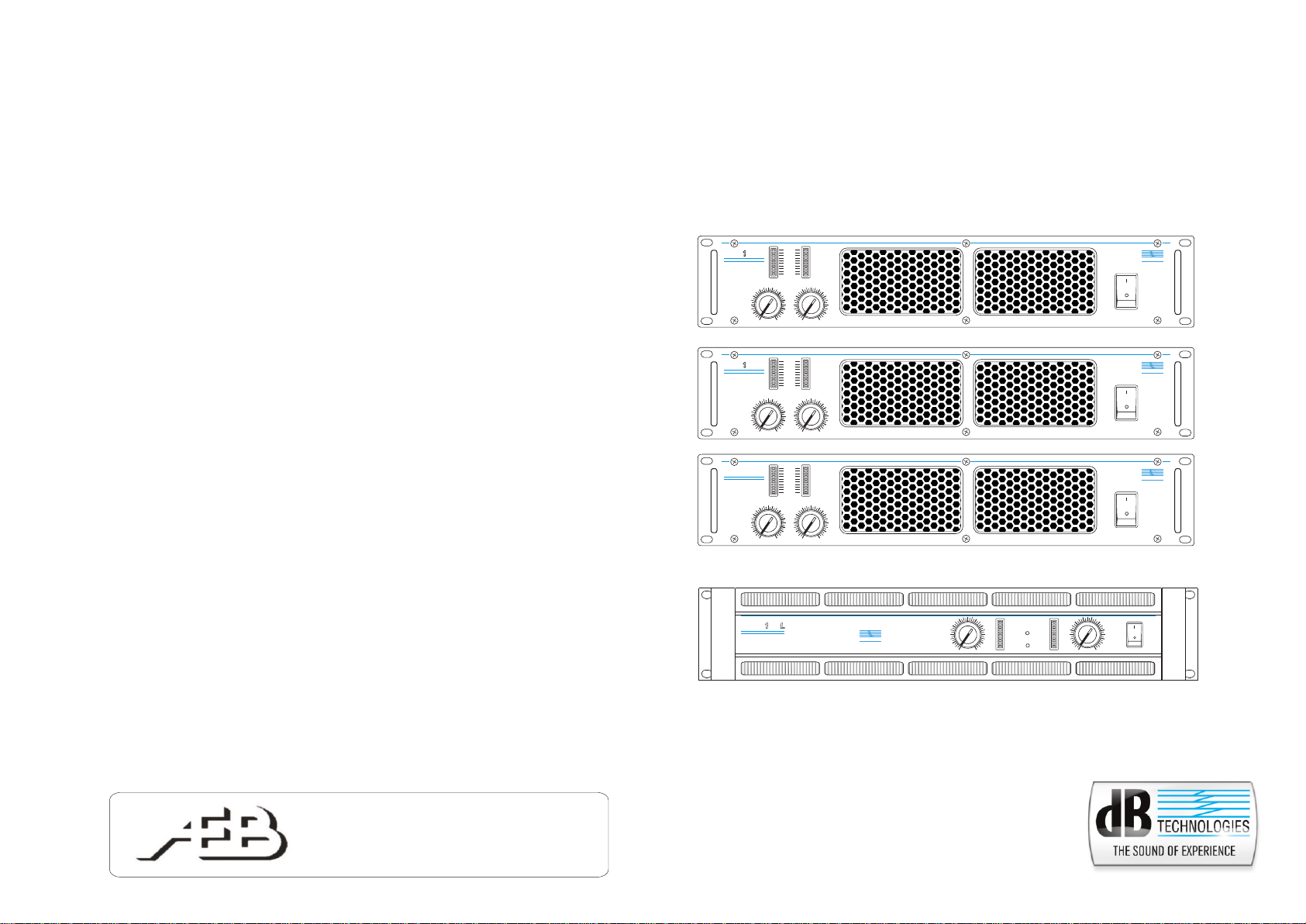
HPA series
PROFESSIONAL HIGH POWER AMPLIFIER
PROTECT
LIMIT
0 dB
0 0
0
HPA
HIGH POWER PROFESSIONAL AMPLIFIER
HPA
HIGH POWER PROFESSIONAL AMPLIFIER
28
HPA
HIGH POWER PROFESSIONAL AMPLIFIER
-3dB
-6dB
-9dB
-12dB
-18dB
-24dB
-30dB
CH1
0
0
-
0dB
4
0 0
CH1
0
0
-
0dB
0 0
CH1
0
0
-
0dB
CH2
0
0
-
0dB
PROTECT
LIMIT
0 dB
-3dB
-6dB
-9dB
-12dB
-18dB
-24dB
-30dB
CH2
0
0
-
0dB
PROTECT
LIMIT
0 dB
-3dB
-6dB
-9dB
-12dB
-18dB
-24dB
-30dB
CH2
0
0
-
0dB
d
POWER
d
POWER
d
POWER
TECHNOLOGIES
B
ON
OFF
TECHNOLOGIES
B
ON
OFF
TECHNOLOGIES
B
ON
OFF
A.E.B. Industriale S.r.l.
Via Brodolini, 8 - 40056 Crespellano (Bo) - ITALY
Tel. + 39 051969870 - Fax. + 39 051969725
Internet: www.dbtechnologies.com
E-mail: info@dbtechnologies.com
3 0 0
HPA
HIGH POWER PROFESSIONAL AMPLIFIER
420120152
d
TECHNOLOGIES
B
PROTECT
PROTECT
LIMIT
LIMIT
0 dB
0 dB
BRIDGE
-3dB
-3dB
-6dB
-6dB
-9dB
-9dB
-12dB
-12dB
POWER
-18dB
-18dB
-24dB
-24dB
-30dB
0
0
CH1
-30dB
0dB
0
0
--
0dB
ON
OFF
POWER
CH2
Page 2
IMPORTANTI ISTRUZIONI DI SICUREZZA
AVVERTENZA: PER RIDURRE IL RISCHIO DI SCOSSA
ItalianoItaliano
ATTENZIONE: PER RIDURRE IL RISCHIO DI INCENDIO O DI
ELETTRICA, NON TOGLIERE IL COPERCHIO
(O IL PANNELLO POSTERIORE). ALL’INTERNO
NON SONO CONTENUTE PARTI RIPARABILI
DALL’UTENTE; AFFIDARE LE RIPARAZIONI A
PERSONALE QUALIFICATO.
SC O SSA EL E TTR ICA , NO N ESP O RRE
QUESTO APPARECCHIO ALLA PIOGGIA O
ALL’UMIDITÀ.
Questo simbolo, dove compare, ha lo scopo di avvisare l’utente di presenza di tensione
pericolosa all’interno del prodotto che può essere di portata sufficiente a costituire un rischio di
scossa elettrica per le persone.
Questo simbolo, dove appare, ha lo scopo di avvisare l’utente di presenza di importanti
istruzioni d’uso e manutenzione (assistenza) nella documentazione che accompagna
l’apparecchio.
IMPORTANTE
Il presente manuale costituisce parte integrante del prodotto e deve accompagnare quest’ultimo anche
nei passaggi di proprietà, per permettere al nuovo proprietario di conoscere le modalità d’installazione e
d’utilizzo e le avvertenze per la sicurezza.
L’installazione ed utilizzo non in accordo con le prescrizioni e modalità contenute all’interno del presente
manuale d’uso esime il produttore da qualunque responsabilità di danni a persone, cose e strutture.
Leggere le seguenti istruzioni
Manuale d’usoManuale d’uso
Tutte le istruzioni di sicurezza e di funzionamento devono essere lette e comprese prima di mettere in
funzione l'apparato.
Tenere conto di tutti gli avvertimenti
Tutte le avvertenze sull'apparecchio e le istruzioni di funzionamento devono essere seguite fedelmente.
Inutilizzo prolungato dell’apparato
Nel caso in cui si preveda di non utilizzare l’apparato per lungo tempo, è buona norma disconnetterlo
dalla rete di alimentazione, riporlo nell’apposito imballo o ricoprirlo in maniera da evitarne l’esposizione
alla polvere.
Guasti e riparazioni
In caso di guasto dell’apparato, è assolutamente vietato per l'utente tentare di ripararlo o rimuovere il
coperchio protettivo. Disconnettere l’apparato dalla rete di alimentazione e contattare l’assistenza
tecnica per la riparazione.
PRECAUZIONI PER L’INSTALLAZIONE E PER L’UTILIZZO
GENERALITA’
Conservare le istruzioni
Ai fini di un corretto impiego dell’apparato, il presente manuale d’istruzioni deve essere mantenuto con
cura per ogni futura esigenza di consultazione.
Posizionamento dell’apparato
Collocare l’apparato in posizione stabile e sicura in modo da evitare situazioni di pericolo a cose,
persone e strutture.
Messa a terra di protezione
L’apparato è realizzato in Classe I di protezione contro la scossa elettrica e il collegamento alla rete di
alimentazione deve essere effettuato ad una presa provvista del conduttore di terra di protezione. Prima
di effettuare la connessione elettrica dell’apparato, assicurarsi che l’impianto di distribuzione di rete sia
conforme alle norme vigenti in materia di impianti elettrici.
Alimentazione
L'apparato deve essere collegato ad una sorgente di alimentazione del tipo e con le caratteristiche
indicate nei dati di targa riportati sull'apparecchio stesso e specificati nel presente manuale (Vedere
specifiche tecniche). Prima di collegare la spina di alimentazione assicurarsi che la tensione sia del tipo
richiesto dall’apparato.
Cavo di alimentazione
Al fine di garantire la sicurezza d’utilizzo dell’apparato utilizzare esclusivamente il cavo di alimentazione
fornito a corredo avendo cura di posizionarlo e proteggerlo in modo da evitarne il danneggiamento
durante l’utilizzo. In caso di danneggiamento contattare l’assistenza tecnica e richiederne la
sostituzione. Non utilizzare cavi diversi da quelli in dotazione.
"CAUTION"
TO PREVENT ELECTRICAL SHOCK
DO NOT REMOVE COVER
TO PREVENT RISK OF FIRE
REPLACE FUSES WITH
SAME TYPE AND RATINGS
THIS APPARATUS MUST BE EARTHED
"AVIS"
RISQUE DE CHOC ELECTRIQUE
NE PAS OUVRIR
POUR PREVENIR TOUT RISQUE DE FEU
REPLACER UN FUSIBLE
DE MÊME CARACTERISTIQUES
CET APPAREIL DOIT ÊNTRE RELIÉ A LA TERRE
Acqua e umidità
L'apparecchio non deve essere installato in prossimità di zone con presenza di liquidi ( es. lavandini,
lavabi, docce, vasche da bagno, bordo piscine, pavimenti bagnati o in altre posizioni in presenza di
acqua e liquidi in generale).
Penetrazione di oggetti e di liquidi
L’apparato deve essere posizionato in un luogo appropriato. Evitare di posizionare oggetti e contenitori
di liquidi sopra l’apparato, un ribaltamento accidentale potrebbe causarne l’intrusione all’interno delle
griglie di raffreddamento con conseguente pericolo elettrico.
Ventilazione
Installare l’apparecchio in una posizione o zona adeguata, tale da garantire un sufficiente ricircolo
d’aria. Non ostruire o coprire le feritoie di aerazione e ventilazione o i dissipatori dell’apparato. E’ buona
norma installare l’apparato ad una distanza che garantisca una buona ventilazione tra gli apparati.
Sorgenti di calore
Non installare o utilizzare l'apparecchio in prossimita’ di sorgenti di calore .
Accessori e optional
E’ assolutamente vietato perforare il contenitore dell’apparato o fissare qualunque altro genere di
supporto meccanico mediante adesivo. In caso di installazioni particolari e in ogni modo non descritte
nel presente manuale, contattare il servizio tecnico per l’elenco degli accessori disponibili per
l’apparato.
Seguire tutte le istruzioni
Tutte le istruzioni contenute nel presente manuale devono essere seguite da parte dll’utilizzatore per un
corretto utilizzo e funzionamento dell’apparato. In particolare si pone l’attenzione su:
- Non forzare gli organi di comando (tasti, controlli, ecc.).
- evitare di far lavorare l’apparato in sovraccarico per lungo tempo.
Pulizia
Pulire solo con un panno asciutto. Per la pulizia delle parti esterne evitare l’uso di diluenti, alcool,
benzina o altre sostanze volatili.
COLLEGAMENTI
ATTENZIONE
- Per il collegamento dell’apparecchio si raccomanda di rivolgersi a personale qualificato ed
addestrato, ossia personale avente conoscenze tecniche o esperienza o istruzioni specifiche
sufficienti per permettergli di realizzare correttamente le connessioni e prevenire i pericoli
dell’elettricità.
- Per evitare il rischio di shock elettrici, l’amplificatore deve essere alimentato dalla tensione di rete
solo dopo aver terminato tutti i collegamenti.
- Prima di alimentare l’amplificatore è buona norma ricontrollare tutte le connessioni.
- Tutto l’impianto di sonorizzazione dovrà essere realizzato in conformità con le norme e le leggi
vigenti in materia di impianti elettrici.
SUGGERIMENTI
ATTENZIONE
- Per evitare che fenomeni induttivi diano luogo a ronzii, disturbi e compromettano il risultato
dell’installazione, i cavi che trasmettono segnali microfonici o segnali a livello linea (es. 0 dB/V)
devono essere schermati e non devono essere posti in prossimità di:
1) apparecchiature che producono forti campi magnetici (es. grossi trasformatori di
alimentazione).
2) conduttori dell’energia elettrica.
3) linee che alimentano diffusori.
1 2
ItalianoItaliano
Manuale d’usoManuale d’uso
Page 3

1 COMANDI E FUNZIONI
1.1 Pannello frontale
1. INTERRUTTORE GENERALE
Questo interruttore accende e spegne l’apparecchio interrompendo entrambe le
fasi di alimetazione.
ItalianoItaliano
Manuale d’usoManuale d’uso
3 4
2. CONTROLLI DI VOLUME
Questi controlli permettono di dosare separatamente il volume dei due canali.
Nella configurazione MONO e BRIDGE utilizzare solo il CH1 e posizionare al
minimo il CH2.
3. INDICATORI DI PROTEZIONE - “PROTECTION”
Questi indicatori luminosi di colore rosso sono attivi in caso di presenza di tensione
continua, radio disturbi o frequenze subsoniche o anche quando si verifica una
situazione di sovracorrente.
Tale situazione è causata di solito da un cortocircuito presente sulle uscite
dell’apparecchio o da una impedenza troppo bassa dei diffusori.
4. INDICATORE DI PICCO - “LIMITER”
Questi indicatori luminosi di colore giallo indicano il raggiungimento del massimo
livello di amplificazione, con relativa limitazione nel caso di LIMITER attivato.
Una continua accensione degli stessi indica un eccessivo segnale di ingresso.
5. INDICATORI DI LIVELLO
Questi indicatori di colore verde si illuminano progressivamente indicando i livelli
d’uscita da -30dB a 0dB.
6. GRIGLIE DI ASPIRAZIONE
Queste griglie permettono il raffreddamento dell’amplificatore.
Non ostruire l’accesso e pulire le griglie quando necessita.
7. INDICATORE DI CONFIGURAZIONE BRIDGE - “BRIDGE” (solo HPA3100L )
Questo indicatore luminoso di colore giallo indica che l’amplificatore è stato
configurato per l’utilizzo in modo “BRIDGE”, tramite il selettore dedicato sul
pannello posteriore.
8. INDICATORE DI ALIMENTAZIONE - “POWER” ( solo HPA3100L )
Questo indicatore luminoso di colore verde indica l’accensione dell’amplificatore.
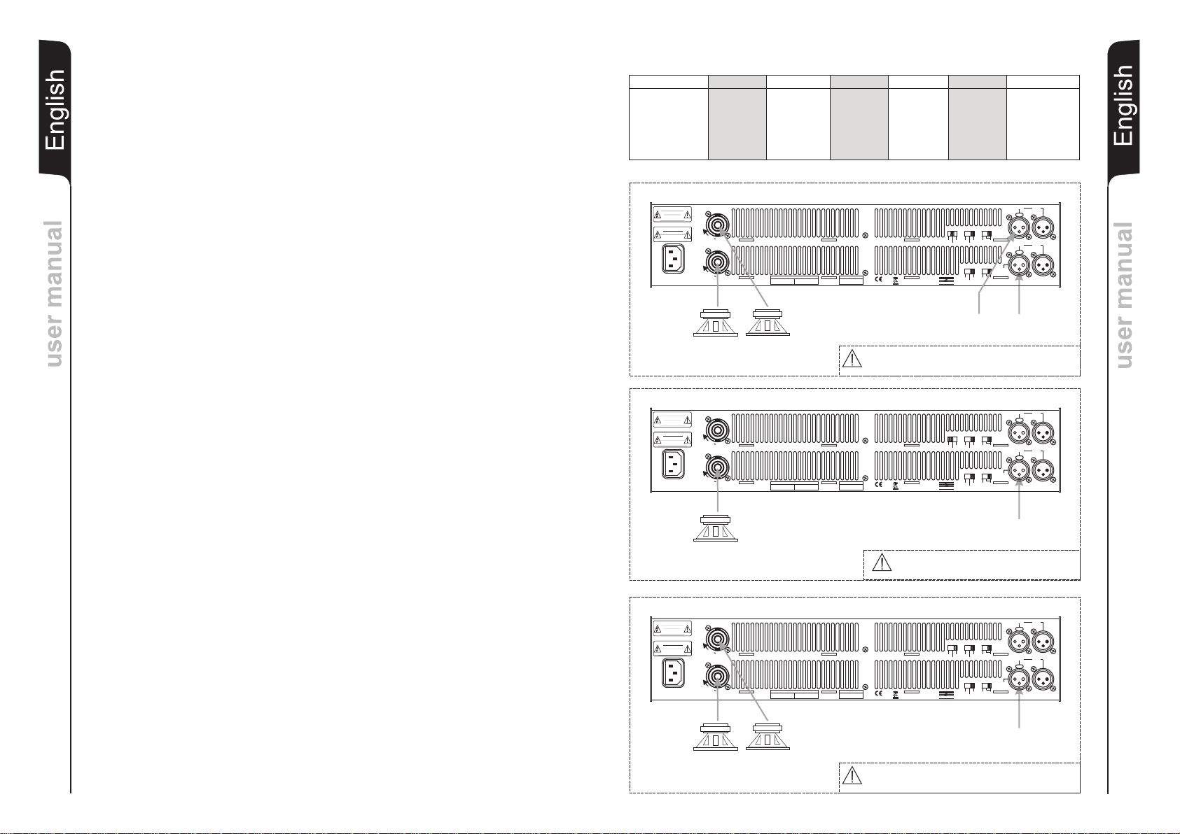
1.2 Pannello posteriore
1. PRESA DI ALIMENTAZIONE
Consente la connessione del cavo di alimentazione fornito in dotazione.
2. CONNETTORE SPEAK-ON uscita CH1
Utilizzare questo connettore per prelevare il segnale amplificato del CH1 e il
segnale per la configurazione bridge.
3. CONNETTORE SPEAK-ON uscita CH2
Utilizzare questo connettore per prelevare il segnale amplificato del CH2.
4. SELETTORE DI CONFIGURAZIONE - “MODE”
Questo selettore a tre posizioni permette di selezionare la configurazione
dell’amplifictore (MONO-STEREO-BRIDGE)
5. COMMUTATORE SENSIBILITA’ INGRESSO - “GAIN SENSITIVITY”
Questo interruttore a tre posizioni permette di selezionare la sensibilità in ingresso
(26dB - 32dB - 1,4V) ed è indipendente su ogni canale.
Selezionando 26dB o 32dB si ottiene lo stesso guadagno in ingresso per tutti i
modelli.
Selezionando 1,4V si ottiene la medesima sensibilità in ingresso per tutti i modelli.
6. COMMUTATORE LIMITER - “LIMITER”
Questo interruttore a due posizioni permette di attivare e disattivare il limiter interno
ed è indipendente su ogni canale.
7. CONNETTORE XLR ingresso CH1
Utilizzare questo connettore per pilotare il canale CH1 con un segnale bilanciato o
2 PROTEZIONI
2.1 Protezioni termiche
2.2 Protezioni DC/RFI
2.3 Protezioni corto circuito
2.4 Limiter (selezionabile)
sbilanciato. Per la configurazione MONO e BRIDGE utilizzare solo il CH1.
8. CONNETTORE XLR link CH1
Questo connettore è collegato in parallelo al INPUT CH1 (7) e può essere utilizzato
per rinviare il segnale audio ad altri amplificatori.
9. CONNETTORE XLR ingresso CH2
Utilizzare questo connettore per pilotare il canale CH2 con un segnale bilanciato o
sbilanciato.
10. CONNETTORE XLR link CH2
Questo connettore è collegato in parallelo al INPUT CH2 (9) e può essere utilizzato
per rinviare il segnale audio ad altri diffusori amplificati, registratori o amplificatori
supplementari.
11. GRIGLIE DI ASPIRAZIONE
Queste griglie permettono il raffreddamento dell’amplificatore.
Non ostruire l’accesso e pulire le griglie quando necessita.
Nel caso si verifichi una situazione di surriscaldamento dell’amplificatore (temperature
> 105°C), questo si proteggerà ponendo in “mute” il segnale audio in ingresso fino al
raggiungimento delle condizioni di normale funzionamento. Tale intervento verrà
segnalato con l’accensione dell’ indicatore rosso PROTECT posto sul frontale
dell’apparecchio.
E’ presente anche una protezione termica per il trasformatore toroidale che garantisce
la sicurezza anche nelle più esasperate condizioni di utilizzo. L’intervento di tale
protezione indica l’uso al limite delle caratteristiche e si proteggerà come indicato in
precedenza.
La riaccensione e la ripresa di tutte le funzioni è automatica al raggiungimento delle
normali temperature di esercizio. Il tempo di protezione può essere molto lungo
soprattutto nel caso di intervento di protezione termica sul trasformatore visto che il
nucleo impiegherà molto tempo a dissipare il calore accumulato.
Gli amplificatori sono provvisti di un circuito elettronico di protezione. Tale dispositivo
protegge gli altoparlanti in caso di tensione continua, radio-disturbi, frequenze
subsoniche e svolgono anche una funzione di anti-bump nella fase di accensione
dell’amplificatore.
L’intervento di tale protezione viene segnalato tramite l’accensione dell’indicatore
rosso, sul pannello frontale dell’amplificatore, che riporta la dicitura PROTECT.
La ripresa delle normali funzioni avverrà automaticamente quando la situazione di
disturbo verrà rimossa.
Gli amplificatori sono provvisti di protezione contro il corto circuito in uscita. Tale
protezione pone in stato di “mute” il segnale d’ingresso intervallandolo con tentativi di
ripristino del segnale (circa ogni 3-4 secondi).
La normale ripresa del funzionamento dell’amplificatore avverrà automaticamente
quando la condizione di corto circuito sarà rimossa.
Questa protezione si attiva anche nel caso in cui l’apparecchio stia erogando troppa
corrente (impedenza di carico troppo bassa).
Negli amplificatori sono presenti due circuiti limiter che assicurano un corretto
funzionamento del segnale in ingresso fino a + 10 dB dal valore di sensibilità corretta.
Tali dispositivi oltre che ad ottimizzare il lavoro dell’amplificatore, proteggono i diffusori
da segnali distorti che potrebbero danneggiarli.
ItalianoItaliano
Manuale d’usoManuale d’uso
Page 4
3. INSTALLAZIONI
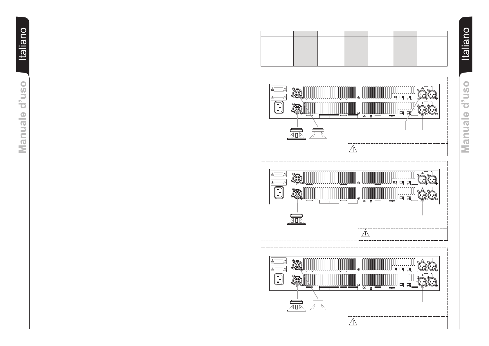
3.1 Configurazione STEREO
Porre il selettore MODE sulla posizione STEREO utilizzando entrambi gli ingressi audio
ed i relativi controlli di volume (FIG. 1, per connessione delle uscite FIG.A) .
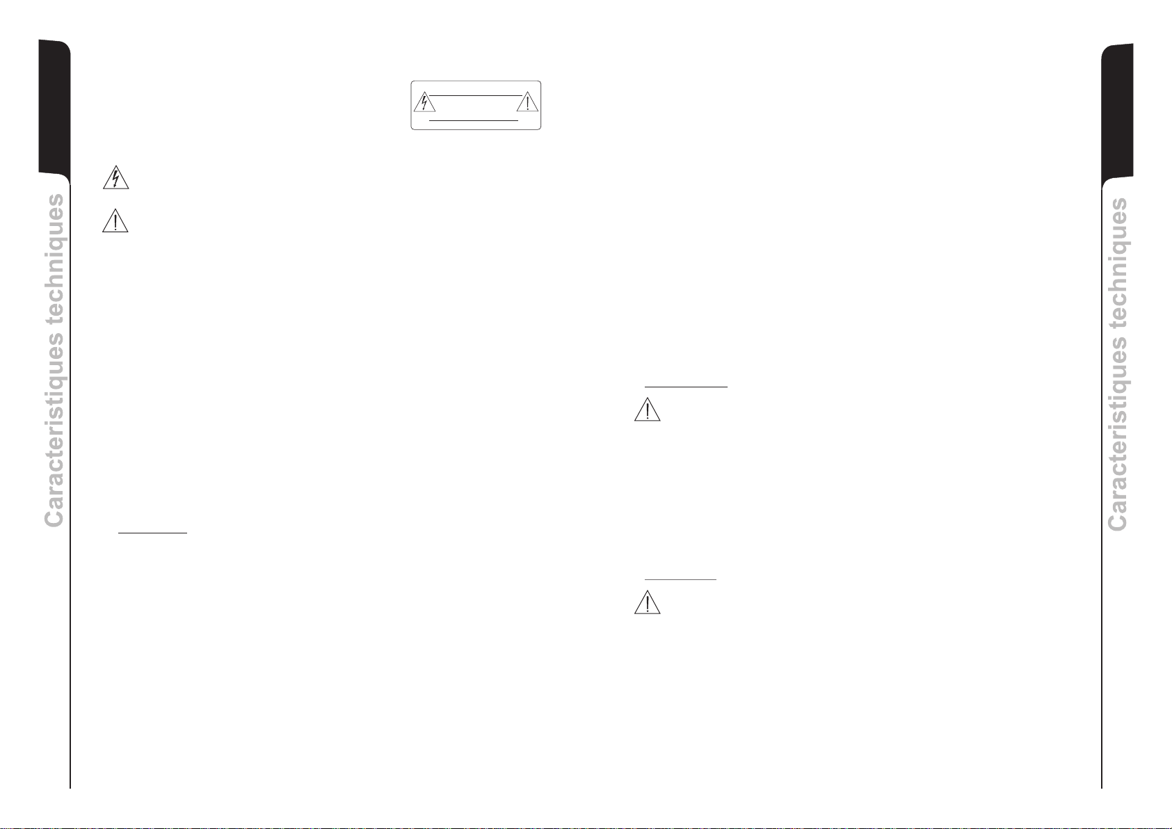
3.2 Configurazione BRIDGE
ItalianoItaliano
Porre il selettore MODE sulla posizione BRIDGE utilizzando solo l’ingresso audio CH1.
Il controllo del volume del CH1 controllerà il volume generale di uscita (FIG. 2).
Prelevare il segnale di uscita solo dal connettore CH1 (per connessione dell’uscita
FIG.B). Posizionare il controllo di volume CH2 al minimo.
3.3 Configurazione MONO
Porre il selettore MODE sulla posizione MONO, posto sul retro dell’amplificatore ,e
utilizzare solo l’ingresso audio CH1. Il controllo di volume CH1 controllerà il volume di
entrambe i canali ( FIG. 3).
Questa configurazione è particolarmente adatta per il collegamento di più diffusori
pilotati dallo stesso segnale (per connessioni delle uscite FIG. A)
3.4 Note per l’installazione
Gli amplificatori della serie HPA sono disegnati per essere alloggiati in contenitori
RACK standard, dimensione minima 2 unità rack. Se l’installazione viene effettuata
all’interno di un mobile RACK è consigliabile utilizzare anche i fissaggi predisposti sul
retro dell’amplificatore per evitare che il pannello frontale debba sopportare tutto il peso
Manuale d’usoManuale d’uso
dell’apparecchio.
Assicurarsi di garantire una adeguata aerazione per permettere all’amplificatore di
raffreddarsi in modo corretto. Non ustruire la parte posteriore dell’amplificatore per
garantire la necessaria quantità d’aria.
3.5 Collegamento alla rete di alimentazione
L’apparecchio dovrà essere collegato ad una rete di alimentazione che possa erogare
almeno la massima potenza richiesta. Non devono essere interposte prolunghe o
riduzioni, che pregiudichino le corretta erogazione di corrente.
3.6 Raffreddamento
Il raffreddamento è gestito da un circuito che regola automaticamente la velocità della
ventola in relazione all’aumento della temperatura. Così facendo si riduce al minimo il
rumore della ventola durante l’utilizzo.
Il raffreddamento è forzato e l’aria viene aspirata dal frontale e fuoriesce dal retro.
GAIN SENSITIVITY GAIN SENSITIVITY GAIN SENSITIVITY
HPA 1000 26dB 2,4V 32dB 1,2V 30,9dB 1,4V
HPA 1400 26dB 2,8V 32dB 1,4V 32,1dB 1,4V
HPA 2800 26dB 3,6V 32dB 1,8V 34,2dB 1,4V
HPA 3100L 26dB 4,0V 32dB 2,0V 35,1dB 1,4V
FIG.1
OUTPUT
FIG.2
OUTPUT
"CAUTION"
TO PREVENT ELECTRICAL SHOCK
DO NOT REMOVE COVER
TO PREVENT RISK OF FIRE
REPLACE FUSES WITH
SAME TYPE AND RATINGS
THIS APPARATUS MUST BE EARTHED
"AVIS"
RISQUE DE CHOC ELECTRIQUE
NE PAS OUVRIR
POUR PREVENIR TOUT RISQUE DE FEU
REPLACER UN FUSIBLE
DE MÊME CARACTERISTIQUES
CET APPAREIL DOIT ÊNTRE RELIÉ A LA TERRE
220-240V~ 50-60Hz
CH1
4W
"CAUTION"
TO PREVENT ELECTRICAL SHOCK
DO NOT REMOVE COVER
TO PREVENT RISK OF FIRE
REPLACE FUSES WITH
SAME TYPE AND RATINGS
THIS APPARATUS MUST BE EARTHED
"AVIS"
RISQUE DE CHOC ELECTRIQUE
NE PAS OUVRIR
POUR PREVENIR TOUT RISQUE DE FEU
REPLACER UN FUSIBLE
DE MÊME CARACTERISTIQUES
CET APPAREIL DOIT ÊNTRE RELIÉ A LA TERRE
220-240V~ 50-60Hz
CH1
8W
POWER
CONSUMPTION
230V~ 10A
2300W MAX
POWER
CONSUMPTION
2300W MAX
230V~ 10A
L
O
C
K
L
O
C
K
OUTPUT CHANNELS
L
O
C
K
L
O
C
K
OUTPUT CHANNELS
CH2
CH1
CH2
CH1
CONFIGURAZIONE STEREO
SERIAL NO.:
CH2
4W
BRIDGE MODE
1+ = speaker +
CH1
2+ = speaker -
MADE IN PRC
CH1
1+ = speaker +
1- = speaker -
MONO/STEREO MODE
CH2
OUTPUT
1+ = speaker +
1- = speaker -
HPA 1000 HPA 1400 OUTPUT:
HPA 2800 HPA 3100L OUTPUT:
CONFIGURAZIONE BRIDGE
SERIAL NO.:
MONO/STEREO MODE
1+ = speaker +
1+ = speaker +
CH1
CH2
1- = speaker -
1- = speaker -
BRIDGE MODE
1+ = speaker +
CH1
2+ = speaker -
MADE IN PRC
GAIN
MODE
LIMIT
SENSITIV ITY
1.4V
BRIDGE
OFF
26dB
MONO
ON
32dB
STEREO
GAIN
SENSITIV ITY
LIMIT
INPUT
BRIDGE
1.4V
OFF
26dB
ON
32dB
TECHNOLOGIES
d
B
INPUT
CH2
8W
GAIN
MODE
LIMIT
SENSITIV ITY
1.4V
BRIDGE
OFF
26dB
MONO
ON
32dB
STEREO
GAIN
SENSITIV ITY
LIMIT
INPUT
BRIDGE
1.4V
OFF
26dB
ON
32dB
TECHNOLOGIES
d
B
HPA 1000 HPA 1400 OUTPUT:
HPA 2800 HPA 3100L OUTPUT:
INPUT
CH1
8W
INPUT
CH1
INPUT
PUSH
INPUT
PUSH
INPUT CHANNELS
INPUT
PUSH
INPUT
PUSH
INPUT CHANNELS
4W
8W
8W
ItalianoItaliano
LINK
CH2
LINK
CH1
2W4W
LINK
CH2
LINK
CH1
4W
Manuale d’usoManuale d’uso
FIG.3
"CAUTION"
TO PREVENT ELECTRICAL SHOCK
DO NOT REMOVE COVER
TO PREVENT RISK OF FIRE
REPLACE FUSES WITH
SAME TYPE AND RATINGS
THIS APPARATUS MUST BE EARTHED
"AVIS"
RISQUE DE CHOC ELECTRIQUE
NE PAS OUVRIR
POUR PREVENIR TOUT RISQUE DE FEU
REPLACER UN FUSIBLE
DE MÊME CARACTERISTIQUES
CET APPAREIL DOIT ÊNTRE RELIÉ A LA TERRE
220-240V~ 50-60Hz
OUTPUT
CH1
4W
POWER
CONSUMPTION
230V~ 10A
2300W MAX
L
O
C
K
L
O
C
K
OUTPUT CHANNELS
CH2
CH1
5 6
CONFIGURAZIONE MONO
SERIAL NO.:
CH2
4W
BRIDGE MODE
1+ = speaker +
CH1
2+ = speaker -
CH1
1+ = speaker +
1- = speaker -
MONO/STEREO MODE
CH2
OUTPUT
1+ = speaker +
1- = speaker -
GAIN
MODE
SENSITIV ITY
BRIDGE
26dB
MONO
STEREO
GAIN
SENSITIV ITY
26dB
MADE IN PRC
d
B
TECHNOLOGIES
HPA 1000 HPA 1400 OUTPUT:
HPA 2800 HPA 3100L OUTPUT:
INPUT
LINK
CH2
PUSH
LIMIT
1.4V
OFF
ON
32dB
LIMIT
1.4V
OFF
ON
32dB
INPUT
BRIDGE
INPUT
8W
8W
INPUT
PUSH
INPUT CHANNELS
CH1
4W
LINK
CH1
2W4W
Page 5
IMPORTANT SAFETY INSTRUCTIONS
CAUTION: TO REDUCE THE RISK OF ELECTRICAL
WARNING: TO R E DUCE TH E R ISK OF FIRE OR
EnglishEnglish
IMPORTANT NOTES:
"CAUTION"
TO PREVENT ELECTRICAL SHOCK
SHOCK, DO NOT REMOVE THE COVER
(OR BACK). NO USER SERVICEABLE
PARTS INSIDE; REFER SERVICING TO
QUALIFIED PERSONNEL.
ELECTRICAL SHOCK. DO NOT EXPOSE
THIS APPLIANCE TO RAIN OR MOISTURE.
This symbol, wherever it appears, alerts you to the presence of uninsulated
dangerous voltage inside the enclosure - voltage that may be sufficient to constitute a
risk of shock.
This symbol wherever it appears, alerts you to important operating and maintenance
instructions in the accompanying literature. Read the manual.
DO NOT REMOVE COVER
TO PREVENT RISK OF FIRE
REPLACE FUSES WITH
SAME TYPE AND RATINGS
THIS APPARATUS MUST BE EARTHED
"AVIS"
RISQUE DE CHOC ELECTRIQUE
NE PAS OUVRIR
POUR PREVENIR TOUT RISQUE DE FEU
REPLACER UN FUSIBLE
DE MÊME CARACTERISTIQUES
CET APPAREIL DOIT ÊNTRE RELIÉ A LA TERRE
Object and Liquid Entry
The apparatus must be placed in anappropriate position. Care should be taken so that objects do not fall
and liquids are not spilled into the enclosure through cooling grid with consequent electrical danger.
Ventilation
The appliance should be situated so that its location or position does not interfere with its proper
ventilation. Do not block or cover any openings of the grid ventilation or heatsink. Install the apparatus at
a distance that ensures a good ventilation between devices.
Heat
Do not install the appliance near any source of heat.
Accessories and installation
For a safe installation, do not make any holes in the external chassis for the application of additional
brackets. In case of particular installations not described in this manual, contact technical service for
accessories specified by the manufacturer.
Follow the instructions
All operations and instructions in this user manual should be followed for a correct operation and function
of appliance. Pay attention in particular to:
- Never force the control elements (switches, controls, etc.).
- Do not force the amplifier to work in overload for extended periods of time.
Cleaning
Clean only with a dry cloth. Do not use solvents, alcohol, benzene or volatile substances for cleaning the
exterior parts.
EnglishEnglish
This manual is to be considered an integral part of the product, and must always accompany the
equipment when it changes ownership, as a reference for correct installation and operation as well as
for the safety regulations.The Manufacturing company will not assume any responsibility for incorrect
installation of the amplifier.
user manualuser manual
Read these instructions:
All the safety and operation instructions should be read before the appliance is operated.
Heed all Warnings:
All warnings on the appliance and in the operating instructions should be adhered to
Long period non use of equipment:
If long term non use of appliance is expected, it would be better to unplug this apparatus from power
supply, put it into proper packaging and cover to avoid dust exposure.
Damage and repair:
If apparatus has been damaged it is forbidden to repair it or to remove cover. Disconnect the unit from
the mains power and contact technical assistance for repair.
INSTALLATION AND OPERATING PRECAUTIONS
GENERAL
Keep these instructions:
For a correct use of the appliance, the safety and operating instructions should be retained for future
reference.
Apparatus positioning:
Make sure that the apparatus is positioned in a stable and secure way in order to avoid any dangerous
conditions for persons or objects.
Grounding protection:
The apparatus is made in protection CLASS I to prevent the risk of electrical shock the appliance must
be connected to a mains socket outlet with a protective earthing connection. Before making the
electrical connection of the appliance, ensure that the electrical distribution network conforms to the
regulations regarding electrical equipment.
Power Source
The appliance should be connected to a power supply only of the type described in the operating
instructions or as marked on the appliance (see “Specifications”). In order not to jeopardize the safety of
the amplifier, it must only be connected to the mains using the power cable provided.
Power Cord Protection:
To ensure a safe use of appliance, use only the power cord supplied with the equipment, taking care to
place it and protect it to avoid damage during use. If power cord becomes damaged contact technical
assistance and request replacement. Do not use cables other than supplied cables.
Water and Moisture:
Do not install this apparatus near water (e.g. near washbasins, sinks, showers, bathtubs, swimming
pool, wet floors or anything in the presence of water and liquids in general).
7
CONNECTION
CAUTION
- For connecting the appliance, use only qualified and experienced personnel having sufficient
technical knowledge or specific instructions for making the connections correctly and thus
preventing electrical dangers.
- To prevent the risk of electrical shock, the appliance must only be supplied from the mains after all
connections have been completed.
- Before powering up the appliance, it is advisable to re-check all the connections.
- The entire sound system must be designed and installed in compliance with the current standards
and regulations regarding electrical systems.
SUGGESTIONS
CAUTION
- To prevent inductive phenomena from giving rise to hum or disturbance which would jeopardize
efficient appliance operation, the cables that transmit microphone signals or line level signals
(e.g. 0 dB/V) must be screened and should not be run in the vicinity of:
1) Equipment that produces strong magnetic fields (e.g. large power supply transformers)
2) Electrical energy conductors
3) Lines that supply speakers.
user manualuser manual
8
Page 6

1 CONTROLS AND FUNCTIONS
1.1 Frontal Panel
1. MAINS SWITCH
This switch powers up and powers down the amplifier by cutting off both power
phases.
2. VOLUME CONTROLS
EnglishEnglish
user manualuser manual
These controls are used to regulate the volume of the two channels separately.
In the MONO and BRIDGE configuration, only use the CH1 and set CH2 to the
minimum.
3. PROTECTION INDICATORS - “PROTECTION”
These red LED indicates i.e. direct current, radio disturbances or subsonic
frequencies or also when an overcurrent situation occurs.
Such a situation is usually caused by a short circuit on the appliance outputs or by a
speaker impedance that is too low.
4. PEAK INDICATORS - LIMITER”
These yellow LED indicators tell you that the maximum amplification level has been
reached, with relevant limitation if LIMITER is active. The continuous illumination of
these indicators denotes an excessive input signal.
5. LEVEL INDICATORS
These green LED indicators progressively lighting up show output levels from 30dB to 0dB.
6. AIR INTAKE GRILLES
Air is sucked in through these grilles to cool the amplifier. Do not obstruct the grilles.
Clean the air filters when necessary.
7. BRIDGE CONFIGURATION INDICATOR “BRIDGE” (HPA3100L only)
The yellow LED indicator lighting up means that the amplifier is configurated for
“BRIDGE” mode use, it is selected from dedicated switch on rear panel.
8. POWER INDICATOR - “POWER” (HPA3100L only)
The green LED indicator lighting up indicates that the amplifier is operative.
1.2 Rear Panel
1. POWER CABLE SOCKET
For connecting the power cable supplied with the amplifer.
2. SPEAKON CONNECTOR (CH1 output)
Use this connector to take the CH1 amplified signal and the bridge configuration
signal.
3. SPEAKON CONNECTOR (CH2 output)
Use this connector to take the CH2 amplified signal.
4. CONFIGURATION MODE SELECTOR - “MODE”
Use this three-position selector to choose the required configuration mode (MONOSTEREO-BRIDGE).
5. INPUT SENSITIVITY SELECTOR - “ GAIN SENSITIVITY”
Use this three-position selector to choose the input sensitivity (26dB-32dB-1,4V), it
is indipendent for every channel.
Selecting 26dB or 32dB the input gain is the same for all models.
Selecting 1,4V obtain the same input sensitivity for all models.
6. LIMITER SELECTOR - “LIMITER”
Use this two-position switch to activate or deactivate the integrated limiter, it is
indipendent on every channel.
7. XLR CONNECTOR Input CH1
Use this XLR connector to pilot CH1 channel with balanced or unbalanced signal.
Use only CH1 for the MONO and BRIDGE configurations.
9
8. XLR CONNECTOR Link CH1
This XLR connector is in parallel connection to INPUT CH 1 (7), it is possible to use
to send audio signal to other amplifiers.
9. XLR CONNECTOR Input CH2
Use this XLR connector to pilot CH2 channel with balanced or unbalanced signal.
10. XLR CONNECTOR Link CH2
This XLR connector is in parallel connection to INPUT CH2 (9), it is possible to use
to send audio signal to other active loudspeaker, recorder or amplifiers.
11. AIR INTAKE GRILLES
Air is sucked in through these grilles to cool the amplifier. Do not obstruct the grilles.
Clean the air filters when necessary.
2. PROTECTION DEVICES
2.1 Thermal protection devices
If the amplifier overheats (temperature >105°C), the amplifier will protect itself by setting
the input audio signal to "mute" mode until normal operating conditions are restored.
This is shown by the PROTECT red LED indicator on front panel .
All models are fitted with a thermal protection device for the toroidal transformer,
ensuring safety even in the most severe operating conditions. The activation of this
protection feature indicates machine utilisation at the extreme limits of the amp's
specifications and cutout will occur as before.
Subsequent power-up and restoration of all the functions is automatic and occurs when
the normal working temperature has been restored. The protection device intervention
time might be very long since the core of the transformer will take a long time to dissipate
the heat that has accumulated.
2.2 DC/RFI protection devices
All the amplifier models are provided with relays on the audio outputs. These devices
protect the speakers in the case of direct current, radio disturbances and subsonic
frequencies and they also perform an anti-bump function when the amplifier is powered
up.
The tripping of this cutout is indicated by the lighting up of the red indicator on the front
panel of the amplifier, marked PROTECT.
Normal operations are restored automatically when the interference is eliminated.
2.3 Short-circuit protection devices
The amplifiers feature output short circuit cutouts. Such cutout put in “mute” state the
input signal, this condition is interrupted by signal restoring attempts (about every 3-4
seconds).
Normal amplifier operation is restored automatically once the short-circuit has been
corrected.
This cutout also trips in the event of the appliance supplying too much current (load
impedance too low).
2.4 Limiter (selectable)
The models are fitted with two limiter circuits ensuring correct operation with input
signals up to +10dB from the correct sensitivity value. In addition to optimising the
amplifier's performance, these devices also protect the speakers against distorted
signals that might damage them.
EnglishEnglish
user manualuser manual
10
Page 7
3. INSTALLATION
3.1 STEREO configuration
Place the MODE switch in STEREO position using both audio inputs and relevant
volume controls (FIG. 1, for output connection FIG.A).
3.2 BRIDGE configuration
EnglishEnglish
Place the MODE switch in BRIDGE position using only audio input CH1. The CH1
volume control will control total output volume (FIG. 2). Take the output signal only from
connector CH1( output connection in FIG.B).
3.3 MONO configuration
Place the MODE switch on the back of the amplifier in MONO position and use only
audio input CH1. The CH1 volume control will control the volume of both channels
(FIG.3).
This configuration is especially suitable for connecting up several speakers piloted by
the same signal ( for output connection FIG.A)
3.4 Installation notes
The HPA series amplifiers are designed to be housed in standard 19” racks. The models
occupy 2 units. If the amplifier is installed inside a 19” rack, we recommend to use the
mounting facilities provided at the rear of the amplifier to prevent the front panel from
having to bear the entire weight of the equipment.
user manualuser manual
Make sure that sufficient ventilation is provided to allow the amplifier to cool correctly.
Do not obstruct the rear part of the amplifier as this would prevent correct air flow.
3.5 Connection to the mains power supply
The amplifier must be connected to a power mains able to supply at least the maximum
power output required. Do not use extensions or reductions which could compromise
the correct supply of current.
3.6 Cooling
The cooling is governed by a circuit which automatically regulates the speed of the fan in
relation to rises in temperature. This way, noise from the fan is reduced to the minimum.
Ventilation is forced and the air flow is from the front to the rear.
GAIN SENSITIVITY GAIN SENSITIVITY GAIN SENSITIVITY
HPA 1000 26dB 2,4V 32dB 1,2V 30,9dB 1,4V
HPA 1400 26dB 2,8V 32dB 1,4V 32,1dB 1,4V
HPA 2800 26dB 3,6V 32dB 1,8V 34,2dB 1,4V
HPA 3100L 26dB 4,0V 32dB 2,0V 35,1dB 1,4V
FIG.1
OUTPUT
FIG.2
OUTPUT
"CAUTION"
TO PREVENT ELECTRICAL SHOCK
DO NOT REMOVE COVER
TO PREVENT RISK OF FIRE
REPLACE FUSES WITH
SAME TYPE AND RATINGS
THIS APPARATUS MUST BE EARTHED
"AVIS"
RISQUE DE CHOC ELECTRIQUE
NE PAS OUVRIR
POUR PREVENIR TOUT RISQUE DE FEU
REPLACER UN FUSIBLE
DE MÊME CARACTERISTIQUES
CET APPAREIL DOIT ÊNTRE RELIÉ A LA TERRE
220-240V~ 50-60Hz
CH1
4W
"CAUTION"
TO PREVENT ELECTRICAL SHOCK
DO NOT REMOVE COVER
TO PREVENT RISK OF FIRE
REPLACE FUSES WITH
SAME TYPE AND RATINGS
THIS APPARATUS MUST BE EARTHED
"AVIS"
RISQUE DE CHOC ELECTRIQUE
NE PAS OUVRIR
POUR PREVENIR TOUT RISQUE DE FEU
REPLACER UN FUSIBLE
DE MÊME CARACTERISTIQUES
CET APPAREIL DOIT ÊNTRE RELIÉ A LA TERRE
220-240V~ 50-60Hz
CH1
8W
POWER
CONSUMPTION
230V~ 10A
2300W MAX
POWER
CONSUMPTION
230V~ 10A
2300W MAX
L
O
C
K
L
O
C
K
OUTPUT CHANNELS
L
O
C
K
L
O
C
K
OUTPUT CHANNELS
CH2
CH1
CH2
CH1
STEREO CONFIGURATION
SERIAL NO.:
CH2
4W
BRIDGE MODE
1+ = speaker +
CH1
2+ = speaker -
CH1
1+ = speaker +
1- = speaker -
MONO/STEREO MODE
CH2
OUTPUT
1+ = speaker +
1- = speaker -
BRIDGE CONFIGURATION
SERIAL NO.:
MONO/STEREO MODE
1+ = speaker +
1+ = speaker +
CH1
CH2
1- = speaker -
1- = speaker -
BRIDGE MODE
1+ = speaker +
CH1
2+ = speaker -
GAIN
MODE
SENSITIV ITY
BRIDGE
26dB
MONO
STEREO
GAIN
SENSITIV ITY
26dB
MADE IN PRC
d
B
TECHNOLOGIES
INPUT
HPA 1000 HPA 1400 OUTPUT:
HPA 2800 HPA 3100L OUTPUT:
GAIN
MODE
SENSITIV ITY
BRIDGE
26dB
MONO
STEREO
GAIN
SENSITIV ITY
26dB
MADE IN PRC
TECHNOLOGIES
d
B
HPA 1000 HPA 1400 OUTPUT:
HPA 2800 HPA 3100L OUTPUT:
1.4V
32dB
1.4V
32dB
CH2
1.4V
32dB
1.4V
32dB
INPUT
PUSH
LIMIT
OFF
ON
INPUT
PUSH
LIMIT
INPUT
BRIDGE
OFF
ON
INPUT CHANNELS
INPUT
CH1
8W
8W
INPUT
PUSH
LIMIT
OFF
ON
INPUT
PUSH
LIMIT
INPUT
BRIDGE
OFF
ON
INPUT CHANNELS
INPUT
CH1
4W
8W
8W
EnglishEnglish
LINK
CH2
LINK
CH1
2W4W
LINK
CH2
LINK
CH1
4W
user manualuser manual
11
FIG.3
OUTPUT
"CAUTION"
TO PREVENT ELECTRICAL SHOCK
DO NOT REMOVE COVER
TO PREVENT RISK OF FIRE
REPLACE FUSES WITH
SAME TYPE AND RATINGS
THIS APPARATUS MUST BE EARTHED
"AVIS"
RISQUE DE CHOC ELECTRIQUE
NE PAS OUVRIR
POUR PREVENIR TOUT RISQUE DE FEU
REPLACER UN FUSIBLE
DE MÊME CARACTERISTIQUES
CET APPAREIL DOIT ÊNTRE RELIÉ A LA TERRE
220-240V~ 50-60Hz
CH1
4W
POWER
CONSUMPTION
230V~ 10A
2300W MAX
L
O
C
K
L
O
C
K
OUTPUT CHANNELS
MONO CONFIGURATION
INPUT
INPUT
BRIDGE
INPUT
8W
8W
PUSH
INPUT
PUSH
INPUT CHANNELS
CH1
4W
LINK
CH2
LINK
CH1
2W4W
12
CH2
GAIN
MODE
LIMIT
SENSITIV ITY
1.4V
BRIDGE
OFF
d
B
STEREO
TECHNOLOGIES
26dB
MONO
ON
32dB
GAIN
SENSITIV ITY
LIMIT
1.4V
OFF
26dB
ON
32dB
SERIAL NO.:
CH1
CH2
4W
BRIDGE MODE
1+ = speaker +
CH1
2+ = speaker -
MADE IN PRC
CH1
1+ = speaker +
1- = speaker -
MONO/STEREO MODE
CH2
OUTPUT
1+ = speaker +
1- = speaker -
HPA 1000 HPA 1400 OUTPUT:
HPA 2800 HPA 3100L OUTPUT:
Page 8

SICHERHEITSHINWEISE
WARNUNG: U M S T RO M SC H LA G G E FA H R Z U
DeutschDeutsch
BedienungsanleitungBedienungsanleitung
13
ACHTUNG: UM BRAND- UND STROMSCHLAGGEFAHR
WICHTIG
Dieses Handbuch ist wesentlicher Bestandteil des Geräts und muss dieses auch bei Besitzerwechsel
begleite n, damit der neue Besitzer die Inst al lations- und Ge brauchshinwei se sowie die
Sicherheitshinweise kennt.
Die nicht mit den in diesem Handbuch enthaltenen Vorschriften und Modalitäten übereinstimmende
Installation und Verwendung entheben den Hersteller jeder Haftung für Personen-, Sach- und
Anlagenschäden.
Die folgenden Anweisungen lesen
Alle Sicherheits- und Betriebsanweisungen müssen vor der Inbetriebnahme des Geräts gelesen und
verstanden werden.
Alle Warnhinweise berücksichtigen
Alle Warnhinweise für das Gerät und die Betriebsanweisungen müssen getreu befolgt werden.
Längere Nichtbenutzung des Geräts
Wenn eine längere Nichtbenutzung des Geräts abzusehen ist, sollten Sie es vom Versorgungsnetz
abtrennen, es erneut in die entsprechende Verpackung legen oder es so zudecken, dass eine
Staubaussetzung vermieden wird.
Störfälle und Reparaturen
Bei Gerätestörfall ist es dem Benutzer strengstens untersagt, eine Reparatur zu versuchen bzw. den
Schutzdeckel zu entfernen. Das Gerät vom Versorgungsnetz abtrennen und für eine Reparatur mit
dem Kundendienst Kontakt aufnehmen.
VORSICHTSMASSNAHMEN FÜR INSTALLATION UND GEBRAUCH
ALLGEMEINES
Die Anleitungen aufbewahren
Für den korrekten Gebrauch des Geräts muss dieses Handbuch für alle zukünftigen Einsichtnahmen
sorgfältig erhalten werden.
Positionierung des Geräts
Das Gerät in einer stabilen und sicheren Position aufstellen, damit gefährliche Situationen für
Gegenstände, Personen und Anlagen vermieden werden.
Schutzerdung
Das Gerät wurde mit Schutzklasse 1 für den elektrischen Schlag hergestellt und der Anschluss an das
Versorgungsnetz muss mit einem Stecker vorgenommen werden, der mit einem Schutzerdleiter
versehen ist. Vor dem Stromanschluss des Geräts vergewissern Sie sich, dass die Anlage des
Verteilernetzes den in Sachen Elektroanlagen geltenden Richtlinien entspricht.
Netzanschluß
Das Gerät muss an eine Stromquelle mit den Eigenschaften angeschlossen werden, die in den auf
dem Gerät wiedergegebenen Kenndaten angegeben sind und in diesem Handbuch spezifiziert
werden (Siehe technische Spezifikationen). Vor dem Anschluss des Netzsteckers vergewissern Sie
sich, dass die Spannung der vom Gerät verlangten Spannung entspricht.
Stromkabel
Um einen sicheren Gerätegebrauch zu gewährleisten, nur das mitgelieferte Stromkabel verwenden
und darauf achten, dass es so positioniert und geschützt wird, dass Beschädigungen während des
Gebrauchs vermieden werden. Bei Beschädigung mit dem Kundendienst Kontakt aufnehmen und die
Auswechselung veranlassen. Keine anderen als die mitgelieferten Kabel verwenden.
VERMEIDEN, DEN DECKEL (UND DIE
RÜCKPLATTE) NICHT ENTFERNEN. DAS
GERÄT ENTHÄLT KEINE TEILE, DIE DER
B EN UT ZE R R E PA R I E R E N D A R F.
REPARATUREN STETS VOM FACHMANN
AUSFÜHREN LASSEN.
ZU VERMEIDEN, DAS GERÄT VOR REGEN
UND FEUCHTIGKEIT SCHÜTZEN.
Dieses Zeichen soll den Benutzer vor Gefahren durch die elektrische Spannung im
Gerät warnen. Diese elektrische Spannung ist so hoch, dass Stromschlaggefahr
besteht.
Dieses Symbol soll den Benutzer auf wichtige Bedienungs- und Wartungsanweisungen
(Kundendienst) in der dem Gerät beiliegenden Dokumentation hinweisen.
“CAUTION”
TO PREVENT ELECTRICAL SHOCK
DO NOT REMOVE COVER
“AVIS”
RISQUE DE CHOCH ELECTRIQUE
NE PAS OUVRIR
Wasser und Feuchtigkeit
Das Gerät darf nicht in Nähe von vorhandenen Flüssigkeiten (z. B. Spülbecken, Waschbecken,
Duschen, Badewannen, Schwimmbadrändern, nassen Fußböden oder generell in sonstigen
Positionen mit vorhandenem Wasser und Flüssigkeiten) installiert werden.
Eindringen von Gegenständen und Flüssigkeiten
Das Gerät muss einem geeigneten Ort positioniert werden. Das Positionieren von Gegenständen und
Flüssigkeitsbehälter auf dem Gerät vermeiden, ein ungewilltes Umkippen könnte ein Eindringen in
die Kühlgitter und demzufolge eine elektrische Gefahr verursachen.
Belüftung
Das Gerät an einem geeigneten Ort oder Bereich installieren, der eine ausreichende Luftzirkulation
gewährleistet. Die Belüftungs- und Ventilationsschlitze bzw. die Kühlkörper des Geräts weder
verstopfen noch bedecken. Es ist angebracht, das Gerät in einer Entfernung zu installieren, die eine
gute Belüftung unter den Geräten gewährleistet.
Wärmequellen
Das Gerät weder in Nähe von Wärmequellen installieren noch benutzen .
Zubehörteile und Optional
Es ist strengstens verboten, das Gehäuse des Geräts zu durchbohren oder irgendeine andere
mechanische Halterung mittels Klebestreifen zu befestigen. Bei Spezialinstallationen und für alle
nicht in diesem Handbuch beschriebenen Weisen wenden Sie sich bitte für die für dieses Gerät
lieferbaren Zubehörteile an den technischen Kundendienst.
Alle Anweisungen befolgen
Alle in diesem Handbuch enthaltenen Anweisungen müssen für einen korrekten Gebrauch und
Betrieb des Geräts vom Benutzer befolgt werden. Insbesondere muss auf Folgendes geachtet
werden:
- Die Bedienelemente (Tasten, Kontrollvorrichtungen, usw.) nicht forcieren.
- Den Betrieb über eine lange Zeit in Überlast vermeiden.
Reinigung
Nur mit einem trockenen Tuch reinigen. Für die Reinigung der Außenteile den Gebrauch von
Verdünnungsmitteln, Alkohol, Benzin oder anderen flüchtigen Substanzen vermeiden.
ANSCHLÜSSE
ACHTUNG
- Es wird empfohlen, sich für den Anschluss der Lautsprecherbox an qualifiziertes und
ausgebildetes Personal zu wenden oder aber an Personal, das über eine ausreichende
technische Ausbildung und über die entsprechenden Kenntnisse verfügt, um die Anschlüsse
korrekt auszuführen und die aus der elektrischen Energie hervorgehenden Gefahren zu
vermeiden.
- Zur Vermeidung der Gefahr von elektrischen Schlägen dürfen die Lautsprecher erst nach der
Ausführung sämtlicher Anschlussarbeiten an die Netzspannung angeschlossen werden.
- Vor dem Anlegen der Netzspannung sollten sämtliche Anschlüsse nochmals kontrolliert
werden und insbesondere muss sichergestellt werden, dass keine versehentlichen
Kurzschlüsse vorhanden sind
- D ie ges amt e Be sch all ung san lage mu ss in Übe rei nst imm ung mit den gel ten den
Normbestimmungen und Gesetzen für elektrische Anlagen ausgeführt werden.
TIPPS
ACHTUNG
- Zur Vermeidung von Induktionsphänomenen, die zu Brummen und Störungen führen und den
ordnungsgemäßen Betrieb der Lautsprecherbox stören, müssen die Kabel, die die
Mikrofonsignale oder Signale mit Linepegel übertragen (zum Beispiel 0 dB/V) abgeschirmt
sein und sie dürfen nicht in der Nähe von:
1) Geräten, die starke Magnetfelder erzeugen (zum Beispiel Leistungstransformatoren);
2) elektrischen Leistungskabeln;
3) Leitungen, die Lautsprecher versorgen, verlegt werden.
ItalianoItalianoItalianoItaliano
DeutschDeutsch
Español
BedienungsanleitungBedienungsanleitung
ESPA OLÑ
ESPA OLÑ ESPA OLÑ ESPA OLÑ
14
Page 9

1 BEDIENELEMENTE UND FUNKTIONEN
1.1 Frontplatte
1. NETZSCHALTER
Dieser Schalter dient zum Ein- und Ausschalten des Geräts. Es werden sowohl der
Phasen- und der Neutralleiter unterbrochen.
2. LAUTSTÄRKEREGLER
DeutschDeutsch
BedienungsanleitungBedienungsanleitung
Mit diesen Reglern kann die Lautstärke der beiden Kanäle separat eingestellt
werden. Bei der Konfiguration MONO und BRIDGE nur CH1 verwenden und CH2
auf das Minimum positionieren (ganz nach links drehen).
3. ANZEIGEN DER SCHUTZSCHALTUNGEN - ”PROTECTION ”
Diese roten Anzeige leuchtet auf bei vorhandener Dauerspannung, Funkstörungen
oder Infraschallfrequenzen bzw. auch wenn eine Überstromsituation eintritt.
Zum Ansprechen des Überstromschutzes kommt es im Allgemeinen bei einem
Kurzschluss an den Ausgängen des Geräts oder bei einer zu niedrigen Impedanz der
Lautsprecher.
4. PEAK-ANZEIGE - ”LIMITER”
Di e se gelbe n L EDs sign alisie ren das Er r eiche n d e s maxim a len
Verstärkungspegels, mit entsprechender Begrenzung bei eingeschaltetem
LIMITER.
Wenn sie ständig leuchten, bedeutet dies, dass das Eingangssignal zu hoch ist.
5. PEGELANZEIGEN
Die grünen LEDs leuchten fortlaufend auf und zeigen die Aussteuerung von -30dB
bis 0dB an.
6. LÜFTUNGSGITTER
Dieses Gitter ermöglicht die Kühlung des Verstärkers. Die Lüftungsgitter dürfen
keinesfalls abgedeckt werden und müssen bei Bedarf gesäubert werden.
7. ANZEIGE FÜR KONFIGURATION - “BRIDGE” (nur HPA3100L )
Diese gelbe LED gibt an, dass der Verstärker mit dem entsprechenden
Wählschalter auf der Rücktafel für die Verwendung im “BRIDGE”-Modus
konfiguriert wurde.
8. STROMANZEIGE - “POWER” ( nur HPA3100L )
Die grüne LED zeigt den Zustand “EIN” des Verstärkers an.
1.2 Rückseite
1. NETZ-EINBAUSTECKER
Für den Anschluss des beiliegenden Netzkabels.
2. SPEAKON-ANSCHLUSS Ausgang CH1
Ausgang des Verstärkersignal CH1 und des Signals für den Brückenbetrieb.
3. SPEAKON-ANSCHLUSS Ausgang Ch2
Ausgang des Verstärkersignal CH2.
4. BETRIEBSARTENSCHALTER
Dieser Schalter hat drei Schaltstellungen und dient zum Einstellen der
Betriebsarten (MONO-STEREO-BRIDGE).
5. UMSCHALTER FÜR EINGANGSEMPFINDLICHKEIT - “GAIN SENSITIVITY”
Dieser Dreipositionenschalter ermöglicht die Wahl der Eingangsempfindlichkeit
(26dB - 32dB - 1,4V) und ist für jedem Kanal unabhängig einstellbar.
Durch Wahl von 26dB oder 32dB erhalten Sie denselben Verstärkungsfaktor im
Eingang für alle Modelle. Durch Wahl von 1,4V erhalten Sie dieselbe
Empfindlichkeit im Eingang für alle Modelle.
6. SCHALTER - “LIMITER”
Dieser Zweipositionenschalter ermöglicht das Ein- und Ausschalten des internen
Limiters und ist auf jedem Kanal unabhängig.
15
7. XLR Eingang CH1
Eingangsbuchse des Kanals CH1 für ein symmetrisches oder unsymmetrisches
Eingangssignal.
Für die Konfiguration MONO und BRIDGE nur den Eingang CH1 verwenden!
8. XLR Link CH1
Diese Buchse ist parallel an INPUT CH1 (7) angeschlossen und kann für die
Weiterleitung des Signals an andere Verstärker verwendet werden.
9. XLR Eingang CH2
Eingangsbuchse des Kanals CH2 für ein symmetrisches oder unsymmetrisches
Eingangssignal..
10. XLR Link CH2
Diese Buchse ist parallel an INPUT CH2 (9) angeschlossen und kann für die
Weiterleitung des Signals an andere Verstärker verwendet werden.
11. LÜFTUNGSGITTER
Dieses Gitter ermöglicht die Kühlung des Verstärkers. Es darf keinesfalls
abgedeckt werden und muss bei Bedarf gesäubert werden.
2. SCHUTZSCHALTUNGEN
2.1 Thermische Schutzschaltungen
Bei Überhitzung des Verstärkers (Temperatur > 105°C) wird das Audiosignal am
Eingang stummgeschaltet (Mute), bis wieder normale Betriebsbedingungen vorliegen.
Dieser Eingriff wird durch das Aufleuchten der roten Anzeige PROTECT auf der
Vorderseite des Geräts angezeigt.
Es gibt auch eine thermische Schutzschaltung für den Ringkerntransformator, die auch
bei schwersten Betriebsbedingungen die Sicherheit garantiert. Wenn diese
Schutzschaltung anspricht, heißt das, dass das Gerät an den Grenzen seiner
Leistungsfähigkeit betrieben wird. Der Schutz wird wie zuvor beschrieben realisiert.
Die Wiedereinschaltung und die Wiederaufnahme aller Funktionen erfolgen
automatisch, wenn die Betriebstemperatur wieder einen normalen Wert erreicht hat.
Die Dauer der Schutzabschaltung kann sehr lang sein; dies gilt vor allem bei
Ansprechen der thermischen Schutzschaltung des Transformators, da es sehr lange
dauert, bis der Kern die gespeicherte Wärme wieder abgegeben hat.
2.2 Schutzschaltungen DC/RFI
Die Verstärker sind mit einem Elektronikschutzkreis ausgestattet. Diese Schutzrelais
sc hützen die La utsp reche r gege n Gleichspa nnun g, Hoch freq uenzstö
rungen und subsonic (Infraschall) Frequenzen; ferner fungieren sie als Schutz gegen
den Einschaltstromstoß beim Einschalten des Verstärkers.
Das Ansprechen dieser Schutzschaltung wird durch das Aufleuchten der roten LED mit
der Kennzeichnung PROTECT auf der Frontplatte des Verstärkers signalisiert.
Die normalen Funktionen werden nach Beseitigung der Störung automatisch wieder
aufgenommen.
2.3 Schutzschaltungen gegen Kurzschluss
Die Verstärker sind gegen Kurzschluss am Ausgang geschützt. Dieser Schutz versetzt
das Eingangssignal in den Zustand “MUTE”, wobei er durch Versuche zur
Wiederherstellung des Signals unterbrochen wird (zirka alle 3-4 Sekunden)
Der Verstärker nimmt den normalen Betrieb nach Beseitigung des Kurzschlusses
automatisch wieder auf.
Diese Schutzschaltung spricht auch dann an, wenn das Gerät zu viel Strom abgibt (zu
niedrige Lastimpedanz).
ItalianoItalianoItalianoItaliano
DeutschDeutsch
Español
BedienungsanleitungBedienungsanleitung
ESPA OLÑ
ESPA OLÑ ESPA OLÑ ESPA OLÑ
16
Page 10

2.4 Limiter (Wählbar)
Die Verstärker verfügen über zwei Limiter-Schaltungen, die das einwandfreie
Funktionieren bis zur eingestellten Empfindlichkeit +10dB gewährleisten.
Diese Schutzschaltungen optimieren nicht nur den Betrieb des Verstärkers, sondern
schützen auch die Lautsprecher vor einer Beschädigung durch verzerrte Signale.
3. INSTALLATION
DeutschDeutsch
3.1 STEREO-Betrieb
Den Betriebsartenschalter MODE in die Schaltstellung STEREO schalten und beide
Audioeingänge sowie die zugehörigen Lautstärkeregler verwenden (ABB. 1/FIG..1 Für
Anschluss der Ausgänge Abb.A ).
3.2 BRIDGE-Betrieb
Den Betriebsartenschalter MODE in die Schaltstellung BRIDGE schalten und nur den
Audioeingang CH1 verwenden. Der Lautstärkeregler CH1 reguliert die gesamte
Ausgangslautstärke (ABB. 2/ FIG.2). Der Anschluss darf nur über SpeakonSteckverbinder efolgen.
Den Lautstärkeregler CH2 auf die Mindestlautstärke positionieren!
3.3 MONO-Betrieb
Den Betriebsartenschalter MODE auf der Rückseite des Verstärkers in die
Schaltstellung MONO schalten und nur den Audioeingang CH1 verwenden. Der
Lautstärkeregler CH1 dient zur Einstellung der Lautstärke beider Kanäle (ABB.
3/FIG.3).
Diese Betriebsart eignet sich besonders für den Betrieb mehrerer Lautsprecher, die mit
demselben Signal angesteuert werden (Für Anschluss der Ausgänge siehe Abb.1)
3.4 Hinweise zur Installation
Die Verstärker der Serie HPA sind für den Einbau in ein 19"-Rack (2 HE) ausgelegt.
BedienungsanleitungBedienungsanleitung
Beim Einbau in ein 19"-Rackl sollten auch die Befestigungen auf der Rückseite des
Verstärkers verwendet werden, damit die Frontplatte nicht das ganze Gewicht des
Geräts tragen muss.
Sicherstellen, dass eine ausreichende Lüftung gewährleistet ist, um die
ordnungsgemäße Kühlung des Verstärkers zu gestatten. Die Rückseite des
Verstärkers darf nicht abgedeckt werden, damit stets eine ausreichende Luftzufuhr
gewährleistet ist.
3.5 Netzanschluss
Das Gerät muss an ein Stromnetz angeschlossen werden, das mindestens für seine
maximale Leistungsaufnahme ausgelegt sein muss. Die Verwendung von
Verlängerungen oder Reduzierkupplungen ist nicht erlaubt, um nicht die
ordnungsgemäße Stromversorgung des Geräts zu gefährden.
3.6 Kühlung
Die Kühlung wird von einem Drehzahlreguliertem Lüfter in Abhängigkeit zur
Temperaturzunahme reguliert. Hierdurch wird der Geräuschpegel des Lüfters während
des Betriebs auf ein Minimum reduziert.
Es handelt sich um eine Zwangskühlung; die Luft wird auf der Vorderseite angesaugt
und tritt auf den Rückseite aus.
GAIN SENSITIVITY GAIN SENSITIVITY GAIN SENSITIVITY
HPA 1000 26dB 2,4V 32dB 1,2V 30,9dB 1,4V
HPA 1400 26dB 2,8V 32dB 1,4V 32,1dB 1,4V
HPA 2800 26dB 3,6V 32dB 1,8V 34,2dB 1,4V
HPA 3100L 26dB 4,0V 32dB 2,0V 35,1dB 1,4V
FIG.1
OUTPUT
FIG.2
OUTPUT
FIG.3
"CAUTION"
TO PREVENT ELECTRICAL SHOCK
DO NOT REMOVE COVER
TO PREVENT RISK OF FIRE
REPLACE FUSES WITH
SAME TYPE AND RATINGS
THIS APPARATUS MUST BE EARTHED
"AVIS"
RISQUE DE CHOC ELECTRIQUE
NE PAS OUVRIR
POUR PREVENIR TOUT RISQUE DE FEU
REPLACER UN FUSIBLE
DE MÊME CARACTERISTIQUES
CET APPAREIL DOIT ÊNTRE RELIÉ A LA TERRE
220-240V~ 50-60Hz
CH1
4W
"CAUTION"
TO PREVENT ELECTRICAL SHOCK
DO NOT REMOVE COVER
TO PREVENT RISK OF FIRE
REPLACE FUSES WITH
SAME TYPE AND RATINGS
THIS APPARATUS MUST BE EARTHED
"AVIS"
RISQUE DE CHOC ELECTRIQUE
NE PAS OUVRIR
POUR PREVENIR TOUT RISQUE DE FEU
REPLACER UN FUSIBLE
DE MÊME CARACTERISTIQUES
CET APPAREIL DOIT ÊNTRE RELIÉ A LA TERRE
220-240V~ 50-60Hz
CH1
8W
"CAUTION"
TO PREVENT ELECTRICAL SHOCK
DO NOT REMOVE COVER
TO PREVENT RISK OF FIRE
REPLACE FUSES WITH
SAME TYPE AND RATINGS
THIS APPARATUS MUST BE EARTHED
"AVIS"
RISQUE DE CHOC ELECTRIQUE
NE PAS OUVRIR
POUR PREVENIR TOUT RISQUE DE FEU
REPLACER UN FUSIBLE
DE MÊME CARACTERISTIQUES
CET APPAREIL DOIT ÊNTRE RELIÉ A LA TERRE
220-240V~ 50-60Hz
POWER
CONSUMPTION
230V~ 10A
2300W MAX
POWER
CONSUMPTION
230V~ 10A
2300W MAX
POWER
CONSUMPTION
230V~ 10A
2300W MAX
L
O
C
K
L
O
C
K
OUTPUT CHANNELS
L
O
C
K
L
O
C
K
OUTPUT CHANNELS
L
O
C
K
L
O
C
K
OUTPUT CHANNELS
CH2
SERIAL NO.:
CH1
CH2
SERIAL NO.:
CH1
CH2
SERIAL NO.:
CH1
STEREO-BETRIEB
MONO/STEREO MODE
1+ = speaker +
1+ = speaker +
CH1
CH2
1- = speaker -
1- = speaker -
OUTPUT
CH2
4W
BRIDGE-BETRIEB
MONO/STEREO MODE
1+ = speaker +
1+ = speaker +
CH1
CH2
1- = speaker -
1- = speaker -
MONO-BETRIEB
MONO/STEREO MODE
1+ = speaker +
1+ = speaker +
CH1
CH2
1- = speaker -
1- = speaker -
BRIDGE MODE
1+ = speaker +
CH1
2+ = speaker -
MADE IN PRC
HPA 1000 HPA 1400 OUTPUT:
HPA 2800 HPA 3100L OUTPUT:
BRIDGE MODE
1+ = speaker +
CH1
2+ = speaker -
MADE IN PRC
BRIDGE MODE
1+ = speaker +
CH1
2+ = speaker -
MADE IN PRC
GAIN
MODE
LIMIT
SENSITIV ITY
1.4V
BRIDGE
OFF
26dB
MONO
ON
32dB
STEREO
GAIN
SENSITIV ITY
LIMIT
INPUT
BRIDGE
1.4V
OFF
26dB
ON
32dB
TECHNOLOGIES
d
B
INPUT
CH2
8W
GAIN
MODE
LIMIT
SENSITIV ITY
1.4V
BRIDGE
OFF
26dB
MONO
ON
32dB
STEREO
GAIN
SENSITIV ITY
LIMIT
INPUT
BRIDGE
1.4V
OFF
26dB
ON
32dB
TECHNOLOGIES
d
B
HPA 1000 HPA 1400 OUTPUT:
HPA 2800 HPA 3100L OUTPUT:
GAIN
MODE
LIMIT
SENSITIV ITY
1.4V
BRIDGE
OFF
26dB
MONO
ON
32dB
STEREO
GAIN
SENSITIV ITY
LIMIT
INPUT
BRIDGE
1.4V
OFF
26dB
ON
32dB
TECHNOLOGIES
d
B
INPUT
CH1
8W
INPUT
CH1
INPUT
PUSH
INPUT
PUSH
INPUT CHANNELS
INPUT
PUSH
INPUT
PUSH
INPUT CHANNELS
INPUT
PUSH
INPUT
PUSH
INPUT CHANNELS
4W
8W
8W
ItalianoItalianoItalianoItaliano
DeutschDeutsch
Español
LINK
CH2
LINK
CH1
2W4W
LINK
CH2
LINK
CH1
BedienungsanleitungBedienungsanleitung
4W
LINK
CH2
LINK
CH1
17
OUTPUT
CH1
4W
OUTPUT
CH2
4W
HPA 1000 HPA 1400 OUTPUT:
HPA 2800 HPA 3100L OUTPUT:
INPUT
8W
8W
CH1
4W
2W4W
18
Page 11
INSTRUCTIONS DE SÉCURITÉ
AVERTISSEMENTS: AFIN DE LIMI TER LES RISQU ES DE DÉCHA RGE
ATTENTION: AFIN DE RÉDUIRE LES RISQUES D'INCENDIE OU DE
Français
Ce symbole a la fonction de signaler à l'utilisateur, là où il est apposé, la présence de tension
dangereuse à l'intérieur du produit, avec une valeur suffisante pour représenter un risque de
décharge électrique pour les personnes.
Ce symbole, là où il est reporté, a la fonction de signaler à l'utilisateur la présence d'instructions
d'utilisation et entretien (assistance) importantes dans la documentation qui accompagne
l'appareil.
IMPORTANT
Le présent manuel fait partie intégrante du produit et doit accompagner celui-ci même en cas de
passage de propriété afin de permettre au nouveau propriétaire de connaître les modalités
d'installation et d'utilisation ainsi que les avertissements relatifs à la sécurité.
L'installation et l'utilisation qui ne sont pas conformes avec les prescriptions et modalités contenues
dans ce manuel d'emploi dégage le producteur de toute responsabilité en cas de dommages à
personnes, choses et structures.
Lire les instructions suivantes
Toutes les instructions de sécurité et de fonctionnement doivent être lues et comprises avant de mettre
l'appareil en fonction.
Tenir compte de tous les avertissements
Tous les avertissements concernant l'appareil et les instructions de fonctionnement doivent être
fidèlement suivis.
Inutilisation prolongée de l'appareil
Dans le cas où l'on prévoit de ne pas utiliser l'appareil pendant une longue période, il convient de le
débrancher du réseau électrique, le replacer dans son emballage et le recouvrir afin qu'il ne soit pas
exposé à la poussière.
Pannes et réparations
En cas de panne de l'appareil, il est absolument interdit pour l'utilisateur de tenter de le réparer ou de
retirer le couvercle de protection. Débrancher l'appareil du réseau d'alimentation et contacter
l'assistance technique pour la réparation.
PRECAUTIONS POUR L'INSTALLATION ET POUR L'UTILISATION
Caracteristiques techniquesCaracteristiques techniques
19
GENERALITES
Conserver les instructions
Pour une utilisation correcte de l'appareil, ce manuel d'instructions doit être maintenu avec soin pour
qu'il puisse être consulté ultérieurement.
Positionnement de l'appareil
Placer l'appareil en position stable et sûre de manière à éviter des situations de danger à choses,
personnes ou structures.
Mise à la terre de protection
L'appareil est réalisé en Classe I de protection contre la secousse électrique et le raccordement au
réseau électrique doit être fait à une prise dotée de conducteur de terre de protection. Avant d'effectuer
la connexion électrique de l'appareil, s'assurer que le système de distribution soit conforme aux
normes en vigueur en matière d'installations électriques.
Alimentation
L'appareil doit être branché à une source d'alimentation du type et dotée des caractéristiques
indiquées sur la plaque de l'appareil et spécifiées dans le présent manuel (Voir spécifications
techniques). Avant de brancher la fiche d'alimentation, s'assurer que la tension soit du type requis par
l'appareil.
Câble d'alimentation
Afin de garantir la sécurité d'utilisation de l'appareil, utiliser exclusivement le câble d'alimentation
fourni en ayant soin de le positionner et de le protéger pour ne pas l'endommager pendant l'utilisation.
En cas d'endommagement, contacter l'assistance technique et demande à ce qu'il soit changé. Ne pas
utiliser de câbles autres que ceux fournis.
ÉLECTRIQUE NE PAS ENLEVER LE COUVERCLE (OU
LE PAN NE A U A RRIÈR E) . LES C OMPOS AN TS
INTERNES NE PEUVENT PAS ÊTRE RÉPARÉS PAR
L'UTILISATEUR; CONFIER LES RÉPARATIONS À DU
PERSONNEL QUALIFIÉ.
DÉCHARGE ÉLECTRIQUE, NE PAS EXPOSER CET
APPAREIL À LA PLUIE OU À L'HUMIDITÉ.
“CAUTION”
TO PREVENT ELECTRICAL SHOCK
DO NOT REMOVE COVER
“AVIS”
RISQUE DE CHOCH ELECTRIQUE
NE PAS OUVRIR
Eau et humidité
L'appareil ne doit pas être installer à proximité de zones avec une présence de liquides ( ex. lavabos,
douches, baignoires, bords piscines, sols mouillés ou dans d'autres positions en présence d'eau et
liquides en général).
Pénétration d'objets et de liquides
L'appareil doit être positionné dans un lieu approprié. Eviter de positionner des objets et récipients de
liquides sur l'appareil, un renversement accidentel pourrait en causer l'intrusion à l'intérieur des
grilles de refroidissement avec, comme conséquence, un danger électrique.
Ventilation
Installer l'appareil dans une position ou zone adéquate de manière à garantir une recirculation d'air.
Ne pas obstruer ou couvrir les fentes d'aération et de ventilation ou les dissipateurs de l'appareil. Il
convient d'installer l'appareil à une distance qui assure une bonne ventilation entre les appareils.
Sources de chaleur
Ne pas installer ou utiliser l'appareil à proximité de sources de chaleur.
Accessoires et options
Il est absolument interdit de perforer le boîtier de l'appareil ou de fixer toute autre type de support
mécanique au moyen d'un adhésif. Dans le cas d'installations particulières et, dans tous les cas, non
décrites dans le présent manuel, contacter le service technique pour la liste des accessoires
disponibles pour l'appareil.
Suivre toutes les instructions
Toutes les instructions contenues dans ce manuel doivent être suivies pour une bonne utilisation et
un fonctionnement correct de l'appareil. L'attention est particulièrement attirée sur le fait de :
- Ne pas forcer les organes de commande (touches, contrôles, etc.).
- Eviter de faire travailler l'appareil en surcharge pendant longtemps.
Nettoyage
Nettoyer avec un chiffon sec. Pour le nettoyage des parties extérieures, éviter l'utilisation de diluants,
alcool, benzine ou autres substances volatiles.
BRANCHEMENTS
ATTENTION
- Pour brancher l’enceinte, adressez-vous à un spécialiste bien formé, c’est-à-dire à une
personne ayant de l’expérience ou des connaissances techniques ou ayant reçu des
instructions spécifiques qui lui permettent de réaliser correctement les connexions et de
prévenir les dangers de l’électricité.
- Pour éviter les risques de chocs électriques, terminez toutes les connexions avant de
brancher l’enceinte sur le secteur.
- Avant d’alimenter l’enceinte, il est de bonne règle de re-contrôler toutes les connexions et de
s’assurer en particulier qu’il n’y a pas de courts-circuits accidentels.
- Tout le système de sonorisation devra être réalisé conformément aux normes et aux lois en
vigueur en matière d’instal-lations électriques.
SUGGESTIONS
ATTENTION
¨¨
- Pour éviter que des phénomènes inductifs provoquent des bourdonnements, perturbent et
compromettent le bon fonctionnement de l’enceinte, blindez les fils qui transmettent des
signaux microphoniques ou des signaux au niveau de la ligne (0 dB/V) et évitez de les poser à
proximité de :
1) appare ils pro duisa nt de forts champ s ma gnéti que s (g ros tra nsfor mateu rs
d’alimentation) ;
2) conducteurs de l’énergie électrique.
3) lignes qui alimentent les enceintes.
DeutschDeutsch
Français
Caracteristiques techniquesCaracteristiques techniques
20
Page 12

1 COMMANDES ET FONCTIONS
1.1 Façade
1. INTERRUPTEUR GÉNÉRAL
Cet interrupteur met en marche et arrête l'appareil en coupant les deux phases.
2. CONTRÔLES DU VOLUME
Ces contrôles permettent de régler séparément le volume des deux canaux.
Français
Dans les modes MONO et BRIDGÉ utiliser seulement le CH1 et positionner au
moindre le CH2.
3. INDICATEURS DE PROTECTION - “PROTECTION”
Ces indicateurs lumineux de couleur rouge sont activés en présence de tension
continue, de perturbations radio ou de fréquences subsoniques ou également
quand une situation de surtension se vérifie.
Normalement, cette situation est provoquée par un court-circuit au niveau des
sorties de l'appareil ou par l'impédance trop basse des enceintes.
4. INDICATEUR DE CRÊTE - “ LIMITER”
Ces indicateurs lumineux de couleur jaune indiquent que le niveau d'amplification
maximum a été atteint avec limitation correspondante en cas de LIMITEUR activé.
Si ces indicateurs s'allument trop fréquemment, cela indique que le signal d'entrée
est trop élevé.
5. INDICATEURS DE NIVEAU
Ces indicateurs de couleur verte s'illuminent progressivement en indiquant les
niveaux de sortie de -30dB à 0dB.
6. FENTES DE VENTILATION
Ces fentes assurent le refroidissement de l'amplificateur. Ne jamais les boucher et
les nettoyer si nécessaire.
7. INDICATEUR DE CONFIGURATION BRIDGE-“BRIDGE”(seulement HPA3100L )
Cet indicateur lumineux de couleur jaune indique que l'amplificateur a été
configuré pour en mode “BRIDGE” au moyen du sélecteur dédié sur la panneau
arrière.
8. INDICATEUR D'ALIMENTATION - “POWER” ( seulement HPA3100L )
Cet indicateur lumineux de couleur verte indique l'allumage de l'amplificateur
1.1 Panneau arrière
1. PRISE D'ALIMENTATION
Caracteristiques techniquesCaracteristiques techniques
Elle permet de connecter le cordon d'alimentation fourni.
2. CONNECTEUR SPEAK-ON sortie CH1
Utiliser ce connecteur pour prélever le signal amplifié du CH1 et le signal pour le
mode bridgé.
3. CONNECTEUR SPEAK-ON sortie CH2
Utiliser ce connecteur pour prélever le signal amplifié du CH2.
4. SÉLECTEUR DE MODE
Ce sélecteur à trois positions permet de sélectionner les modes de fonctionnement
(MONO-STÉRÉO-BRIDGÉ)
5. COMMUTATEUR SENSIBILITE ENTREE - “GAIN SENSITIVITY”
Cet interrupteur à trois positions permet de sélectionner la sensibilité en entrée
(26dB - 32dB - 1,4V) et est indépendant sur chaque canal.
En sélectionnant 26dB ou 32dB, on obtient le même gain en entrée pour tous les
modèles.
En sélectionnant 1,4V, on obtient la même sensibilité en entrée pour tous les
modèles.
6. COMMUTATEUR LIMITEUR - “LIMITER”
Cet interrupteur à deux positions permet d'activer ou de désactiver le limiteur
extérieur et est indépendant sur chaque canal.
21
7. CONNECTEUR XLR entrée CH1
Utiliser ce connecteur pour piloter le canal CH1 avec un signal équilibré ou
déséquilibré.
Pour la configuration MONO et BRIDGE, utiliser seulement le CH1.
8. CONNECTEUR XLR lien CH1
Ce connecteur est relié en parallèle à l'INPUT CH1 (7) et peut être utilisé pour
renvoyer le signal audio à d'autres amplificateurs.
9. CONNECTEUR XLR entrée CH2
Utiliser ce connecteur pour piloter le canal CH2 avec un signal équilibré ou
déséquilibré.
10. CONNECTEUR XLR lien CH2
Ce connecteur est relié en parallèle à l'INPUT CH2 (9) et peut être utilisé pour
renvoyer le signal audio à d'autres diffuseurs amplifiés, enregistreurs ou
amplificateurs supplémentaires.
11. FENTES DE VENTILATION
Ces fentes assurent le refroidissement de l'amplificateur. Ne jamais les boucher et
les nettoyer si nécessaire.
2. PROTECTIONS
2.1 Protections thermiques
En cas de surchauffe de l'amplificateur (températures > 105°C), celui-ci active une
protection en plaçant en “mute” le signal audio en entrée jusqu'au rétablissement des
conditions de fonctionnement normal. Cette intervention sera signalée par l'allumage de
l'indicateur rouge PROTECT situé sur le devant de l'appareil.
L'amplificateur dispose également d'une protection thermique pour le transformateur
toroïdal. Cette protection assure la sécurité même dans les conditions d'utilisation les
plus extrêmes. L'intervention de cette protection indique que l'appareil est utilisé à la
limite de ses caractéristiques; il se protégera donc de la façon précédemment indiquée.
La remise en fonction et la réactivation de toutes les fonctions s'effectuent
automatiquement une fois les températures de fonctionnement normales rétablies. Le
temps de protection peut être très prolongé, surtout en cas d'intervention de la protection
thermique du transformateur car, dans ce cas, il faut beaucoup de temps pour que le
noyau dissipe la chaleur accumulée.
2.2 Protections DC/RFI
Les amplificateurs sont munis d'une circuit électroniques de protection. Ces dispositifs
protègent les haut-parleurs en cas de tension continue, perturbations radio, fréquences
subsoniques et exercent également une fonction Soft-Start dans la phase de mise sous
tension de l'amplificateur.
L'intervention de cette protection est signalée par l'allumage de l'indicateur rouge sur la
façade de l'amplificateur reportant l'inscription PROTECT.
La réactivation des fonctions normales s'effectue automatiquement quand la situation
de perturbation a été éliminée.
2.3 Protections contre les courts-circuits
Cette protection place en condition de “mute” (muet) le signal d'entrée en l'espaçant
avec des tentatives de rétablissement du signal (toutes les 3-4 secondes environ)
Le rétablissement du fonctionnement normal de l'amplificateur s'effectue
automatiquement lorsque la condition de court-circuit est éliminée.
Cette protection s'active également quand l'appareil distribue un courant excessif
(impédance de charge trop basse).
DeutschDeutsch
Français
Caracteristiques techniquesCaracteristiques techniques
22
Page 13

2.4 Limiteurs (sélectionnable)
Les amplificateurs sont également munis de deux circuits limiteurs qui assurent un
fonctionnement correct du signal en entrée jusqu'à + 10 dB de la valeur de sensibilité
correcte.
Ces dispositifs, en plus d'optimiser le fonctionnement de l'amplificateur, protègent les
enceintes des signaux distordus qui pourraient les endommager.
Français
3. INSTALLATIONS
3.1 Mode STÉRÉO
Placer le sélecteur MODE sur la position STÉRÉO en utilisant les deux entrées audio et
les contrôles de volume correspondants (FIG. 1 ).
3.2 Mode BRIDGÉ
Placer le sélecteur MODE sur la position BRIDGÉ et utiliser uniquement l'entrée audio
CH1. Le contrôle du volume du CH1 contrôlera le volume de sortie général (FIG. 2).
Prélever le signal de sortie uniquement du connecteur CH1 Pour connexion des sorties
Fig.B. Positionner le control de volume CH2 au minimum.
3.3 Mode MONO
Placer le sélecteur MODE, situé à l'arrière de l'amplificateur, sur la position MONO et
utiliser uniquement l'entrée audio CH1. Le contrôle du volume du CH1 contrôlera le
volume des deux canaux (FIG. 3) .
Cette mode est particulièrement adaptée pour la connexion de plusieurs enceintes
pilotées par le même signal Pour connexion des sorties Fig.A.
3.4 Remarques sur l'installation
Les amplificateurs de la série sont conçus pour être logés dans des baies pour unités
RACK standard à 2 unités. Si l'installation est effectuée à l'intérieur d'une baie RACK, il
est conseillé d'utiliser également les fixations prévues à l'arrière de l'amplificateur, afin
d'éviter que la façade supporte tout le poids de l'appareil.
Veiller à assurer une ventilation adéquate afin de permettre à l'amplificateur de se
refroidir correctement. Ne pas boucher la partie arrière de l'amplificateur, de façon à
Caracteristiques techniquesCaracteristiques techniques
garantir la quantité d'air nécessaire.
3.5 Branchement au réseau d'alimentation
L'appareil doit être branché à un réseau d'alimentation qui fournit au moins la puissance
maximum requise. Ne pas utiliser des prolongateurs ou des adaptateurs, car ils
peuvent empêcher la distribution correcte du courant.
3.6 Refroidissement
Le refroidissement est géré par un circuit qui régule automatiquement la vitesse du
ventilateur en fonction de l'augmentation de la température.
De cette façon, on réduit au minimum le bruit émis par le ventilateur pendant l'utilisation.
Le refroidissement est forcé et l'air est aspiré depuis la façade et ressort par derrière
Pour connexion des sorties Fig.A
GAIN SENSITIVITY GAIN SENSITIVITY GAIN SENSITIVITY
GAIN SENSITIVITY GAIN SENSITIVITY GAIN SENSITIVITY
HPA 1000 26dB 2,4V 32dB 1,2V 30,9dB 1,4V
HPA 1000 26dB 2,4V 32dB 1,2V 30,9dB 1,4V
HPA 1400 26dB 2,8V 32dB 1,4V 32,1dB 1,4V
HPA 1400 26dB 2,8V 32dB 1,4V 32,1dB 1,4V
HPA 2800 26dB 3,6V 32dB 1,8V 34,2dB 1,4V
HPA 2800 26dB 3,6V 32dB 1,8V 34,2dB 1,4V
HPA 3100L 26dB 4,0V 32dB 2,0V 35,1dB 1,4V
HPA 3100L 26dB 4,0V 32dB 2,0V 35,1dB 1,4V
CH1
CH1
CH1
CH1
CH1
CH1
1+ = speaker +
1+ = speaker +
1- = speaker -
1- = speaker -
1+ = speaker +
1+ = speaker +
1- = speaker -
1- = speaker -
1+ = speaker +
1+ = speaker +
1- = speaker -
1- = speaker -
MONO/STEREO MODE
MONO/STEREO MODE
CH2
CH2
OUTPUT
OUTPUT
MONO/STEREO MODE
MONO/STEREO MODE
CH2
CH2
MONO/STEREO MODE
MONO/STEREO MODE
CH2
CH2
1+ = speaker +
1+ = speaker +
1- = speaker -
1- = speaker -
1+ = speaker +
1+ = speaker +
1- = speaker -
1- = speaker -
1+ = speaker +
1+ = speaker +
1- = speaker -
1- = speaker -
CH2
CH2
4W
4W
MODE STÉRÉO
BRIDGE MODE
BRIDGE MODE
1+ = speaker +
1+ = speaker +
CH1
CH1
2+ = speaker -
2+ = speaker -
MADE IN PRC
MADE IN PRC
HPA 1000 HPA 1400 OUTPUT:
HPA 1000 HPA 1400 OUTPUT:
HPA 2800 HPA 3100L OUTPUT:
HPA 2800 HPA 3100L OUTPUT:
MODE BRIDGÉ
BRIDGE MODE
BRIDGE MODE
1+ = speaker +
1+ = speaker +
CH1
CH1
2+ = speaker -
2+ = speaker -
MADE IN PRC
MADE IN PRC
MODE MONO
BRIDGE MODE
BRIDGE MODE
1+ = speaker +
1+ = speaker +
CH1
CH1
2+ = speaker -
2+ = speaker -
MADE IN PRC
MADE IN PRC
GAIN
GAIN
MODE
MODE
LIMIT
LIMIT
SENSITIV ITY
SENSITIV ITY
1.4V
1.4V
BRIDGE
OFF
BRIDGE
OFF
26dB
26dB
MONO
ON
MONO
ON
32dB
32dB
STEREO
STEREO
GAIN
GAIN
SENSITIV ITY
SENSITIV ITY
LIMIT
LIMIT
INPUT
INPUT
BRIDGE
BRIDGE
1.4V
1.4V
OFF
OFF
26dB
26dB
ON
ON
32dB
32dB
TECHNOLOGIES
TECHNOLOGIES
d
d
B
B
INPUT
INPUT
CH2
CH2
8W
8W
GAIN
GAIN
MODE
MODE
LIMIT
LIMIT
SENSITIV ITY
SENSITIV ITY
1.4V
1.4V
BRIDGE
OFF
BRIDGE
OFF
26dB
26dB
MONO
ON
MONO
ON
32dB
32dB
STEREO
STEREO
GAIN
GAIN
SENSITIV ITY
SENSITIV ITY
LIMIT
LIMIT
INPUT
INPUT
BRIDGE
BRIDGE
1.4V
1.4V
OFF
OFF
26dB
26dB
ON
ON
32dB
32dB
TECHNOLOGIES
TECHNOLOGIES
d
d
B
B
HPA 1000 HPA 1400 OUTPUT:
HPA 1000 HPA 1400 OUTPUT:
HPA 2800 HPA 3100L OUTPUT:
HPA 2800 HPA 3100L OUTPUT:
GAIN
GAIN
MODE
MODE
LIMIT
LIMIT
SENSITIV ITY
SENSITIV ITY
1.4V
1.4V
BRIDGE
OFF
BRIDGE
OFF
26dB
26dB
MONO
ON
MONO
ON
32dB
32dB
STEREO
STEREO
GAIN
GAIN
SENSITIV ITY
SENSITIV ITY
LIMIT
LIMIT
INPUT
INPUT
BRIDGE
BRIDGE
1.4V
1.4V
OFF
OFF
26dB
26dB
ON
ON
32dB
32dB
TECHNOLOGIES
TECHNOLOGIES
d
d
B
B
INPUT
INPUT
CH1
CH1
8W
8W
INPUT
INPUT
CH1
CH1
INPUT
INPUT
PUSH
PUSH
INPUT
INPUT
PUSH
PUSH
INPUT CHANNELS
INPUT CHANNELS
INPUT
INPUT
PUSH
PUSH
INPUT
INPUT
PUSH
PUSH
INPUT CHANNELS
INPUT CHANNELS
INPUT
INPUT
PUSH
PUSH
INPUT
INPUT
PUSH
PUSH
INPUT CHANNELS
INPUT CHANNELS
FIG.1
FIG.1
OUTPUT
OUTPUT
FIG.2
FIG.2
OUTPUT
OUTPUT
FIG.3
FIG.3
"CAUTION"
"CAUTION"
TO PREVENT ELECTRICAL SHOCK
TO PREVENT ELECTRICAL SHOCK
DO NOT REMOVE COVER
DO NOT REMOVE COVER
TO PREVENT RISK OF FIRE
TO PREVENT RISK OF FIRE
REPLACE FUSES WITH
REPLACE FUSES WITH
SAME TYPE AND RATINGS
SAME TYPE AND RATINGS
THIS APPARATUS MUST BE EARTHED
THIS APPARATUS MUST BE EARTHED
"AVIS"
"AVIS"
RISQUE DE CHOC ELECTRIQUE
RISQUE DE CHOC ELECTRIQUE
NE PAS OUVRIR
NE PAS OUVRIR
POUR PREVENIR TOUT RISQUE DE FEU
POUR PREVENIR TOUT RISQUE DE FEU
REPLACER UN FUSIBLE
REPLACER UN FUSIBLE
DE MÊME CARACTERISTIQUES
DE MÊME CARACTERISTIQUES
CET APPAREIL DOIT ÊNTRE RELIÉ A LA TERRE
CET APPAREIL DOIT ÊNTRE RELIÉ A LA TERRE
220-240V~ 50-60Hz
220-240V~ 50-60Hz
CH1
CH1
4W
4W
"CAUTION"
"CAUTION"
TO PREVENT ELECTRICAL SHOCK
TO PREVENT ELECTRICAL SHOCK
DO NOT REMOVE COVER
DO NOT REMOVE COVER
TO PREVENT RISK OF FIRE
TO PREVENT RISK OF FIRE
REPLACE FUSES WITH
REPLACE FUSES WITH
SAME TYPE AND RATINGS
SAME TYPE AND RATINGS
THIS APPARATUS MUST BE EARTHED
THIS APPARATUS MUST BE EARTHED
"AVIS"
"AVIS"
RISQUE DE CHOC ELECTRIQUE
RISQUE DE CHOC ELECTRIQUE
NE PAS OUVRIR
NE PAS OUVRIR
POUR PREVENIR TOUT RISQUE DE FEU
POUR PREVENIR TOUT RISQUE DE FEU
REPLACER UN FUSIBLE
REPLACER UN FUSIBLE
DE MÊME CARACTERISTIQUES
DE MÊME CARACTERISTIQUES
CET APPAREIL DOIT ÊNTRE RELIÉ A LA TERRE
CET APPAREIL DOIT ÊNTRE RELIÉ A LA TERRE
220-240V~ 50-60Hz
220-240V~ 50-60Hz
CH1
CH1
8W
8W
"CAUTION"
"CAUTION"
TO PREVENT ELECTRICAL SHOCK
TO PREVENT ELECTRICAL SHOCK
DO NOT REMOVE COVER
DO NOT REMOVE COVER
TO PREVENT RISK OF FIRE
TO PREVENT RISK OF FIRE
REPLACE FUSES WITH
REPLACE FUSES WITH
SAME TYPE AND RATINGS
SAME TYPE AND RATINGS
THIS APPARATUS MUST BE EARTHED
THIS APPARATUS MUST BE EARTHED
"AVIS"
"AVIS"
RISQUE DE CHOC ELECTRIQUE
RISQUE DE CHOC ELECTRIQUE
NE PAS OUVRIR
NE PAS OUVRIR
POUR PREVENIR TOUT RISQUE DE FEU
POUR PREVENIR TOUT RISQUE DE FEU
REPLACER UN FUSIBLE
REPLACER UN FUSIBLE
DE MÊME CARACTERISTIQUES
DE MÊME CARACTERISTIQUES
CET APPAREIL DOIT ÊNTRE RELIÉ A LA TERRE
CET APPAREIL DOIT ÊNTRE RELIÉ A LA TERRE
220-240V~ 50-60Hz
220-240V~ 50-60Hz
POWER
POWER
CONSUMPTION
CONSUMPTION
230V~ 10A
230V~ 10A
2300W MAX
2300W MAX
POWER
POWER
CONSUMPTION
CONSUMPTION
230V~ 10A
230V~ 10A
2300W MAX
2300W MAX
POWER
POWER
CONSUMPTION
CONSUMPTION
230V~ 10A
230V~ 10A
2300W MAX
2300W MAX
L
L
O
O
C
C
K
K
L
L
O
O
C
C
K
K
OUTPUT CHANNELS
OUTPUT CHANNELS
L
L
O
O
C
C
K
K
L
L
O
O
C
C
K
K
OUTPUT CHANNELS
OUTPUT CHANNELS
L
L
O
O
C
C
K
K
L
L
O
O
C
C
K
K
OUTPUT CHANNELS
OUTPUT CHANNELS
CH2
CH2
SERIAL NO.:
SERIAL NO.:
CH1
CH1
CH2
CH2
SERIAL NO.:
SERIAL NO.:
CH1
CH1
CH2
CH2
SERIAL NO.:
SERIAL NO.:
CH1
CH1
4W
4W
8W
8W
8W
8W
DeutschDeutsch
Español
Español
Français
LINK
LINK
CH2
CH2
LINK
LINK
CH1
CH1
2W4W
2W4W
LINK
LINK
CH2
CH2
LINK
LINK
CH1
CH1
Caracteristiques techniquesCaracteristiques techniques
4W
4W
LINK
LINK
CH2
CH2
LINK
LINK
CH1
CH1
ESPA OLÑ
ESPA OLÑ ESPA OLÑ
ESPA OLÑ
23
OUTPUT
OUTPUT
CH1
CH1
4W
4W
OUTPUT
OUTPUT
CH2
CH2
4W
4W
HPA 1000 HPA 1400 OUTPUT:
HPA 1000 HPA 1400 OUTPUT:
HPA 2800 HPA 3100L OUTPUT:
HPA 2800 HPA 3100L OUTPUT:
INPUT
INPUT
8W
8W
8W
8W
CH1
CH1
4W
4W
2W4W
2W4W
24
Page 14

5
4
HPA
HIGH POWER PROFESSIONAL AMPLIFIER
CH1
HPA 1000
HPA 1400
3
4
PROTECT
LIMIT
0 dB
0 0
-3dB
-6dB
-9dB
-12dB
-18dB
-24dB
-30dB
0
0
-
0dB
2
5
3
4
CH2
0
0
-
0dB
2
11
6
HPA 2800
TECHNOLOGIES
d
B
ON
OFF
POWER
1
10
11
11
11
9
"CAUTION"
TO PREVENT ELECTRICAL SHOCK
DO NOT REMOVE COVER
TO PREVENT RISK OF FIRE
REPLACE FUSES WITH
SAME TYPE AND RATINGS
THIS APPARATUS MUST BE EARTHED
"AVIS"
RISQUE DE CHOC ELECTRIQUE
NE PAS OUVRIR
POUR PREVENIR TOUT RISQUE DE FEU
REPLACER UN FUSIBLE
DE MÊME CARACTERISTIQUES
CET APPAREIL DOIT ÊNTRE RELIÉ A LA TERRE
220-240V~ 50-60Hz
HPA
HIGH POWER PROFESSIONAL AMPLIFIER
POWER
CONSUMPTION
230V~ 10A
2300W MAX
3 0 0
L
O
C
K
L
O
C
K
OUTPUT CHANNELS
31 2
CH2
GAIN
MODE
d
B
BRIDGE
STEREO
TECHNOLOGIES
SENSITIV ITY
1.4V
26dB
MONO
32dB
GAIN
SENSITIV ITY
1.4V
26dB
32dB
SERIAL NO.:
CH1
MONO/STEREO MODE
1+ = speaker +
1+ = speaker +
CH1
CH2
1- = speaker -
1- = speaker -
BRIDGE MODE
1+ = speaker +
CH1
2+ = speaker -
MADE IN PRC
4 5 86 7
5
d
6
TECHNOLOGIES
B
3
4
0
0
CH1
0dB
6
2 2
3
7
4
PROTECT
PROTECT
LIMIT
LIMIT
0 dB
0 dB
BRIDGE
-3dB
-3dB
-6dB
-6dB
-9dB
-9dB
-12dB
-12dB
POWER
-18dB
-18dB
-24dB
-24dB
-30dB
-30dB
0
0
--
8
78 6 45
INPUT
LINK
CH1
PUSH
INPUT
LINK
CH2
PUSH
9
25 26
10
32 dB
26dB
ON
1.4V
OFF
TECHNOLOGIES
d
INPUT
BRIDGE
ON
B
LIMIT
GAIN
SENSITIVITY
32 dB
STEREO
OFF
MONO
26dB
1.4V
BRIDGE
LIMIT
MODE
GAIN
SENSITIVITY
1
1
MADE IN PRC
BRIDGE MODE
1+ = speaker +
CH1
2+ = speaker -
1
1
MONO/STEREO MODE
1+ = speaker +
1+ = speaker +
CH1
CH2
1- = speaker -
1- = speaker -
SERIAL NO.:
1
1
1
1
LIMIT
OFF
ON
LIMIT
INPUT
BRIDGE
OFF
ON
HPA 3100L
5
CH2
0dB
2 3
CH1
L
O
C
K
CH2
L
O
C
K
OUTPUT CHANNELS
INPUT
INPUT
INPUT CHANNELS
POWER
1
POWER
CONSUMPTION
230V~ 15A
3450W MAX
PUSH
PUSH
6
ON
OFF
220-240V~ 50-60Hz
TO PREVENT ELECTRICAL SHOCK
TO PREVENT RISK OF FIRE
THIS APPARATUS MUST BE EARTHED
RISQUE DE CHOC ELECTRIQUE
POUR PREVENIR TOUT RISQUE DE FEU
DE MÊME CARACTERISTIQUES
CET APPAREIL DOIT ÊNTRE RELIÉ A LA TERRE
LINK
LINK
1
"CAUTION"
DO NOT REMOVE COVER
REPLACE FUSES WITH
SAME TYPE AND RATINGS
"AVIS"
NE PAS OUVRIR
REPLACER UN FUSIBLE
CH2
CH1
Connessioni SPEAK-ON MONO/STEREO Mode
SPEAK-ON Connection MONO/STEREO Mode
2+
1-
2-
Uscita negativa
Negative Output
1+
Uscita positiva
Positive Output
FIG.A
Funzionamento sbilanciato con
connettore XLR
Unbalanced use with XLR connectors
Pin 2 = Positivo/Caldo/Fase +VE
Pin 2 = Positive/Hot/+VE Phase
2
3
1
Ingresso
XLR - maschio
Input
XLR - male
1
3
2
Uscita
XLR - femmina
Output
XLR - female
Pin 3 = Connesso al Pin 1
Pin 3 = Link to Pin 1
Pin 1 =Schermo/Terra/Massa
Pin 1 =Screen/Ground/Earth
Pin 3 = Connesso al Pin 1
Pin 3 = Link to Pin 1
Pin 1 =Schermo/Terra/Massa
Pin 1 =Screen/Ground/Earth
Pin 2 = Positivo/Caldo/Fase +VE
Pin 2 = Positive/Hot/+VE Phase
Connessioni SPEAK-ON BRIDGE Mode
SPEAK-ON Connection BRIDGE Mode
2+
1-
2-
Uscita negativa
Negative Output
1+
Uscita positiva
Positive Output
FIG.B
Funzionamento bilanciato con
connettore XLR
Balanced use with XLR connectors
Pin 2 = Positivo/Caldo/Fase +VE
Pin 2 = Positive/Hot/+VE Phase
2
3
1
Ingresso
XLR - maschio
Input
XLR - male
1
3
2
Uscita
XLR - femmina
Output
XLR - female
Pin 3 =Negativo/Freddo/Fase -VE
Pin 3 =Negative/Cold/-VE Phase
Pin 1 =Schermo/Terra/Massa
Pin 1 =Screen/Ground/Earth
Pin 3 =Negativo/Freddo/Fase -VE
Pin 3 =Negative/Cold/-VE Phase
Pin 1 =Schermo/Terra/Massa
Pin 1 =Screen/Ground/Earth
Pin 2 = Positivo/Caldo/Fase +VE
Pin 2 = Positive/Hot/+VE Phase
Page 15
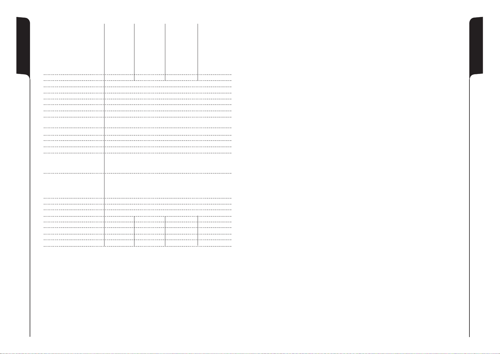
SPECIFICATIONS
HPA 1000 HPA 1400 HPA 2800 HPA 3100L
Max Power Output
STEREO / MONO mode
2ohm --- --- 2 x 1400W 2 x 1700W
4ohm 2 x 510W 2 x 740W 2 x 1050W 2 x 1200W
8ohm 2 x 330W 2 x 440W 2 x 680W 2 x 800W
BRIDGE mode
4ohm --- ---- 1 x 2800W 1 x 3400W
8ohm 1 x 10²⁰W 1 x 1480W 1 x 2100W 1 x 2400W
Amplifier Class Class AB Class H Class H Class HD
Frequency Responce 20Hz to 20KHz +0dB/-0.3dB @8ohm
Distorsion (THD+N) <0,05% @ 1KHz and 1dB below cliping
Intermodulation (SMTE IMD) <0,05% @ 8ohm
Damping Factor >300@1KHz/8ohm >1000@1KHz/8ohm
Slew Rate 50V/uS 55V/uS
Signal To Noise ratio 105dB 105dB 106dB 108dB
Input sensitivity 26dB setting 2,4V 2,8V 3,6V 4,0V
32dB setting 1,2V 1,4V 1,8V 2,0V
Input gain 1,4V setting 30,9dB 32,1dB 34,2dB 35,1dB
Limit switch On/Off
Mode switch Stereo/Bridge/Mono
Input impedance 20Kohm balanced /
REAR PANEL
Input connectors 2 x XLR Female
Link connectors 2 x XLR Male
Output connectors 2 x Speakon
FRONT PANEL for each channel
Level indicators Green LED (from -30dB to 0dB)
Limit indicators Yellow LED
Protection indicators Red LED
Controls volume 41 pos detent
Protections Temperature, DC, RFI, short circuit, Thermal power transformer
Cooling 2 variable - speed fan
Power supply 220-230Vac 50/60Hz
Circuit breaker (Powerswitch) T8A T10A T15A T15A
Rear socket power supply VDE -15A VDE -15A VDE -15A VDE -15A
Dimension (WxDxH) mm 483x400x89 483x400x89 483x400x89 484x431x89
Rack Heigt 2U 2U 2U 2U
Net weight 15,25Kg 17,25Kg 21,35Kg 14Kg
10Kohm unbalanced
27 28
 Loading...