

Page 1
PROFESSIONAL ACTIVE SPEAKERS
A.E.B. INDUSTRIALE s.r.l.
Via Brodolini, 8 - 40056 Crespellano (Bo) - ITALIA
Tel. + 39 051 969870 - Fax. + 39 051 969725
Internet: www.dbtechnologies.com
E-mail: info@dbtechnologies-aeb.com
F15F15
F8F8
MANUALE D’USO
USER MANUAL
BEDIENUNGSANLEITUNG
CARACTERISTIQUES TECHNIQUES
Made in Italy
F212F212
F10F10
COD. 420120139 Rev.2
F315F315
F12F12
RR
digital power
Page 2
FLEXSYS F8 - F10 - F12 - F15FLEXSYS F8 - F10 - F12 - F15
DESCRIZIONE
ItalianoItalianoItaliano
Manuale d’usoManuale d’uso
I diffusori F8, F10, F12 e F15 della serie FLEXSYS utilizzano amplificatori digitali
DIGIPRO di ultima generazione con potenze 200W e 400W per soddisfare qualsiasi tipo
®
di applicazione.
Questi amplificatori, ad alta efficienza, permettono di ottenere elevate potenze di uscita
con pesi e ingombri ridotti. Grazie alla bassa potenza dissipata il raffreddamento del
modulo amplificatore avviene in modo statico, evitando l’uso di ventola.
Il preamplificatore digitale con DSP (Digital Signal Processing) gestisce l’incrocio audio tra
i componenti acustici, la risposta in frequenza, il limiter, e l'allineamento acustico. Un
selettore permette la scelta tra due diverse equalizzazioni, “FLAT” e “PROCESSED“ per
garantire alta versatilità nei diversi utilizzi.
Gli amplificatori DIGIPRO 400W utilizzano alimentatori in tecnologia switching SMPS
®
(Switched-Mode Power Supplies).
Tale tecnologia aumenta l’efficienza, dell’alimentatore e ne diminuisce il peso.
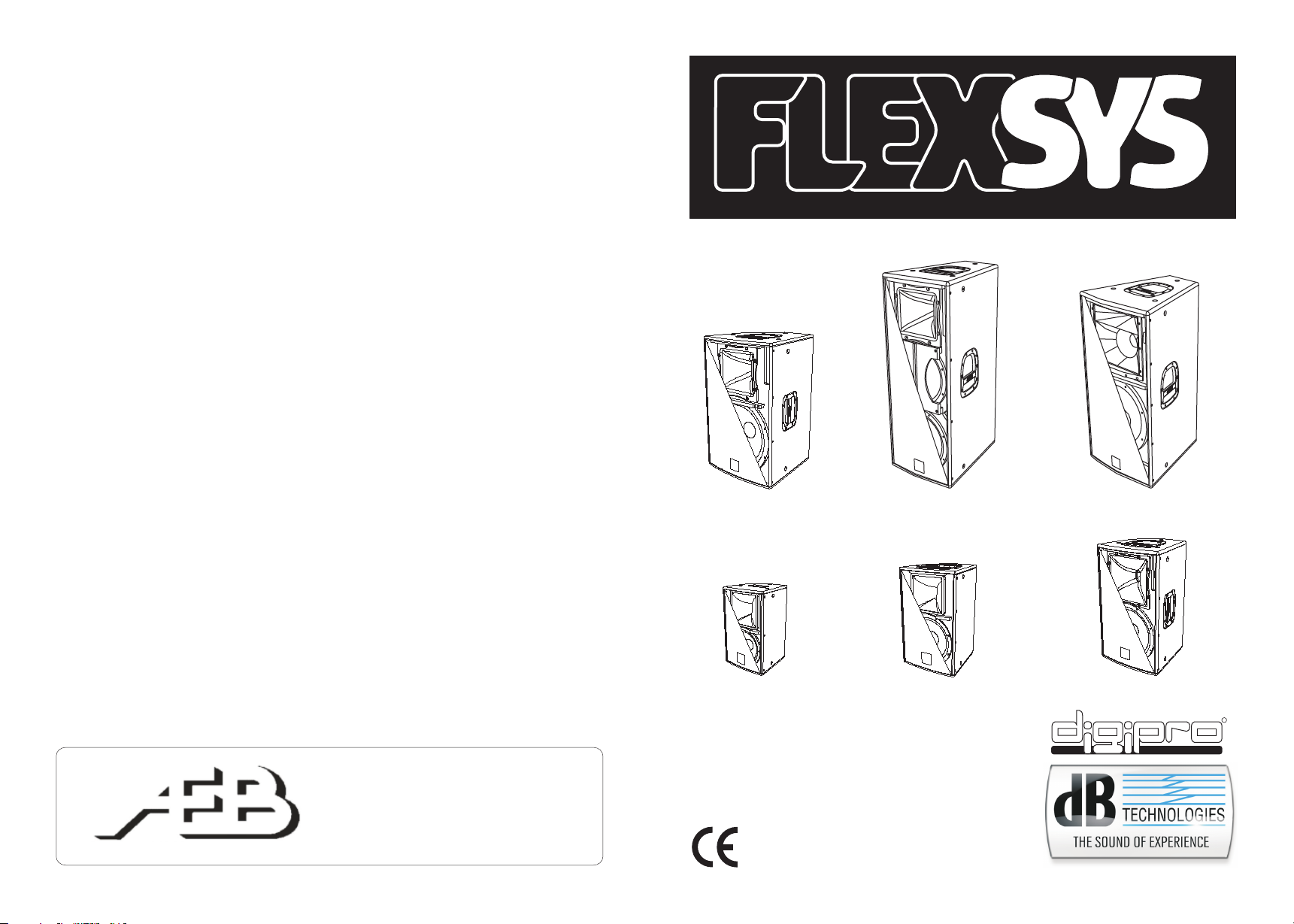
FLEXSYS F8
Il diffusore attivo F8 è equipaggiato con un biamplificatore DIGIPRO in grado di erogare 150W
®
(RMS) per la sezione bassi, e 50W (RMS) per la
sezione alti.
F8 è un diffusore a due vie, con woofer 8” (voice coil
1,5”) e driver al Neodimio da 1” (voice coil 1”) montato
su tromba asimmetrica 90°/40°x60° ruotabile.
Il diffusore è costruito in multistrato con spessore
12mm, 1 maniglia superiore ad incasso e 10 punti M8
posti sui fianchi e sul retro del diffusore ne facilitano
l’installazione e il trasporto.
Il diffusore è stato progettato anche per utilizzocome
stage monitor (con angolazione 40°) ; ruotando la
tromba è possibile mantenere lo stesso angolo di
copertura audio delle alte frequenze.
Nella parte inferiore del box è presente un supporto
piantana standard (D36mm).
FLEXSYS F10
Il diffusore attivo F10 è equipaggiato con un biamplificatore DIGIPRO in grado di erogare 150W
®
(RMS) per la sezione bassi, e 50W (RMS) per la
sezione alti.
F10 è un diffusore a due vie, con woofer 10” (voice coil
2”) e driver al Neodimio da 1” (voice coil 1”) montato su
tromba plastica asimmetrica 90°/40°x60° ruotabile.
Il diffusore è costruito in multistrato con spessore
12mm, 1 maniglia superiore e 12 punti M8 posti sui
fianchi e sul retro del diffusore ne facilitano
l’installazione e il trasporto.
Il diffusore è stato progettato anche per utilizzo come
stage monitor (con angolazione 40°); ruotando la
tromba è possibile mantenere lo stesso angolo di
copertura audio delle alte frequenze.
Nella parte inferiore del box è presente un supporto
piantana standard (D36mm).
FLEXSYS F12
Il diffusore attivo F12 è equipaggiato con un biamplificatore DIGIPRO in grado di erogare 300W
(RMS) per la sezione bassi, e 100W (RMS) per la
sezione alti.
F12 è un diffusore a due vie, con woofer 12” (voice coil
2”) e driver da 1” (voice coil 1,5”) montato su tromba
90°x40° ruotabile.
Il diffusore viene fornito con la tromba orientata a 90°
in senso orizzontale.
Il diffusore è costruito in legno di betulla di spessore
15mm, 3 maniglie e 12 punti M10 posti sui fianchi e sul
retro del diffusore ne facilitano l’installazione e il
trasporto.
Il diffusore è stato progettato anche per utilizzo come
stage monitor (con angolazione 45°); ruotando la
tromba è possibile mantenere lo stesso angolo di
copertura audio delle alte frequenze.
Nella parte inferiore del box è presente un supporto
piantana standard (D36mm).
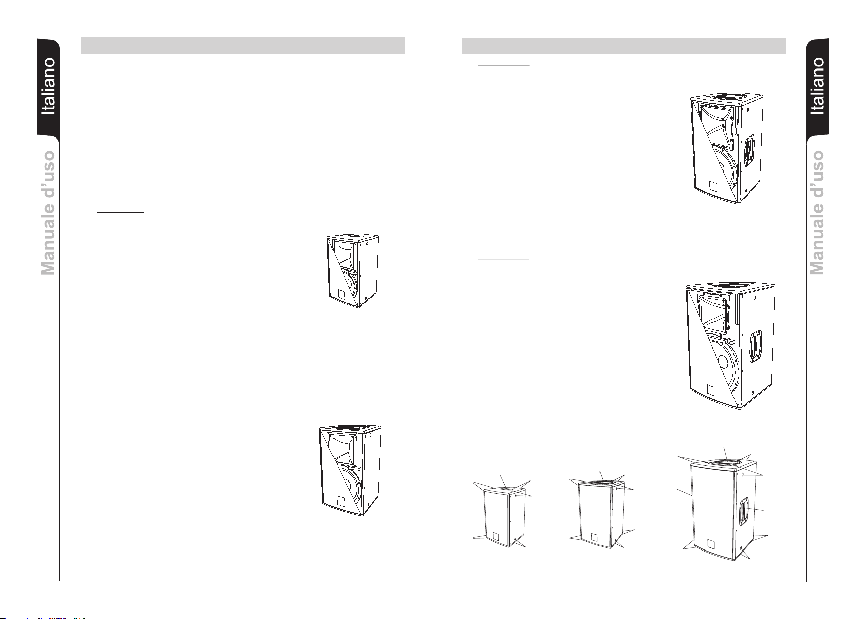
FLEXSYS F15
Il diffusore attivo F15 è equipaggiato con un biamplificatore DIGIPRO in grado di erogare 300W
(RMS) per la sezione bassi, e 100W (RMS) per la
sezione alti.
F15 è un diffusore a due vie, con woofer 15” (voice coil
2”) e driver al Neodimio da 1” (voice coil 1,5”) montato
su tromba 90°x40° ruotabile.
Il diffusore viene fornito com la tromba orientata a 90°
in senso orizzontale.
Il diffusore è costruito in legno di betulla di spessore
15mm, 3 maniglie e 12 punti M12 posti sui fianchi e sul
retro del diffusore ne facilitano l’installazione e il
trasporto.
Il diffusore è stato progettato anche per utilizzo
l’utilizzo come stage monitor (con angolazione 45°) ;
ruotando la tromba è possibile mantenere lo stesso
angolo di copertura audio delle alte frequenze.
Nella parte inferiore del box è presente un supporto
piantana standard (D36mm).
Maniglia
M8
M8
1
F8
FLEXSYS F8 - F10 - F12 - F15FLEXSYS F8 - F10 - F12 - F15
®
®
M8
M8
Maniglia
M8
M8
M8
F10
M8
M8
M8
M8
M10
Maniglia
M10
Maniglia
F12-F15
ItalianoItalianoItaliano
Manuale d’usoManuale d’uso
M10
M10
Maniglia
M10
M10
2
Page 3
FLEXSYS F8 - F10 - F12 - F15FLEXSYS F8 - F10 - F12 - F15 FLEXSYS F8 - F10 - F12 - F15FLEXSYS F8 - F10 - F12 - F15
COMANDI E FUNZIONI
1) CONNETTORI “Balenced Input” - “Link” - “Input- Link”
Questi connettori possono essere utilizzati come ingressi bilanciati per il
collegamento di microfoni bilanciati o sbilanciati o di sorgenti audio a livello linea
ItalianoItalianoItaliano
Manuale d’usoManuale d’uso
(0dB) (es. preamplificatore, mixer, registratore, lettore CD, strumento musicale, ...)
Questi connettori sono collegati in parallelo e possono essere utilizzati per rinviare il
segnale audio ad altri diffusori amplificati, registratori o amplificatori supplementari.
2) INDICATORE LUMINOSO “Ready”
Questo indicatore s'illumina di colore verde per indicare il corretto funzionamento
del diffusore.
Nel normale funzionamento il led è acceso fisso.
3) INDICATORE LUMINOSO “Signal”
Questo indicatore s'illumina di colore verde per indicare la presenza del segnale
audio (ad un livello medio di -20dB).
4) INDICATORE LUMINOSO “Limiter”
Questo indicatore s’illumina di colore rosso per indicare l'intervento del circuito
limitatore interno, il quale evita la distorsione dell'amplificatore e protegge gli
altoparlanti da sovraccarichi.
5) CONTROLLO SENSIBILITA’ INGRESSO “Sensitivity”
Questo controllo regola la sensibilità del segnale in ingresso all’amplificatore.
Tale controllo non influisce sul livello dell’uscita “Link” - “Input - Link”
6) SELETTORE MODE
Questo interruttore a due posizioni permette la selezione tra due diverse
equalizzazioni.
La posizione “Flat” permette di avere una risposta lineare del diffusore perfetta per
l’utilizzo in situazioni “live”.
La posizione “Processed” enfatizza le basse frequenze moderando le medie,
favorendo la riproduzione sonora di brani registrati.
7) SELETTORE SENSIBILITA’ “Input Sens”
Posizionare il selettore in LINE per l’utilizzo di una sorgente a livello linea (0dB) o
MIC per l’utilizzo di un microfono.
8) PRESA DI ALIMENTAZIONE “MAINS ”
Consente la connessione del cavo di alimentazione fornito in dotazione.
9) PORTA FUSIBILE “FUSE”
Alloggio per fusibile di rete.
10) INTERRUTTORE GENERALE “POWER”
L’interruttore permette l’accensione e lo spegnimento del diffusore.
RIFERIMENTO DISEGNI A PAGINE 49 e 50
CARATTERISTICHE E PROTEZIONI
Griglie frontali
Visto l’utilizzo professionale di questi diffusori, i componenti sono protetti frontalmente da
una lamiera forata con spessore 1,2mm e foam interno.
Raffreddamento
Il controllo termico è gestito dal microprocessore interno, che grazie a due sensori
controlla la temperatura dell’amplificatore e dell’alimentatore.Tale controllo agisce
automaticamente sul volume generale.
In caso di surriscaldamento (> 80 gradi) il volume diminuisce in funzione dell’aumento
della temperatura rendendo impercettibile la variazione.
Il corretto volume e tutte le funzioni verranno riprese automaticamente al raggiungimento
delle normali temperature di esercizio.
Accensione
Gli amplificatori sono equipaggiati con un microprocessore per la gestione del DSP,
l’interfaccia utente e il controllo dell’amplificatore.
La regolare accensione del diffusore è garantita da una procedura di inizializzazione;
durante questa fase di test, i LED (”LIMITER”, “SIGNAL” e “READY”), posti sul modulo
amplificatore, rimangono spenti per circa 2 sec.
Al termine della procedura di avvio, sul modulo amplificatore solo il LED verde “READY”
rimane acceso fisso.
Nel caso di un malfunzionamento grave del diffusore, sul modulo amplificatore il LED
rosso “LIMITER” lampeggia e il diffusore viene posto in stato “mute”.
Indicazioni di guasto e protezioni
Il microprocessore è in grado di segnalare tre diversi tipi di guasti tramite diversi lampeggi
del LED rosso “Limiter” prima dell’accensione del LED verde “Ready”
I tre tipi di guasto sono:
1) ATTENZIONE: viene rilevato una errore o un malfunzionamento autoripristinate
non grave e le prestazioni del diffusore non vengono limitate
2) LIMITAZIONE: viene rilevato un errore e vengono limitate le prestazioni del
diffusore (il livello sonoro viene ridotto di 3dB).
Questo stato influisce parzialmente sul funzionamento corretto del diffusore, ed è
comunque necessario contattare il centro assistenza per risolvere il
problema.
3) GUASTO: viene rilevato un malfunzionamento grave. Il diffusore viene posto nello
stato di “mute”.
Lampeggi Indicazione
1 o 2 Attenzione
3 o 4 Limitazione
Da 5 a 8 Guasto
ItalianoItalianoItaliano
Manuale d’usoManuale d’uso
Nel caso di guasto, il LED verde “Ready” rimane spento.
Eseguire le seguenti verifiche:
- Controllare la corretta connessione alla rete d’alimentazione.
- Assicurarsi della corretta tensione d’alimentazione.
- Controllare che l’amplificatore non sia surriscaldato.
- Scollegare dalla rete di alimentazione il diffusore attendere qualche minuto e
riprovare
Se questa segnalazione di errore rimane attiva contattare il centro assistenza autorizzato
3
per risolvere il problema.
4
Page 4

FLEXSYS F212 - F315FLEXSYS F212 - F315
DESCRIZIONE
I diffusori bi-amplificati della serie FLEXSYS sono equipaggiati con amplificatore in classe
D della serie DIGIPRO . Questo amplificatore, ad alta efficienza, permette di ottenere
elevate potenze di uscita con pesi e ingombri ridotti. Grazie alla bassa potenza dissipata il
raffreddamento del modulo amplificatore avviene in modo statico, evitando l’uso di
ItalianoItalianoItaliano
Manuale d’usoManuale d’uso
5
ventola.
Il circuito di alimentazione dell’amplificatore DIGIPRO è stato progettato per funzionare in
modalità full-range; grazie alla tecnologia SMPS (Switched-Mode Power Supplies) con
PFC (Power Factor Correction) viene garantito il funzionamento a tensioni di alimentazioni
da 100Vac a 240Vac, garantendo stesse prestazioni acustiche anche con linee di
alimentazione fluttuanti e non stabilizzate.
FLEXSYS F212 (2 vie)
Il diffusore attivo F212 è equipaggiato con un
amplificatore DIGIPRO in grado di erogare 500W
(RMS) per la sezione bassi e 250W (RMS) per la
sezione alti.
L’ F212 è un diffusore a due vie con due woofer 12”
(voice coil 2,5”) e un compression driver al Neodimio
da 1” (voice coil 1,75”) Il phase plug montato davanti al
cono superiore evita le sovrapposizioni di fase verticali
che normalmente si verificano in questo tipo di
configurazione e garantisce una corretta copertura
orizzontale delle medie frequenze.
Il diffusore è costruito in legno di betulla da 15mm, le 4
maniglie e i 12 punti M10 posti sui fianchi e sul retro del
diffusore ne facilitano l’installazione e il trasporto.
La forma del diffusore trapezoidale (con angolazione
20°) e la tromba con copertura orizzontale di 60 gradi o
ruotata a 40 gradi permette l’accoppiamento laterale
di più diffusori (cluster).
Nella parte inferiore è presente un piede a scomparsa
regolabile per l’inclinazione del diffusore fino a un max
di 5° in appoggio. Questo permette di direzionare
l’angolo di irradiazione sonora senza l’utilizzo di
ulteriori supporti.
Nella parte inferiore del box è presente un supporto
piantana standard (D36mm).
FLEXSYS F315 (3vie)
Il diffusore attivo F315 è equipaggiato con un
amplificatore DIGIPRO in grado di erogare 500W
(RMS) per la sezione bassi, con un woofer 15” (voice
coil 3”), 500W (RMS) per la sezione medio-alti che
attraverso un filtro passivo pilota un midrange 6”(voice
coil 2”) e compression driver da 1” (voice coil 1,5”) .
Il diffusore è costruito in legno di betulla da 15mm, le 4
maniglie e i 12 punti M10 posti sui fianchi e sul retro del
diffusore ne facilitano l’installazione e il trasporto.
Il woofer da 15” e la tromba con copertura orizzontale
di 90 gradi rende questo diffusore ideale per l’utilizzo
full-range .
Nella parte inferiore del box è presente un supporto
piantana standard (D36mm).
®
®
®
®
COMANDI E FUNZIONI
1) CONNETTORE DI INGRESSO " BALANCED INPUT”
Connettore XLR di ingresso bilanciato a livello linea .
2) CONNETTORE DI USCITA "BALANCED LINK/OUT”
Il connettore “XLR” connesso in parallelo con l’ingresso (1) può essere utilizzato per
inviare il segnale audio ad un altro diffusore amplificato.
3) INDICATORE LUMINOSO “LIMITER”
Questo indicatore s’illumina di colore rosso per indicare l'intervento del circuito
limitatore interno, il quale evita la distorsione dell'amplificatore e protegge gli
altoparlanti contro sovraccarichi.
4) INDICATORE LUMINOSO “SIGNAL”
Questo indicatore s'illumina di colore verde per indicare la presenza del segnale
(ad un livello di -20dB).
audio
5) INDICATORE LUMINOSO “MUTE”
Questo indicatore di colore giallo indica lo stato dell’amplificatore.
Nel normale funzionamento il led è spento.
6) INDICATORE LUMINOSO “READY”
Questo indicatore s'illumina di colore verde per indicare che la tensione di
alimentazione di rete è corretta.
Nel normale funzionamento il led è acceso.
7) CONTROLLO SENSIBILITA’ INGRESSO “INPUT SENS”
Questo controllo regola la sensibilità del segnale in ingresso all’amplificatore.
Tale controllo non influisce sul livello dell’uscita “BALANCED LINK/OUT”
FLEXSYS F212
8) SELETTORE “MODE”
Questo interruttore a due posizioni permette la selezione tra due diverse
equalizzazioni.
La posizione “SINGLE SPEAKER” permette di avere una risposta lineare del
diffusore singolo.
La posizione “CLUSTERED SPEAKER” riduce la quantità di frequenze medio basse
che vengono generate dall’accoppiamento di più diffusori affiancati.
9) PRESA DI ALIMENTAZIONE “MAINS INPUT”
Consente la connessione del cavo di alimentazione.
Il connettore utilizzato per il collegamento alla rete è un POWER CON® (blu)
10) PRESA DI ALIMENTAZIONE RILANCIO “MAINS OUTPUT LINK”
Consente di rilanciare l’alimentazione di rete. L’uscita è connessa in parallelo con
l’ingresso (9) e può essere utilizzata per alimentare un altro diffusore amplificato.
Il connettore utilizzato è un POWER CON® (grigio).
11) PORTA FUSIBILE “MAINS FUSE”
Alloggio per fusibile di rete.
FLEXSYS F315
8) SELETTORE “MODE”
Questo interruttore a due posizioni permette la selezione tra due diverse
equalizzazioni.
La posizione “FLAT” permette di avere una risposta lineare del diffusore, adatta
soprattutto per l’utilizzo “live” in locali chiusi.
La posizione “PROCESSED” aumenta le frequenze basse ed è adatto per musica
riprodotta o per l’utilizzo all’aperto.
9) PRESA DI ALIMENTAZIONE “MAINS INPUT”
Consente la connessione del cavo di alimentazione.
10) PORTA FUSIBILE “MAINS FUSE”
Alloggio per fusibile di rete.
11) INTERRUTTORE GENERALE “POWER”
L’interruttore permette l’accensione e lo spegnimento del diffusore.
RIFERIMENTO DISEGNI A PAGINE 51 e 52
FLEXSYS F212 - F315FLEXSYS F212 - F315
ItalianoItalianoItaliano
Manuale d’usoManuale d’uso
6
Page 5

FLEXSYS F212 - F315FLEXSYS F212 - F315
CARATTERISTICHE
Griglie frontali
Visto l’utilizzo professionale di questi diffusori, i componenti sono protetti frontalmente da
una lamiera forata con spessore 1,5mm e foam interno.
Raffreddamento
ItalianoItalianoItaliano
Manuale d’usoManuale d’uso
Il raffreddamento dell’amplificatore avviene attraverso il pannello in alluminio posto sul
retro del diffusore stesso.
La protezione termica è garantita da un circuito interno che controlla la temperatura
dell’amplificatore stesso e lo protegge dal surriscaldamento limitando il volume generale
(con temperatura >80°).
Se la temperatura raggiunge quella massima di utilizzo (>80°), il segnale audio viene posto
in stato di “mute” e verrà segnalato tramite l’accensione dell’indicatore luminoso giallo
“MUTE”.
Il corretto volume e tutte le funzioni verranno riprese automaticamente al raggiungimento
delle normali temperature di esercizio.
Protezione
L’accensione dell’indicatore luminoso giallo “MUTE” indica che l’amplificatore ha rilevato
un malfunzionamento sul diffusore, ponendolo in stato di mute.
Eseguire le seguenti verifiche:
- Controllare la corretta connessione alla rete d’alimentazione.
- Assicurarsi della corretta tensione d’alimentazione.
- Controllare che l’amplificatore non sia surriscaldato.
- Scollegare dalla rete di alimentazione il diffusore ed attendere qualche minuto e
riprovare
Se dopo tale prove l’indicatore non si spenge contattare un centro assistenza autorizzato.
COLLEGAMENTI (solo per FLEXSYS F212)
Collegamento alla alimentazione di rete
Ogni diffusore attivo è provvisto del proprio cavo di alimentazione. Il collegamento
avviene tramite un connettore modello Neutrik POWER CON® (blu) che permette di
avere una facile e rapita connessione al diffusore oltre che a un ottimo sistema di
bloccaggio.
Lo stesso connettore serve da interruttore per accendere e spegnare il diffusore.
L’apparecchio dovrà essere collegato ad una rete di alimentazione che possa erogare la
massima potenza richiesta.
Rilancio alimentazione di rete
Sul retro del diffusore è presente un connettore Neutrik POWER CON® (grigio) per il
rilancio di alimentazione di rete.
Questa presa ha lo scopo di rilanciare l’alimentazione ad un altro diffusore riducendo i
collegamenti diretti alla rete. Gli assorbimenti massimi degli amplificatori sono riportati sul
pannello dell’amplificatore.
Il numero massimo dei diffusori collegati insieme varia sia per gli assorbimenti massimi
dei diffusori e sia dalla corrente massima della prima presa di alimentazione.
FLEXSYS F8 - F10 - F12 - F15 - F212 - F315FLEXSYS F8 - F10 - F12 - F15 - F212 - F315
ROTAZIONE TROMBA (escluso FLESYS F315)
Il diffusore permette di modificare l’angolo di copertura, tramite la rotazione della tromba.
Il diffusore viene fornito dalla ditta costruttrice sempre con la tromba orientata
senso orizzontale per i diffusori Flexsys F8, F10, F12 e F15 mentre a 60°in senso
orizzontale per il diffusore Flexsys F212.
Solo il modello Flexsys F212 può essere utilizzato affiancando più diffusori (cluster), in
questo caso occorre ruotare la tromba.
Se si desidera modificare l’angolo di copertura della tromba è necessario (Fig. 5):
- svitare le viti di fissaggio della rete
- rimuovere la rete di protezione anteriore esercitando una leggera pressione su un
lato e sollevarla dall’opposito incasso
- svitare le otto viti di fissaggio della tromba
- ruotare la tromba nella posizione desiderata (non estrarre mai il blocco tromba dal
diffusore)
- rinvitare le viti di fissaggio della tromba
- inserire nuovamente la rete negli appositi incassi laterali e rinvitare le viti della rete.
INSTALLAZIONE DEL DIFFUSORE
ATTENZIONE
Installare il diffusore in modo stabile e sicuro, così da evitare qualsiasi condizione di
pericolo per l’incolumità di persone e strutture.
Per evitare condizioni di pericolo non sovrapporre fra loro più diffusori senza adeguati
sistemi di ancoraggio. Prima si sospendere il diffusore controllare tutti i componenti da
utilizzare, che non devono presentare danni, deformazioni, parti mancanti o danneggiate
che possono ridurre la sicurezza dell’installazione.
Nell’utilizzo all’aperto evitare luoghi esposti alle intemperie.
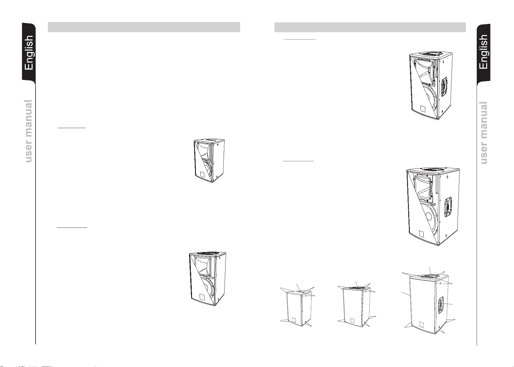
Il diffusore viene fornito dalla ditta costruttrice predisposto per l’utilizzo :
- in appoggio (Fig. 1)
- a pavimento (come monitor) (Fig. 2) solo FLEXSYS F8,F10,F12 e F15
- su supporto piantana (Fig.3)
- appeso con golfari o apposite staffe fornite dalla ditta (Fig.4)
ATTENZIONE
Non utilizzare mai le maniglie per appendere il diffusore!
ATTENZIONE
Per appendere il diffusore utilizzare solo una vite per ogni punto di appendibilità
I punti di appendibilità sono di 8MA nei modelli Flexsys F8, F10 e di 10MA nei
modelli Flexsys F12, F15, F212 e F315.
a 90° in
ItalianoItalianoItaliano
Manuale d’usoManuale d’uso
CLASSIFICAZIONE EMI
7
In accordo alle normative EN 55103, l'apparato è progettato e idoneo all'utilizzo in ambienti
Elettromagnetici E3 o inferiori (E2, E1).
SBAGLIATO! CORRETTO!
CORRETTO!
8
Page 6

ItalianoItalianoItaliano
ItalianoItalianoItaliano
Manuale d’usoManuale d’uso
47-20000Hz (-10dB)
2000Hz - 18dB/oct passivo
1x1”compression driver - 1,5” voice coil
Manuale d’usoManuale d’uso
Sbilanciato 10Kohm Sbilanciato 10Kohm
FLEXSYS F8 FLEXSYS F10 FLEXSYS F12
75-20000Hz (-10dB) 70-20000Hz (-10dB) 65-20000Hz (-10dB)
1x1” compression driver - 1” voice coil 1x1” compression driver - 1” voice coil 1x1” compression driver - 1.5” voice coil
220-240Vac 50-60Hz 220-240Vac 50-60Hz 220-240Vac 50-60Hz
1 ad incasso sopra 1 in plastica sopra 1 in plastica sopra
--- --- ---
FLEXSYS F15 FLEXSYS F212 FLEXSYS F315
55-20000Hz (-10dB) 50-20000Hz (-10dB)
1800Hz, 24dB/oct 1800Hz - 24dB/oct
1x1” compression driver - 1.5” voice coil 1x1” compression driver - 1,75” voice coil 1x6.5” midrange - 2” voice coil
-3dBu Max
220-240Vac 50-60Hz 100-240Vac 50-60Hz 100-240Vac 50-60Hz
2K2ohm/20Kohm (MIC/LINE)
1 in plastica sopra 1 in plastica sopra 1 in plastica sopra
---------- 1 ad incasso parte bassa 1 ad incasso parte bassa
Neodimio Neodimio
9
Sistema Attivo Biamplificato Attivo Biamplificato Attivo Biamplificato
Tipologia amplificatore Classe D Classe D Classe D
Potenza RMS 150W + 50W 150W + 50W 300W +100W
Risposta in frequenza 90-19000Hz (+/-3dB) 80-19000Hz (+/-3dB) 75-19000Hz (+/-3dB)
Crossover 2050Hz , 24dB/oct 2050Hz , 24dB/oct 1800Hz, 24dB/oct
Pressione sonora (max SPL) 121dB 125dB 127dB
Componenti 1x8” woofer - 1.5” voice coil 1x10” woofer - 2” voice coil 1x12” woofer - 2” voice coil
Dispersione 90°/40°x60° Asimmetrica 90°/40°x60° Asimmetrica 90°x40°
Sensibilità ingresso -3dBu Max -3dBu Max -3dBu Max
Impedenza ingresso 2K2ohm/20Kohm (MIC/LINE) 2K2ohm/20Kohm (MIC/LINE) 2K2ohm/20Kohm (MIC/LINE)
Alimentazione 110-120Vac 50-60Hz 110-120Vac 50-60Hz 110-120Vac 50-60Hz
Forma diffusore Trapezioidale Trapezioidale Trapezioidale
Colore diffusore Nero Nero Nero
Dimensioni (WxHxD) 260x420x260mm 300x480x300mm 360x610x360mm
Peso 9,5Kg 12Kg 16.5Kg
Inserti per appendibilità 10 punti x M8 12 punti x M8 12 punti x M10
Supporto piantana D36mm D36mm D36mm
Maniglie --- ---- 2 in plastica ai lati
Tromba ruotabile Si Si Si
Piede regolabile No No No
DATI TECNICI
Sistema Attivo Biamplificato Attivo Biamplificato Attivo Biamplificato
Tipologia amplificatore Classe D Classe D Classe D
Potenza RMS 300W + 100W 500W +2 50W 500w + 500W
Risposta in frequenza 60-19000Hz (+/-3dB) 65-19000Hz (+/-3dB) 60-19000Hz (-3dB)
Crossover 750Hz - 24dB/oct
Pressione sonora (max SPL) 128dB 132dB 131dB
Componenti 1x15” woofer - 2” voice coil 2x12” woofer - 2,5” voice coil 1x15” woofer - 3” voice coil
Dispersione 90°x40° 60°x40° 90°x40°
Sensibilità ingresso -3dBu Max -3dBu Max
Impedenza ingresso Bilanciato 20Kohm Bilanciato 20Kohm
Alimentazione 110-120Vac 50-60Hz Full-range con PFC Full-range con PFC
Forma diffusore Trapezioidale Trapezioidale Trapezioidale
Colore diffusore Nero Nero Nero
Dimensioni (WxHxD) 430x680x430mm 300x480x300mm 440x880x500mm
Peso 20Kg 31,5Kg 31 Kg
Inserti per appendibilità 12 punti x M10 12 punti x M10 12 punti x M10
Supporto piantana D36mm D36mm D36mm
Maniglie 2 in plastica ai lati 2 in plastica ai lato 2 in plastica ai lati
Tromba ruotabile Si Si No
DATI TECNICI
10
Piede regolabile No Si No
Page 7
11
EnglishEnglishEnglish
user manualuser manual
FLEXSYS F8 - F10 - F12 - F15FLEXSYS F8 - F10 - F12 - F15
DESCRIPION
The speakers F8. F10, F12 and F15 of FLEXSYS series use cutting edge digital
amplifiers of the DIGIPRO series, providing with powers 200W and 400W to meet the
requirements of any kind of application.
These highly efficient amplifiers provide high power with limited weight and dimension.
Thanks to the low power dissipated, the cooling of the amplifier module does not require a
fan.
The digital preamplifier with DSP (Digital Signal Processing) controls the audio crossover
between the acoustic components, the frequency response, the limiter, and the acoustic
alignment. A selector enables to select one of two different equalizations - “FLAT” or
“PROCESSED“ - to provide high versatility for the different applications.
The amplifiers DIGIPRO 400W use power supplies featuring SMPS (Switched-Mode
Power Supplies) technology.
This technology increases power supply efficiency and minimizes its weight.
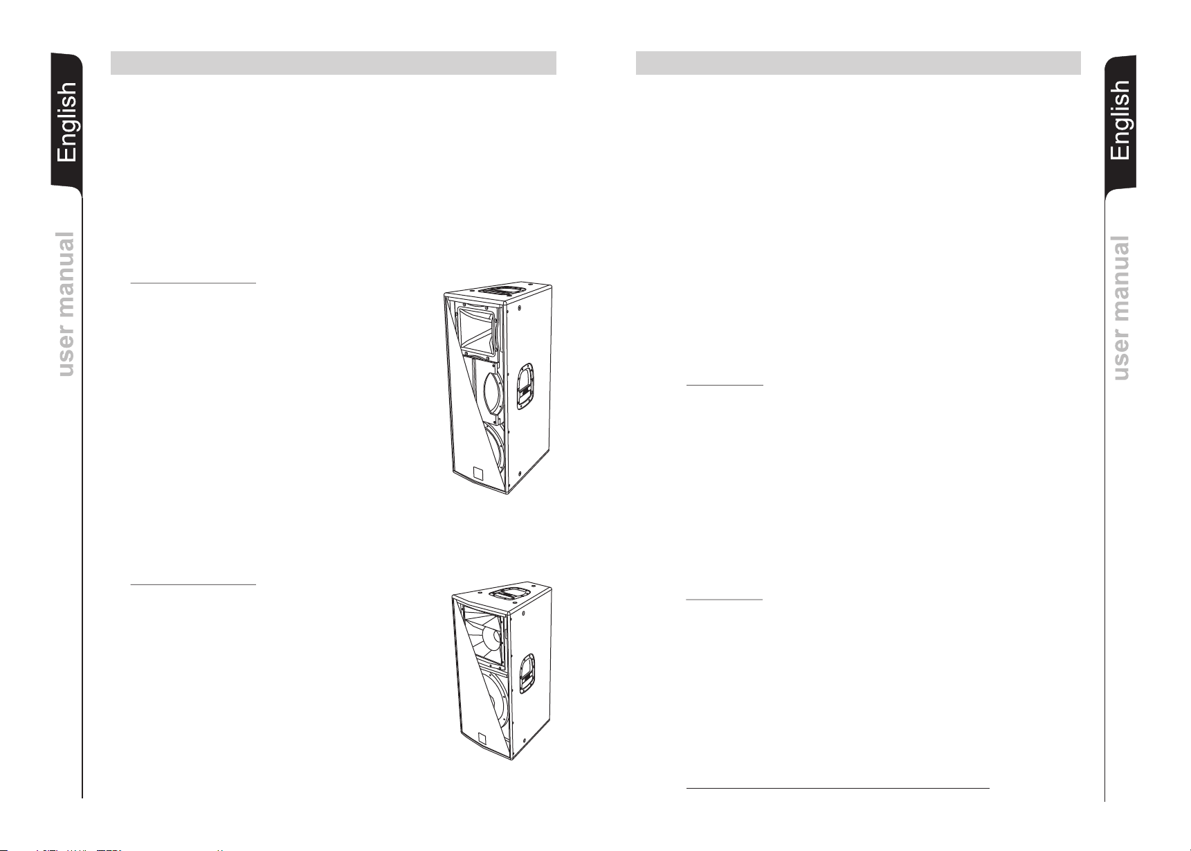
FLEXSYS F8
The F8 bi-amped active speaker is equipped with a
DIGIPRO amplifier delivering 150W RMS for the bass
®
section and 50W RMS for the high frequency section.
F8 active two-way speaker features woofer 8” (voice
coil 1,5”) and a neodymium compression driver 1”
(voice coil 1”) on a 90°/40°x 60° asymmetrical horn.
The speaker is made of 12mm ply wood, the one top
handle the 10 M8 threads located on the
housing and
sides and the back of the speaker are enabling easy
transport and installation.
The speaker has been designed to be used also as
stage monitor (40° angle), by rotating the horn you can
maintain the same audio coverage angle of high
frequencies also when the speaker is used as monitor.
In the bottom of the box there is a standard pole mount
cup (D36mm).
FLEXSYS F10
F10 bi-amped active speaker is equipped with a
DIGIPRO amplifier delivering 150W RMS for the bass
®
section and 50W RMS for the high frequency section.
F10 active two-way speaker features a woofer 10”
(voice coil 2”) and a neodymium compression driver 1”
(voice coil 1”) on a 90°/40°x 60° asymmetrical horn.
The speaker is made of 12mm plywood, the one top
plastic handle and the 12 M8 threads located on the
sides and the back of the speaker are enabling easy
transport and installation.
The speaker has been designed to be used also as
stage monitor (40° angle), by rotating the horn you can
maintain the same audio coverage angle of high
frequencies also when the speaker is used as monitor.
In the bottom of the box there is a standard pole mount
cup (D36mm).
®
®
FLEXSYS F8 - F10 - F12 - F15FLEXSYS F8 - F10 - F12 - F15
FLEXSYS F12
The F12 bi-amped active speaker is equipped with a
DIGIPRO amplifier delivering 300W RMS for the bass
section and 100W RMS for the high frequency
section.
F12 active two-way speaker features woofer 12”
(voice coil 1”) and compression driver 1” (voice coil
1,5”) on a 90°x40° CD- horn.
The speakers’ horizontal directivity is 90° by default
factory setting.
The speaker is made of 15mm birch plywood, the
three plastic handles the 12 M10 threads located
on the sides and the back of the speaker are enabling
easy transport and installation.
The speaker has been designed to be used also as
stage monitor (45° angle), by rotating the horn you can
maintain the same audio coverage angle of high
frequencies also when the speaker is used as
monitor.
In the bottom of the box there is a standard pole mount
cup (D36mm).
FLEXSYS F15
F15 bi-amped active speaker is equipped with a
DIGIPRO amplifier delivering 300W RMS for the bass
section and 100W RMS for the high frequency
section.
F15 active two-way speaker features a woofer 15”
(voice coil 2”) and a neodymium compression driver 1”
(voice coil 1,5”) on a 90°x40° CD- horn.
The speakers’ horizontal directivity is 90° by default
factory setting.
The speaker is made of 15mm birch plywood, the
three plastic handles and the 12 M10 threads located
on the sides and the back of the speaker are enabling
easy transport and installation.
The speaker has been designed to be used also as
stage monitor (45° angle), by rotating the horn you can
maintain the same audio coverage angle of high
frequencies also when the speaker is used as monitor.
In the bottom of the box there is a standard pole mount
cup (D36mm).
M8
M8
Handle
F8
®
and
®
M8
M8
Handle
M8
M8
M8
M8
M8
M8
F10
M8
M10
Handle
M10
Handle
F12-F15
M10
M10
EnglishEnglishEnglish
user manualuser manual
M10
Handle
M10
12
Page 8
FLEXSYS F8 - F10 - F12 - F15FLEXSYS F8 - F10 - F12 - F15
FLEXSYS F8 - F10 - F12 - F15FLEXSYS F8 - F10 - F12 - F15
COMMANDS AND FUNCTIONS
AMPLIFIER PANEL
1) “Balenced Input” - “Link” - “Input Link” CONNECTORS
These balanced inputs can be used to connect balanced or unbalanced
EnglishEnglishEnglish
user manualuser manual
microphones or audio sources at line level (0dB) (eg. preamplifier, mixer,
recorder, CD player, musical instrument, ...).
The balanced connector is connected in parallel and can be used to send the
audio signal to other amplified speakers, recorders or supplementary amplifiers.
2) “Ready” INDICATOR LIGHT
This indicator shows green to indicate that the main power voltage is correct.
The LED shows green normal operating conditions.
3) “Signal” INDICATOR LIGHT
This indicator shows green to indicate the presence of the audio signal (at a level of
-20dB).
4) “Limiter” INDICATOR LIGHT
This indicator shows red to indicate that the internal limiter circuit has tripped.
This prevents amplifier distortion and protects the speakers against overloads.
5) “Sensitivity” INPUT SENSITIVITY CONTROL
This control adjusts the sensitivity of the signal amplifier input.
This control does not affect the “Link” - “Input - Link” output level
6) MODE SWITCH
This two-way switch allows to choose between two different system presets.
The “Flat” position allows linear response of the speaker, which is mainly suitable
for the “live” application.
The “Processed” position emphasizes the low frequency and regulates the mid
frequency. It is suitable for music play back
7) “Input Sens” SWITCH
Position the switch in LINE to use a line level source (0 dB) or MIC to use a
microphone.
8) POWER CABLE SOCKET “MAINS”
Used for connecting the power cable supplied.
9) FUSE CARRIER “FUSE”
Mains fuse housing.
10) POWER SWITCH “POWER”
This switch can be used to switch the diffuser on and off.
REFERENCE DRAWINGS AT PAGES 49 and 50
CHARACTERISTICS AND PROTECTION
Front Grille
The speakers’s components in the box are protected by 1.2mm metal steel grille covered
by foam on backside.
Cooling
Thermal control is provided by the internal microprocessor which, by means of two
sensors, controls the temperature of the amplifier and of the power supply, avoiding
overheating by limiting the overall volume.
In case of overheating (> 80 degrees) the volume decreases proportionally to the
temperature increase, making the change unnoticeable.
The correct volume and all the functions are automatically restored when standard
operating temperatures are reached.
Switch on
The amplifiers are equipped with a microprocessor to control the DSP and the amplifier.
The correct switch on of the amplifier is ensured by an initialization procedure; during this
test stage, the blue front LED flashes twice and the LEDs ( Limiter , Signal and Ready ),
located on the amplifier module, remain off for approx. 2 sec.
At the end of the switch on procedure, the front LED lights up (if enabled) and on the
amplifier module the Ready green LED only remains steadily on.
In case of severe failure of the speaker, the LED on the front panel flashes several times
and on the amplifier module, the Limiter red LED flashes and the speaker switches to
“mute”.
Failure indications and safeties
The microprocessor is able to signal three different kinds of failure by flashing the “Limter”
red LED on the amplifier panel before the lighting up of the “Ready” green LED. The three
types of failure are:
1) WARNING: a non severe error or auto-ripristinate malfunction is detected and the
performance of the speaker is not limited
2) LIMITATION: an error is detected and the performance of the speaker is limited (the
sound level is reduced by 3dB).
This does not affect the operation of the speaker since it continues to operate.
However, it is necessary to call the service centre to solve the issue.
3) FAILURE: a severe malfunction is detected. The speaker switches to “mute”.
Flashing Indication
1 or 2 Warning
3 or 4 Limitation
from 5 to 8 Failure
“”
“”
“”“” “”
EnglishEnglishEnglish
user manualuser manual
13
In case of failure, the “Ready” green LED remains off.
Perform the checks listed below:
- Check if the speaker is properly connected to the power supply.
- Make sure that the power supply is of correct voltage.
- Check that the amplifier is not overheated.
- Disconnect the speaker from the mains power supply, wait for a few minutes and
connect it again.
If after these tests the red “LIMITER” LED is still on, please contact an authorised service
centre.
14
Page 9
FLEXSYS F212 - F315FLEXSYS F212 - F315
FLEXSYS F212 - F315FLEXSYS F212 - F315
DESCRIPTION
EnglishEnglishEnglish
user manualuser manual
The FLEXSYS series bi-amped speakers are equipped with
DIGIPRO series class D amplifier. This high-efficiency
amplifier delivers high output power in a compact size at low
weight. Thanks to its high efficiency the cooling of the
amplifier module is obtained statically, thus avoiding the use
of a fan.
The power supply circuits of the DIGIPRO amplifier has
been conceived to work in full-range mode; thanks to the
SMPS (Switched-Mode Power Supply) technology with PFC
(Power Factor Correction) the operation with supply voltages
between 100 Vac and 240Vac is guaranteed by ensuring the
same sound performances even with floating and nonstabilized power supply systems.
FLEXSYS F212 (2 ways)
The F212 bi-amped active speaker is equipped with a
DIGIPRO amplifier which delivers 500W RMS for the bass
section and 250W RMS for the high frequency section.
The F212 active two-way speaker features two 12” (voice coil
2.5”) woofers and a neodymium 1”(voice coil 1.75”)
compression driver. The phase plug attached to the front of
the upper 12” woofer avoids the vertical phase modulation
which usually take place in this type of configuration and
ensures a precise horizontal coverage of the medium
frequencies.
The speaker is made of 15mm birch ply wood, the 4 handles,
the 12 M10 threads located on the sides and the back of the
speaker are enabling easy transport and installation.
The trapezoidal-shaped housing (20° angle) allows the sideby-side setup of several speakers in cluster configuration. For
side-by-side installation, the horn must be turned (40° x 60°)!
The bottom features a adjustable foot (in height) to inclinate
the tilt angle up to a max. of 5°. This allows to direct the sound
radiation without using additional supports.
In the bottom of the box there is a standard pole mount cup
(D36mm) made of aluminium
FLEXSYS F315 (3 ways)
The F315 active speaker is equipped with a DIGIPRO
amplifier delivering 500W RMS for the bass section featuring
a 15” woofer (voice coil 3”) and 500W RMS for the mid-high
section featuring a passive filter driving a 6” midrange (voice
coil 2”) and a 1” compression driver (voice coil 1.5”).
The speaker is made of 15mm birch ply wood, the 4 handles,
the 12 M10 threads located on the sides and the back of the
speaker are enabling easy transport and installation
The 15” woofer and the midh-high section with horizontal 90°
coverage is the ideal solution for all demanding full-range
applications .
In the bottom of the box there is a standard pole mount cup
(D36mm) made of aluminium
®
®
®
®
CONTROLS AND FUNCTIONS
1) " BALANCED INPUT” INPUT CONNECTOR
Balanced input at line level. Accepts “XLR” sockets.
2) "BALANCED LINK/OUT ” OUTPUT CONNECTOR
The “XLR” connector connected in parallel with input (1) can be used to send the
input audio signal to another active speaker.
3) “LIMITER” INDICATOR LIGHT
This indicator shows red to indicate that the internal limiter circuit has tripped.
This prevents amplifier distortion and protects the speakers against overloads.
4) “SIGNAL” INDICATOR LIGHT
This indicator showscomes on green to indicate the presence of the audio signal (at
a level of -20dB).
5) “MUTE” INDICATOR LIGHT
This yellow indicator indicates amplifier status.
The LED is off in normal operating conditions.
6) “READY” INDICATOR LIGHT
This indicator shows green to indicate that the main power voltage is correct.
The LED shows green in normal operating conditions
7) “INPUT SENS” INPUT SENSITIVITY CONTROL
This control adjusts the sensitivity of the signal amplifier input.
This control does not affect the “BALANCED LINK/OUT” output level
FLEXSYS F212
8) "MODE" SWITCH
This two-way switch allow to choose between two different system presets.
The “SINGLE SPEAKER” position allows linear response when one single speaker
is used.
The “CLUSTERED SPEAKER” position reduces the medium-bass frequencies
which are coupling by the side-by-side attachment of several speakers.
9) "MAINS INPUT" POWER SOCKET
For connecting the power cable provided.
The connector used for mains connection is a POWER CON® (blue) socket
10) “MAINS OUTPUT LINK” POWER SOCKET
For linking the mains power. The output is connected in parallel with input (9) and
can be used to power another active speaker.
The connector is a POWER CON® (grey) socket
11) "MAINS FUSE" FUSE CARRIER
Mains fuse housing.
FLEXSYS F315
8) "MODE" SWITCH
This two-way switch allows to choose between two different system presets.
The “FLAT” position allows linear response of the speaker, which is mainly suitable
for the “live” application in closed rooms.
The “PROCESSED” position increases the low frequencies and it is suitable for
music play back or for the use in open air applications.
9) POWER CABLE SOCKET “MAINS INPUT”
Used for connecting the power cable supplied.
10) FUSE CARRIER “MAINS FUSE”
Mains fuse housing.
11) POWER SWITCH “POWER”
Switches the active speaker on and off.
EnglishEnglishEnglish
user manualuser manual
15
REFERENCE DRAWINGS AT PAGES 51 and 52
16
Page 10

CHARACTERISTICS
Front Grille
The speakers’s components in the buffle are protected by 1.5mm metal steel grille
covered by foam on backside.
EnglishEnglishEnglish
Cooling
The amplifier is cooled by means of the aluminium panel placed on the back of the
speaker.
The thermal protection is ensured by an internal circuit which controls the temperature of
the amplifier and protects this against any risk of overheating thus limiting the general
volume ( temperature >80°C).
If the temperature reaches the maximum operating temperature (>80°C), the audio signal
is set to the “MUTE” position and it will be indicated by the switching on of the yellow
“MUTE” LED.
The requiriered volume and all functions will be restored automatically when the normal
operating temperatures are reached.
Protection
When the yellow “MUTE” LED turns on, it means that a malfunction has been detected on
the speaker, thus setting this to the mute position.
user manualuser manual
Perform the checks listed below:
- Check if the speaker is properly connected to the power supply.
- Make sure that the power supply is of correct voltage.
- Check that the amplifier is not overheated.
- Disconnect the speaker from the mains power supply, wait for a few minutes and
connect it again.
If after these tests the yellow “MUTE” LED is still on, please contact an authorised service
centre.
FLEXSYS F212 - F315FLEXSYS F212 - F315
FLEXSYS F8 - F10 - F12 - F15 - F212 - F315FLEXSYS F8 - F10 - F12 - F15 - F212 - F315
ROTATING HORN (Except FLEXSYS F315)
Loudspeaker allows to maintain the same coverage angle by featuring a rotating horn.
The speakers are always supplied by the manufacturer with the horn positioned horizontal
by default at 90° for Flexsys F8, F10, F12 and F15 and 60° by default for F212.
Only Flexsys F212 can be used placing more speakers side by side (cluster), in this case is
necessary rotate the horn.
If you wish to change the coverage angle (Fig. 5):
- unscrew the fixing screws of the grille
- remove the front protective grille by slightly pressing on one side and taking the grille
off the recessed slots
- unscrew the fixing screws of the horn
- rotate the horn in the desired position (the horn should never be removed from the
driver!)
- tighten the fixing screws of the horn
- put the grille back in the recessed slots and tighten the screws of the grille.
LOUDSPEAKER INSTALLATION
WARNING
Make sure that the loudspeaker is securely installed in a stable position to avoid any
injuries or damages to persons or property.
For safety reasons do not place one loudspeaker on top of another without proper fastening
systems. Before hanging the loudspeaker check all the components for damages,
deformations, missing or damaged parts that may compromise safety during installation.
If you use the loudspeakers outdoors avoid places that are exposed to bad weather.
The loudspeaker has the following mounting options:
- bookshelf (Fig. 1)
- floor (monitor) (Fig.2)
- on speaker stands (Fig.3)
- suspended with support rails or brackets supplied by the manufacturer (Fig.4)
EnglishEnglishEnglish
user manualuser manual
17
CONNECTIONS (Only for FLEXSYS F212)
Connecting to the mains supply
Each active speaker features its own power cable. Connection is done by a Neutrik
POWER CON® (blue) model which permits easy and fast connection to the speaker as
well as being an excellent locking system.
The same connector serves as a switch to turn ON and OFF the active loudspeaker by
turning the connector to the left (OFF) or right (ON).
The active speaker must be connected to a power supply able to deliver the maximum
required power.
Main power supply linking
On the rear of the speaker, a Neutrik POWER CON® connector (grey) offers linking the
mains power supply.
This socket links the power supply to another speaker, thereby reducing the direct
connections to the mains. Maximum amplifier input power is shown on the amplifier
panel.
The maximum number of speakers connected together varies of max input power and
of the maximum allowed current of the first power socket.
EMI CLASSIFICATION
According to the standards EN 55103 this equipment is designed and suitable to operate in
E3 (or lower E2, E1) Electromagnetic environments.
WARNING
Never use the handles to hang the speaker!
WARNING
To hang the loudspeaker use only one eyebolt for each hanging point
The hanging points are of M8 threads for Flexsys F8,F10 and M10 threads for
Flexsys F12, F15, F212 and F315.
Do not unscrew both bolts recessed in the housing!
WRONG! EXACT!
EXACT!
18
Page 11

EnglishEnglishEnglish
EnglishEnglishEnglish
47-20000Hz (-10dB)
2000Hz - 18dB/oct passive
user manualuser manual
0Hz , 24dB/oct 2050Hz , 24dB/oct 1800Hz, 24dB/oct
FLEXSYS F8 FLEXSYS F10 FLEXSYS F12
5-20000Hz (-10dB) 70-20000Hz (-10dB) 65-20000Hz (-10dB)
150W + 50W 150W + 50W 300W +100W
7
121dB 125dB 127dB
1x1” compression driver - 1” voice coil 1x1” compression driver - 1” voice coil 1x1” compression driver - 1.5” voice coil
-3dBu Max -3dBu Max -3dBu Max
2K2ohm/20Kohm (MIC/LINE) 2K2ohm/20Kohm (MIC/LINE) 2K2ohm/20Kohm(MIC/LINE)
220-240Vac 50-60Hz 220-240Vac 50-60Hz 220-240Vac 50-60Hz
1 top side,niche 1 top side 1 top side
--- --- ---
No No No
FLEXSYS F15 FLEXSYS F212 FLEXSYS F315
55-20000Hz (-10dB) 50-20000Hz (-10dB)
300W + 100W 500W +2 50W 500w + 500W
1800Hz, 24dB/oct 1800Hz - 24dB/oct
60-19000Hz (+/-3dB) 65-19000Hz (+/-3dB) 60-19000Hz (-3dB)
1x1”compression driver - 1,5” voice coil
user manualuser manual
Unbalanced 10Kohm Unbalanced 10Kohm
-3dBu Max
128dB 132dB 131dB
1x1” compression driver - 1.5” voice coil 1x1” compression driver - 1,75” voice coil 1x6.5” midrange - 2” voice coil
2K2ohm/20Kohm (MIC/LINE)
220-240Vac 50-60Hz 100-240Vac 50-60Hz 100-240Vac 50-60Hz
1 top side 1 top side 1 top side
---------- 1 back side,niche 1 back side,niche
19
90-19000Hz (+/-3dB) 80-19000Hz (+/-3dB) 75-19000Hz (+/-3dB)
Neodimium Neodimium
RMS power
System Active Bi-Amp Active Bi-Amp Active Bi-Amp
TECHNICAL SPECIFICATIONS
Frequency response
Type of amplifier Class D Class D Class D
Sound pressure (max SPL)
Crossover 205
Components 1x8” woofer - 1.5” voice coil 1x10” woofer - 2” voice coil 1x12” woofer - 2” voice coil
Dispersion 90°/40°x60° Asymmetrical 90°/40°x60° Asymmetrical 90°x40°
Input sensitivity
Input impedance
Power supply 110-120Vac 50-60Hz 110-120Vac 50-60Hz 110-120Vac 50-60Hz
Housing shape Trapezioidal Trapezioidal Trapezioidal
Colour Black Black Black
Dimensions (WxHxD) 260x420x260mm 300x480x300mm 360x610x360mm
Weight 9,5Kg 12Kg 16,5Kg
Flying support 10 x M8 12 x M8 12 x M10
Pole mount cup D36mm D36mm D36mm
Handle --- ---- 2 (one per side)
Integrated tilt unit
Rotating horn Yes Ye s Yes
System Active Bi-Amp Active Bi-Amp Active Bi-Amp
RMS power
Frequency response
TECHNICAL SPECIFICATIONS
Type of amplifier Class D Class D Class D
Sound pressure (max SPL)
Crossover 750Hz - 24dB/oct
Components 1x15” woofer - 2” voice coil 2x12” woofer - 2,5” voice coil 1x15” woofer - 3” voice coil
Dispersion 90°x40° 60°x40° 90°x40°
Input sensitivity -3dBu Max -3dBu Max
Input impedance Balanced 20Kohm Balanced 20Kohm
Power supply 110-120Vac 50-60Hz Full-range with PFC Full-range with PFC
Housing shape Trapezioidal Trapezioidal Trapezioidal
Colour Black Black Black
Dimensions (WxHxD) 430x680x430mm 300x480x300mm 440x880x500mm
Weight 20Kg 31,5Kg 31 Kg
Flying support 12 x M10 12 x M10 12 x M10
Pole mount cup D36mm D36mm D36mm
Handle 2 (one per side) 2 (one per side) 2 (one per side)
Rotating horn Yes Yes No
20
Integrated tilt unit No Yes No
Page 12

21
BESCHREIBUNG
Der Lautsprecher F8,F10,F12 und F15 der Serie FLEXSYS verwenden digitale DIGIPRO®
j Verstärker jüngster Generation. Die vollständige Serie besteht aus drei verschiedenen
Leistungsstufen zu 200W und 400W, um jeglichen Anwendungsarten gerecht zu werden.
Diese Verstärker mit großer Leistungsfähigkeit ermöglichen es, bei niedrigem Gewicht und
DeutschDeutschDeutsch
BedienungsanleitungBedienungsanleitung
geringen Abmessungen hohe Ausgangsleistungen zu erzielen. Auf Grund der niedrigen
Leistungsverluste erfolgt die Kühlung des Verstärkermoduls durch Konvektion, wodurch
der Einsatz eines Lüfters vermieden wird.
Der digitale Vorverstärker mit DSP (Digital Signal Processing) steuert die Frequenzweiche
der Komponenten, den Frequenzgang, den Limiter und die Phasenausrichtung. Ein
Wahlschalter ermöglicht die Wahl zwischen zwei verschiedenen Entzerrfunktionen, d.h.
“FLAT” und “PROCESSED“, um eine hohe Vielseitigkeit bei den verschiedenen
Einsatzarten zu gewährleisten.
Die Verstärker DIGIPRO® 400W verwenden SMPS Schaltnetzteile (Switched-Mode
Power Supplies).
Diese Technologie erhöht die Leistung des Netzteils und verringert sein Gewicht.
FLEXSYS F8
Der aktive bi-amp Lautsprecher FLEXSYS F8 ist mit einem
DIGIPRO Verstärker ausgestattet, der 150W (RMS) für
den Bassbereich und 50 W (RMS) für den Hochtonbereich
liefert.
Der F8 ist ein 2- Wege- Lautsprecher mit einem 8“ Woofer
(Voice coil 1,5”) und einem 1“ Neodym- KompressionsTreiber (voice coil 1”), der auf einem asymmetrischen Horn
mit eine Abstrahlwinkel von 90°/40°x 60° montiert ist.
Der Lautsprecher ist aus 12 mm starkem Sperrholz
hergestellt. Der Griff, die 10 M8- Gewinde an den Seiten
des Lautsprechers ermöglichen einfache Installation und
Transport.
Der Lautsprecher ist auch für die Verwendung als Monitor
ausgelegt (Winkel 40°). Durch Drehen des Hornes kann
der gleiche Abstrahlwinkel auch bei Verwendung als
Monitor beibehalten werden.
An der Unterseite der Box ist ein Standard- Ständerflansch
vorhanden (D 36mm).
FLEXSYS F10
Der aktive bi-amp Lautsprecher FLEXSYS F10 ist mit
einem DIGIPRO Verstärker ausgestattet, der 150W (RMS)
für den Bassbereich und 50 W (RMS) für den
Hochtonbereich liefert.
Der F10 ist ein 2- Wege- Lautsprecher mit einem 10“
Woofer (Voice coil 2”) und einem 1“ NeodymKompressions- Treiber (voice coil 1”), der auf einem
asymmetrischen Horn mit eine Abstrahlwinkel von
90°/40°x 60° montiert ist.
Der Lautsprecher ist aus 15 mm starkem Sperrholz
hergestellt. Der Griff, die 12 M8- Gewinde an den Seiten
des Lautsprechers ermöglichen einfache Installation und
Transport.
Der Lautsprecher ist auch für die Verwendung als Monitor
ausgelegt (Winkel 40°). Durch Drehen des Hornes kann
der gleiche Abstrahlwinkel auch bei Verwendung als
Monitor beibehalten werden.
An der Unterseite der Box ist ein Standard- Ständerflansch
vorhanden (D 36mm).
FLEXSYS F8 - F10 - F12 - F15FLEXSYS F8 - F10 - F12 - F15
®
®
FLEXSYS F8 - F10 - F12 - F15FLEXSYS F8 - F10 - F12 - F15
FLEXSYS F12
Der aktive bi-amp Lautsprecher FLEXSYS F12 ist mit
einem DIGIPRO Verstärker ausgestattet, der 300W
(RMS) für den Bassbereich und 100 W (RMS) für den
Hochtonbereich liefert.
Der F12 ist ein 2- Wege- Lautsprecher mit einem 12“
Woofer (Voice coil 2”) und einem 1“ KompressionsTreiber (voice coil 1,5”), der auf einem 90°x40 ° Horn
montiert ist.
Der Lautsprecher wird mit horizontal auf 90°
ausgerichtetem Horn ausgeliefert.
Der Lautsprecher ist aus 15mm starkem Birkenholz
hergestellt. Die 3 Griffe, die 12 M10- Gewinde an den
Seiten des Lautsprechers ermöglichen einfache
Installation und Transport.
Der Lautsprecher ist auch für die Verwendung als Monitor
ausgelegt (Winkel 45°). Durch Drehen des Hornes kann
der gleiche Abstrahlwinkel auch bei Verwendung als
Monitor beibehalten werden.
An der Unterseite der Box ist ein StandardStänderflansch vorhanden (D 36mm).
FLEXSYS F15
Der aktive bi-amp Lautsprecher FLEXSYS F15 ist mit
einem DIGIPRO Verstärker ausgestattet, der 300W
(RMS) für den Bassbereich und 100 W (RMS) für den
Hochtonbereich liefert.
Der F15 ist ein 2- Wege- Lautsprecher mit einem 15“
Woofer (Voice coil 2”) und einem 1“ NeodymKompressions- Treiber (voice coil 1,5”), der auf einem
Horn mit einem Abstrahlwinkel von 90°x40° montiert ist.
Der Lautsprecher wird mit horizontal auf 90°
ausgerichtetem Horn ausgeliefert.
Der Lautsprecher ist aus 15 mm starkem Birkenholz
hergestellt. Die 3 Griffe, die 12 M10- Gewinde an den
Seiten des Lautsprechers ermöglichen einfache
Installation und Transport.
Der Lautsprecher ist auch für die Verwendung als Monitor
ausgelegt (Winkel 45°). Durch Drehen des Hornes kann
der gleiche Abstrahlwinkel auch bei Verwendung als
Monitor beibehalten werden.
An der Unterseite der Box ist ein StandardStänderflansch vorhanden (D 36mm).
Griff
M8
M8
F8
M8
M8
M8
®
®
Griff
M8
M8
M8
M8
M8
M8
F10
M10
Griff
M10
Griff
F12-F15
M10
M10
DeutschDeutschDeutsch
BedienungsanleitungBedienungsanleitung
M10
Griff
M10
22
Page 13

FLEXSYS F8 - F10 - F12 - F15FLEXSYS F8 - F10 - F12 - F15
BEDIENELEMENTE UND FUNKTIONEN
BEDIENELEMENTE DES VERSTÄRKERS
1) EINGANGSBUCHSEN “BALANCED INPUT” - “LINK” - “INPUT LINK”
Diese symmetrischen Eingänge können zum Anschließen von symmetrischen
DeutschDeutschDeutsch
BedienungsanleitungBedienungsanleitung
oder unsymmetrischen Mikrofonen oder Audioquellen mit Line-Pegel (0dB) (z.B.
Vorverstärker, Mixer, Recorder, CD-Player, Musikinstrument usw.) verwendet
werden.
Der Parallelanschluss kann dazu verwendet werden, das ankommende
Audiosignal an andere Aktivlautsprecher, Recorder oder zusätzliche Verstärker
weiter zu leiten.
2) LED “READY”
Diese LED leuchtet grün, wenn das Gerät an die richtige Netzspannung
angeschlossen ist. Während des normalen Betriebs leuchtet die LED.
3) LED “SIGNAL”
Diese LED leuchtet grün, wenn das Audiosignal anliegt (mit einem Pegel von 20dB).
4) LED “LIMITER”
Diese rote LED leuchtet auf, um das Ansprechen der Limiterschaltung zu
signalisieren, welche die Verzerrung des Verstärkers verhindert und die
Lautsprecher gegen Überlastung schützt.
5) EMPFINDLICHKEITSREGLER EINGANG “SENSITIVITY”
Dieser Regler dient zum Einstellen der Eingangs-Empfindlichkeit des Verstärkers.
Diese Regelung beeinflusst nicht den Ausgangspegel “LINK” - “INPUT LINK”.
6) WAHLSCHALTER “MODE”
Dieser 2- stufige Schalter gestattet die Auswahl von zwei verschiedenen System
Presets.
Die Stellung “FLAT” ermöglicht eine lineare Abstrahlung des Lautsprechers, die
sich besonders für „Live“ Verwendung eignet.
Die Stellung “PROCESSED” verstärkt die Bässe, reduziert die Mitten für das
Abspielen von Musik von CD
7) EMPFINDLICHKEITSWAHLSCHALTER "SENSITIVITY"
Den Wahlschalter für den Gebrauch einer Quelle mit Line-Pegel (0dB) auf LINE
und für den Gebrauch eines Mikrofons auf MIC schalten.
8) ANSCHLUSS NETZKABEL “MAINS”
Netzanschluss zur Aufnahme des mitgelieferten Stromkabel.
9) "FUSE" SICHERUNGSHALTER
Integrierte Netzsicherung. Bei Defekt nur durch eine identische Sicherung
ersetzen!
10) NETZSCHALTER “POWER”
Dieser Schalter dient zum EIN- und AUS-Schalten der Lautsprecherbox.
FLEXSYS F8 - F10 - F12 - F15FLEXSYS F8 - F10 - F12 - F15
Kühlung
Die Temperaturkontrolle wird durch den Mikroprozessor im Inneren gesteuert, der mittels
zwei Sensoren die Temperatur des Verstärkers und des Netzteils prüft, wodurch die
Überhitzung vermieden und die Lautstärke begrenzt wird.
Bei einer Überhitzung (> 80 Grad) verringert sich die Lautstärke in Abhängigkeit des
Temperaturanstiegs, wodurch die Veränderung nicht wahrnehmbar ist.
Die vorherige Lautstärke und alle Funktionen werden automatisch nach Erreichen der
normalen Betriebstemperaturen wieder hergestellt.
Einschalten
Die Verstärker sind mit einem Mikroprozessor zur Steuerung des DSP und zur Kontrolle
des Verstärkers ausgestattet.
Das ordnungsgemäße Einschalten des Lautsprechers wird durch einen Initialisiervorgang
gewährleistet. Während dieser Testphase blinkt die blaue Leuchtanzeige auf der
Vorderseite 2 mal und die LED (LIMITER, SIGNAL und READY) auf dem Verstärkermodul
bleiben für etwa 2 s ausgeschaltet.
Am Ende des Einschaltvorgangs leuchtet die LED auf der Vorderseite auf (wenn aktiviert)
und am Verstärkermodul bleibt nur die grüne LED READY dauerhaft erleuchtet.
Bei einer schweren Funktionsstörung blinkt die LED auf der Vorderseite wiederholt und
am Verstärkermodul blinkt die rote LED LIMITER.
Der Lautsprecher wird in den Status “Mute” geschaltet.
Störungsanzeigen und Schutzvorrichtungen
Der Mikroprozessor ist in der Lage drei verschiedene Arten von Störungen durch das
Blinken der roten LED “LIMITER” auf dem Bedienfeld des Verstärkers vor dem Aufleuchten
der grünen LED “READY” anzuzeigen. Bei den drei Störungsarten handelt es sich um:
1) ACHTUNG: Es wurde ein leichter Fehler oder eine leichte Funktionsstörung mit
automatischer Rücksetzung festgestellt und die Leistung des Lautsprechers wird
nicht eingeschränkt.
2) BEGRENZUNG: Es wurde ein Fehler festgestellt und die Leistung des
Lautsprechers wird begrenzt (der Schallpegel wird um 3dB gemindert).
Dies hat keinen Einfluss auf die Funktionstüchtigkeit des Lautsprechers, da dieser
weiter arbeitet. Jedoch ist es notwendig, den Kundendienst zu verständigen, um
den Defekt zu beheben.
3) DEFEKT: Es wurde eine schwere Funktionsstörung festgestellt. Der Lautsprecher
wird in den Status “Mute” geschaltet.
Blinken Anzeige
1 oder 2 ACHTUNG
3 oder 4 BEGRENZUNG
Von 5 bis 8 DEFEKT
DeutschDeutschDeutsch
BedienungsanleitungBedienungsanleitung
23
REFERNZ-ZEICHNUNG AUF SEITE 49 UND 50
MERKMALE UND SCHUTZ
Frontverkleidung
Angesichts des professionellen Einsatzes dieser Lautsprecher sind die
Lautsprecherkomponenten durch ein Lochblech mit 1,2 Stärke hinterlegtem Schaumstoff
geschützt.
Im Falle eines DEFEKTES bleibt die grüne LED “READY” ausgeschaltet.
In diesem Fall ist folgendes zu überprüfen:
- Den korrekten Anschluss an das Stromnetz kontrollieren
- Sicher stellen, dass die richtige Versorgungsspannung vorliegt
- Kontrollieren, dass der Verstärker nicht überhitzt ist.
- Den Lautsprecher vom Stromnetz trennen, einige Minuten abwarten und ihn dann
nochmals anschließen.
Wenn die Kontrolllampe auch nach dieser Wartezeit nicht erlischt, bitte eine qualifizierte
Kundendienststelle kontaktieren.
24
Page 14

25
BESCHREIBUNG
Die Lautsprecher der FLEXSYS Serie sind mit Class-D Verstärkern aus der DIGIPRO Serie ausgestattet. Dieser
Hochleistungsverstärker ermöglicht eine hohe
DeutschDeutschDeutsch
BedienungsanleitungBedienungsanleitung
Ausgangsleistungen bei geringstem Gewicht und kompakten
Abmessungen. Dank der sehr geringen Verlustleistung erfolgt
die Kühlung des Verstärkermoduls durch Konvektion, ohne
Einsatz eines Lüfters.
Die Versorgungsspannung des Verstärkers DIGIPRO® wurde
für den Fullrange-Betrieb ausgelegt. Dank der SMPSTechnologie (Switched-Mode Power Supplies) mit PFC (Power
Factor Correction) wird der Arbeitsbereich bei
Versorgungsspannungen zwischen 100V AC und 240V AC
gewährleistet, wobei die gleichen Ausgangsleistungen auch bei
schwankenden und nicht stabilisierten Versorgungsleitungen
garantiert sind.
FLEXSYS F212 (2 Wege)
Der aktive bi-amp Lautsprecher F212 ist mit einem DIGIPRO
Verstärker ausgestattet, der 500W (RMS) für den Bassbereich
und 250 W (RMS) für den Hochtonbereich liefert.
Der aktive Lautsprecher F212 ist ein 2- Wege- Lautsprecher mit
zwei 12”- Woofern (Voice coil 2,5”) und einem 1” NeodymKompressions Treiber (Voice coil 1,75”). Der vor dem oberen 12”
Woofer montierte Phase Plug vermeidet die vertikalen
Phasenüberlagerungen , die normalerweise bei dieser Art der
Konfiguration auftreten würden, und gewährleistet eine korrekte
horizontale Abstrahlung der mittleren Frequenzbereiche.
Der Lautsprecher ist aus 15 mm starkem Birkenholz hergestellt.,
4 Griffe und 12x M10- Gewinde an den Seiten und an der
Rückseite erleichtern die Installation und den Transport er.
Die Trapezform (Neigung 20°) und das CD Horn mit
horizontalem Abstrahlwinkel von 60 Grad ermöglicht das
Aneinanderkoppeln mehrerer Lautsprecher (Cluster- Verbund).
An der Unterseite befindet sich ein versenkbarer, verstellbarer
Fuß, dank dem der Lautsprecher bis zu einem Winkel von max.
5° geneigt werden kann. Dadurch kann der Neigungswinkell
ohne Zuhilfenahme weiteren Zubehörs ausgerichtet werden.
An der Unterseite der Box ist ein Standard- Hochständerflansch
vorhanden (D 36mm).
FLEXSYS F315 (3 Wege)
Der aktive Lautsprecher F315 ist mit einem
DIGIPRO Verstärker ausgestattet, der 500W (RMS) für den
Bassbereich liefert (15“- Woofer, Voice coil 3”), und 500W (RMS)
für den Mittel- und Hochtonbereich(6“- Midrange, Voice coil 2”),
sowie ein 1“ Kompressions Treiber (Voice coil 1,5”) . Mittel- und
Hochtonbereich werden über einen passiven Filter getrennt.
Der Lautsprecher ist aus 15 mm starkem Birkenholz hergestellt.,
4 Griffe und 12 M10- Bohrungen an den Seiten und an der
Rückseite erleichter die Installation und den Transport.
Der 15“- Woofer und das CD-Horn mit 90 Grad Abstrahlwinkel
machen aus diesen Lautsprecher ein ideales Fullrange- System.
An der Unterseite der Box ist ein Standard- Hochständerflansch
vorhanden (D 36mm).
FLEXSYS F212 - F315FLEXSYS F212 - F315 FLEXSYS F212 - F315FLEXSYS F212 - F315
BEDIENELEMENTE UND FUNKTIONEN
1) EINGANGSBUCHSE "BALANCED INPUT”
®-
®
®
Symmetrischer XLR Eingang für Line-Pegel.
2) AUSGANGSBUCHSE "BALANCED LINK/OUT”
Der parallel zum Eingang (1) angeschlossene XLR-Anschluss kann dazu verwendet
werden, das ankommende Audiosignal an einen anderen aktive Lautsprecher weiter
zu leiten.
3) LED “LIMITER”
Diese rote LED leuchtet auf, um das Ansprechen der Limiterschaltung zu
signalisieren, welche die Verzerrung des Verstärkers verhindert und die Lautsprecher
gegen Überlast schützt.
4) LED “SIGNAL”
Diese LED leuchtet grün, wenn das Audiosignal anliegt (mit einem Pegel von -20dB).
5) LED “MUTE”
Diese gelbe LED zeigt den “MUTE”- Zustand des Verstärkers an.
Während des normalen Betriebs ist die LED aus.
6) LED “READY”
Diese LED leuchtet grün, wenn das Gerät an die richtige Netzspannung
angeschlossen ist. Während des normalen Betriebs leuchtet die LED .
7) EMPFINDLICHKEITSREGLER EINGANG “INPUT SENS”
Dieser Regler dient zum Einstellen der Eingangs-Empfindlichkeit des Verstärkers.
Diese Regelung beeinflusst nicht den Ausgangspegel “BALANCED LINK/OUT”.
F212
8) WAHLSCHALTER “MODE”
Dieser 2- stufige Schalter gestattet die Auswahl von zwei verschiedenen System
Presets.
Die Stellung “SINGLE SPEAKER” ermöglicht eine lineare Abstrahlung des
Einzellautsprechers.
Die Stellung “CLUSTERED SPEAKER” reduziert die mittleren und niedrigen
Frequenzen, die bei Koppelung von mehreren Lautsprechern nebeneinander
entstehen.
9) EINBAUKUPPLUNG “MAINS INPUT”
Für den Anschluss des beiliegenden Netzkabels.
Für den Netzanschluss wird ein POWER CON® (blau) Stecker verwendet.
10) EINBAUKUPPLUNG FÜR DIE POWER-WEITERLEITUNG “MAINS OUTPUT
LINK”
Er dient zum Durchschleifen der Netzspannung. Der Ausgang ist parallel an den
Eingang (9) angeschlossen und kann zur Versorgung eines weiteren aktiven
Lautsprechers verwendet werden.
Der Steckverbinder ist eine Einbaukupplung POWER CON® (grau).
11) SICHERUNGSHALTER “MAINS FUSE”
Er enthält die Netzsicherung.
F315
8) WAHLSCHALTER “MODE”
Dieser 2- stufige Schalter gestattet die Auswahl von zwei verschiedenen System
Presets.
Die Stellung “FLAT” ermöglicht eine lineare Abstrahlung des Lautsprechers, die
besonders für „Live“- Verwendung in geschlossenen Räumen geeignet ist.
Die Stellung “PROCESSED” verstärkt die niedrigen Frequenzen und ist für das
Abspielen von Musik oder für die Verwendung im Freien geeignet.
9) ANSCHLUSS NETZKABEL “MAINS INPUT”
Netzanschluss zur Aufnahme des mitgelieferten Stromkabel.
10) "MAINS FUSE" SICHERUNGSHALTER
Integrierte Netzsicherung. Bei Defekt nur durch eine identische Sicherung ersetzen!
11) NETZSCHALTER “POWER”
Dieser Schalter dient zum EIN- und AUS-Schalten der Lautsprecherbox.
REFERNZ-ZEICHNUNG AUF SEITE 51 UND 52
DeutschDeutschDeutsch
BedienungsanleitungBedienungsanleitung
26
Page 15

FLEXSYS F212 - F315FLEXSYS F212 - F315
MERKMALE
Frontverkleidung
Angesichts des professionellen Einsatzes dieser Lautsprecher sind die
Lautsprecherkomponenten durch ein Lochblech mit 1,5 mm Stärke und hinterlegtem
Schaumstoff geschützt.
DeutschDeutschDeutsch
Kühlung
Die Kühlung des Verstärkers erfolgt durch die Aluminiumplatte an der Rückseite des
Lautsprechers.
Der Hitzeschutz ist durch einen internen Schaltkreis gewährleistet, der die Temperatur
des Verstärkers überwacht und diesen vor Überhitzung schützt, indem die generelle
Lautstärke begrenzt wird ( bei Temperaturen >80°).
Wenn die Temperatur den maximalen Betriebswert erreicht (>80°), wird das Audiosignal
auf „mute“ gesetzt, was durch das Aufleuchten der gelben Kontrolllampe „MUTE“
angezeigt wird.
Die volle Lautstärke und sämtliche Funktionen werden automatisch wieder
aufgenommen, sobald die normale Betriebstemperatur wieder erreicht wird.
Schutz
Das Aufleuchten der gelben Kontrolllampe “MUTE” bedeutet, dass der Verstärker eine
Funktionsstörung des Lautsprechers festgestellt und diesen daher in den Mute- Zustand
versetzt hat.
In diesem Fall ist folgendes zu überprüfen:
- Den korrekten Anschluss an das Stromnetz kontrollieren
- Sicher stellen, dass die richtige Versorgungsspannung vorliegt
- Kontrollieren, dass der Verstärker nicht überhitzt ist.
- Den Lautsprecher vom Stromnetz trennen, einige Minuten abwarten und ihn dann
nochmals anschließen.
Wenn die Kontrolllampe auch nach dieser Wartezeit nicht erlischt, bitte eine qualifizierte
BedienungsanleitungBedienungsanleitung
ANSCHLÜSSE (Nur FLEXSYS F212)
Netzanschluss
Jeder Aktivlautsprecher hat ein eigenes Netzkabel. Der Anschluss erfolgt mit einem
Netzstecker Neutrik POWER CON® (blau), der den einfachen und schnellen Anschluss
des Lautsprechers erlaubt und eine sichere Verriegelung garantiert. Der Stecker dient
zugleich als Schalter zum Einschalten und Ausschalten der Lautsprecher.
Das Gerät muss an ein Netz angeschlossen werden, dass die verlangte maximale
Leistung abgeben kann.
Power-Weiterführung
Auf der Rückseite des Lautsprechers befindet sich eine Einbaukupplung Neutrik POWER
CON® (grau) für die Weiterleitung der Netzstromversorgung.
Über diese Steckbuchse kann man einen anderen Lautsprecher anschließen, um die
Anzahl der direkten Netzanschlüsse zu reduzieren. Die maximale Stromaufnahme der
Verstärker ist auf ihrem Typenschild angegeben.
Die Anzahl, der maximal aneinander anschließbaren Lautsprecher ist abhängig von ihrer
maximalen Stromaufnahme und vom maximalem Bemessungsstrom der ersten
Netzsteckdose.
FLEXSYS F8 - F10 - F12 - F15 - F212 - F315FLEXSYS F8 - F10 - F12 - F15 - F212 - F315
DREHEN DES HORNES (ausser FLEXSYS F315)
Das Horn ds Lautsprechers ist drehbar, so dass man bei vertikaler und horizontaler
Anwendung immer das gleiche Abstrahlverhalten beibehält.
Werkseitig ist das Hochtonhorn mit 90° horizontal eingebaut für FLEXSYS
F8,F10,F12 und F15, 60° horizontal eingebaut für FLEXSYS F212
Um eine Cluster-Aufstellung vorzunehmen, muss das Horn gedreht werden (nur F212).
Wenn man den Schallabstrahlungswinkel des Hornes ändern möchte, gehen sie wie
folgt vor: (BILD 5)
- die Befestigungsschrauben des Gitters entfernen
- das vordere Schutzgitter entfernen, indem man einen leichten Druck auf einer
Seite ausübt und indem man es von ihren Vertiefungen heraushebt
- die Befestigungsschrauben des Hornes herausdrehen
- das Horn in die gewünschte Richtung drehen (den Treiber nicht vom Horn
trennen!)
- die Befestigungsschrauben des Hornes wieder einschrauben
- das Frontgitter wieder in die dazu bestimmten seitlichen Vertiefungen einlegen
und die Schrauben des Gitters wieder eindrehen.
INSTALLATION DES LAUTSPRECHERS
ACHTUNG
Den Lautsprecher auf eine stabile und sichere Art und Weise installieren, um jede
Gefahr für Personen oder Sachschäden zu vermeiden.
Um gefährliche Situationen zu vermeiden, nie mehrere Lautsprecher ohne angemessene
Abspannsysteme aneinander anschließen.
Bevor man den Lautsprecher aufhängt, alle Teile kontrollieren, sie sollen keine Schäden
oder Verformungen, keine fehlenden oder beschädigten Teile haben, die eine sichere
Installation beeinträchtigen könnten.
Bei Verwendung im Freien sollte man darauf achten, das die Lautsprecher vor
witterungseinflüssen wie Sturm, Regen, Hagel, Schnee, usw. geschützt sind.
Der Lautsprecher ist für folgende Verwendungen geeignet:
- auf einer Distanzstange (BILD 1)
- auf dem Boden (als Monitor) (BILD 2) nur FLEXSYS F8,F10,F12 und F15
- auf einem Ständer (BILD 3)
- mit zugelassenen Ringschrauben oder mit dazu bestimmten Bügeln aufgehängt,
(BILD 4)
VORSICHT
Hängen Sie den Lautsprecher nie an den Griffen auf!
ACHTUNG
Um den Lautsprecher zu hängen, nur eine Ringschraube für jeden M8 für FLEXSYS
F8,F10 und M10 für FLEXSYS F12,F15,F212 und F315 Riggingpunkt verwenden.
Niemals beide Schrauben entfernen!
DeutschDeutschDeutsch
BedienungsanleitungBedienungsanleitung
27
EMV Einstufung
Entsprechend der Norm EN 55103 ist diese Gerät entwickelt um inE3 (oder E2, E1)
elektromagnetischen Umgebungen zu arbeiten.
FALSCH! RICHTIG!
RICHTIG!
28
Page 16

29
DeutschDeutschDeutsch
BedienungsanleitungBedienungsanleitung
i
co l
e
c
i
o
v
”
5
il
- 1.
o
12L
F
S
mp
-
tiv Bi
k A
A
0 FLE SY
1 X
F
mp
A
S S
X
E Y
v Bi
i
t -
L
k
A
8 F
mp
A
S F
Bi
v
i
t
k
A
F EX YS
)
B)q
B
d
d
3
-
/
- 0
(+
W
z
0
H
1
D
000
00 H
0 ( 1
9
W 0
s
2
-
a s
65
C
7 - 0 z
B)
3
dB)
0
/-
-
(+
( 1
z
W
0
50 300 +
0 H
0
D l
+
9
00
s
s
2 H
-
a
l
8 1
15 W
C
0 5 1
B - 0 0 z d
d )
3
-
0d 7
/
1
-
( B) 0
z (
H
Hz
0 0
0
5 W
0 +
0
D
0 0
0
9
s
1
20
-
as
l
5
5 W
7
1 0 +
90
-
AT N
D
t m
s e
Sy
g
gR
p
n
y
t C
un
ga
t
r
z
i
n
rk
Le s
ue
t
S
r ä e
M
re
e s
F
V
HE
SC
I
HN
E E
T C
ot
/
B
4
2d c
,
0
10Hz 0H
B/ct 8
d
, 2
z
00
25
t
c H 4 o
d
4B/o
,2
z
0
r e
r o e
s o iv r
e - 2” v ic c
e si n d
f
o
o
w
c mp
”
d
7 B
12
2
1x
il 1x1”
o
c o r
e
c
o
v
1”
o
- i
v r
ce
oi
v
2
s io d i
e s n r e
f r
o
o r
e - ” c il
” wo
B 1
0
1 c mp
1
x ”
x
25
l 1
coi
e
c
i
v
o
”
il 1
1
o
-
c
r
e
c
v
o
d i
v
1 5”
s n r e
es
e - . i
f r
p
m
o r io
B d
c
o
” wo
d 1
1
1”
5
8
x
2
1x
1
1
)
L
P
S
a
m
ru
( x
r
ch
e 2
e e
v
o
l ruck
l
s
tspr
a d
h
r
La
Sc
C os
)
E
TEN
A
CHE
S
I D
CHN
E
T
5
3
F
1
p
0
SYS
X
E
L
0 W
iB
+
s D
w
s
tiv
0 5
la
k Am
0
5
A
C
2
12 F
S F
Y
S
X
E
L
F
5
F1
S
Y
FLEXS
0
5 W
Am
- p
2
D
W +
v Bi
as
0
C s
0 50
m Ak
0 W
A
- p ti
D
+
Bi
iv
0 1
a l
k
0 W
A t
Cl
g 3
p
un
ry ss
i
k
e st
m
L
ä
e
tre t
s
s
MS
y t
e
R
S
Vr
B)
dF
-
( 3
Hz
0
00
9
1
6-
d ) 0
-
/
+
(
z 3B
0H
0
9
5 1 0
6-
B)
d
/+
( 3
z
0H
0 0
9
1
6
n 0
ag
z
ung
qe
e
r
)
1d
Hz(
0
-0 0 -0B
4
B)
d 720
0
z
H(1
0
00
0
2
0
5-
B)
1d
-
(
0H
0 z 0
0
0
2
55
tC so
o
/ c
2 B
- 4d
z
H
0
75
c
/ t
dB
24 o
z
8 H
1
t 00
/ c
B
4d
H , 2 o
00 z
1
v
s er 8
o
r
siv
p s
c a
o t
B/
18
- d
z
0 0
2
0 H
/ I
z
C
0 z
0
(
-6
-6 H
0
0
5 H
d m u
0
°x4 °6 °
h 0
s 9
e r c
m
m
y
u
as
y m
d mi
x 0 t i
° 6 °
e
0
°/
N o
0
h 9
c
s
tri
e 4
m
m
m
y
s
a
o y i
0°x 0
Ne
4
0°/
9
k
ti
r s
kte i
ra
a
a
tr hlch
bs
A
o m
K
0
2
a
m/ h MI L N
h
2o
d M
3 Bu x
2
/ I K
IC L NE)
M
(
h
o m
0K
x
a -
M
m/2
h
o
d
K2
-3
2
MI L
h
a Bu
m/
u x
o
d M
-
g 3 B
Eingaf
e t n
ch k i
i
dl
n
i
mp
E
E)
C/ IN
(
m
Ko
h 20
2K2
ng
ng
Ei a
nz
a
d
pe
m
I
c
a
a
V c 5
0
2 0
0-
0- 2
1 1
1
z
H
0 z 2 4 V
6 H 2
0-
0- 0
5
5
c
a
V
V c 6
0 a
2
2 0
1
- 4
-
0
z
H 110
0 z 2
6 H 2
-
-6
50
0
c
a
V
0
0 a
4
2 V c 50
1
-2
0
0-
2
2
11
ngnu
zspan
et
N
m
3
m g
r i
x 60m
ö
f
r
10
wa
p z
0x
a e
r
Sch
m 6
m
g T
300
mi
ör
0x
f
x48
c w r z
00
3
S
m 3 6
m
0
g a e
26
mi
r Tr p z
x
ö
f
20
z
4
x
p
h a z
0
c w r h a z
6
2
S
Tra e
)
T
x
H
x
rm
(B
o
f
e
ge
n
c r
u
e h
pr
e n
s
b
r
uf
bm
a
a
A ss
F e
L
e e
it
l e D l e
p o
0
m
Kg,
5
6
1
Kg
12
5Kg
,
t 9
ce h
i
w
G
ck
M1
6
x
e e
De
x
3 m
1
m D
M8 2
m
6
x
3
-- 2
2
- in r r S
-
D
8
M 1
6mm
x
3
0
-
D
1
e
it nFl
c
k
s h
n
a
l
fl
g
der
e
f
gm
f
i --
ä
u ö ich e
r
t n
G
S
e
-
-
N
J
-
ke 1x
c
e
in
-
x
a
1
Deck l
-
e Ne
x
- -
N in
JaJ a
--
1
n
r
r
eh
l
H
s
te
re
s
a
g
ä
r l
hb
e o
r
c
S
D
e o
l
vo c il
i
”
5 ic
il
1
o
ce co
cL
- ,
i
e
vo
e
ic
- 2
d iv
”o
”
n r r
- 3 v
r
ssio
e
r n e
re
d a g
p
o f
m
m
o
” w
B
c
. i
1d
1
1
x
3
1 ”
l 1
i
ce co x6 5”
i
vo
l x
7 ”
,
c i
1
r
ceo 1 5 o
i
e - 5
i
vo
”
d
5
2
io
r-,
e
fe
r ss n r v
o
p
m
” wo
” co
d
2
1
x
2 2
13 B 1
1
il
o
c
i e
o
x1
.5 v
1 ” c
r
ce oil
ve -
i
o c
v i
r
n
2
o d
s
r
s
e-”
r
o f
m
w
co p e i
”
1 o
x 5”
x
2 B
1
1 1
) 8d
P 1
S
r
( a
m x L
che
e
ruck
d
p
l
l
sr
ut
cha
a
S
m
Hz
0
6
0 h
F
KoIm
0
P
h Ko
2
0 hm
5-
t C
sc 1
wi
x
sch
Va
ua
3d M
-B
a
d M x
3
-Bu
x
a
u M
3 B
n -d
g
n a g
t Ei
k
c ei
li
d
n h
i
f
p
Em
s met i
m r
U ym r
S
y met i
h
Ko
o m
h 1
sc 0 hm n
h 2 K
i
c 0
t is
me
m tr
me
y
s
m r
n
U
Sy
)
IN
/L E
MIC
m (
Ko
0 h
hm/2
o
K2
2
n
ag
g
n
z Ei
n
da
e
p
g h
-a
ll
F
C u r n e
PF
t
i
e w
g h
n
-a
l r
u
F l
z
0
0 6 H
5-
0 c
2
1 -
g
n
nn
a u 101 Va
p
s
z
t
e
N
0 c
4
2
z 0-
06H
c
0
4
02 Va 5-0 10
-0 1
5
06Hz 0c
a
V
2
-40
2
20
°
0Ab
4
0x
9°
° 0
0x4 °
0 6
4 °
x
0
is i 9°
e t k
ra t
a
c k r
h h
ra l
st
igLu
m
r
ö
f
p z
T
ö m ra e
z r ig
e f
p
ra
g T
m
e fö
p
a
r
or
r
e f m T z r i
eh
r
s
afp c
m
0 m
0
5
0x
rFr
a z
8
g
K
0 8
ch
3
4
m
m 4x
0
x30
rz w
8
g 1
a
K
w
x40
5
ch S
0
30
S
0 m
3m
4
8x
a
60
g 3,
w rz
x
h
2K
40
Sc
T) 3
(Hx
Bx
e
g
sn n
h 0 1
s u
c t
e
e
i
w
m
e
b
ab
G
A
e
e
S
e- -
o
it
l
p
se
k
e r it
ckx
n r
ü
e e
M 0
x
1F
2
0
1
1
xM
6 m 6 m
3
2
0 1
m
M
m Dm D3 mS
6
x
3
1
t n 2 1
e e
c D
k i
n
ch
ash
li
l
ö
drf
m
ä
u
tne
l g g
n
i
i
R
i
2 x e
te
e
p S
r ro i
e
n
e
2 i
e x
e
S
it
ro
p
r
e
n
i
2
e x e
f
rif
G
eSc
x
N
NeDr
e 1 c
it
x D
e
el
ck
ü s
De
a
a
1 ck 1
l
e x
k
- x R
- 1
e
- -
- -
in
D
-
a
-
1 c
n
r
r e
e N J
l
o JJ
sH
e
e
a
br
äs
r g t l
h
h
e
DeutschDeutschDeutsch
BedienungsanleitungBedienungsanleitung
30
Page 17

31
DESCRIPTION
Français
Caracteristiques techniquesCaracteristiques techniques
FLEXSYS F8 - F10 - F12 - F15FLEXSYS F8 - F10 - F12 - F15
Les diffuseurs F8, F10, F12 et F15 de la série FLEXSYS utilisent des amplificateurs
numériques de la série DIGIPRO® de dernière génération ; la série complète est
composée de deux puissances 200W et 400W afin de répondre à tout les types
d'application.
Ces amplificateurs à haute efficacité permettent d'obtenir des puissances de sorties
élevées, tout en ayant des poids et encombrements réduits. Grâce à une puissance
dissipée faible, le refroidissement du module amplificateur se fait de façon statique, évitant
le recours à la vanne. Le préamplificateur numérique avec traitement numérique du signal
DSP (Digital Signal Processing) gère le croisement audio des composants acoustiques, la
réponse en fréquence, le limiteur, et l'alignement de phase. Un sélecteur permet de choisir
entre deux égalisations différentes, “FLAT” et “PROCESSED“, ce qui garantit une grande
versatilité en fonction des différentes utilisations.
Les amplificateurs DIGIPRO® 400W utilisent des alimentations à découpage SMPS
(Switched-Mode Power Supplies). Cette technologie accroît l'efficacité tout en diminuant
le poids.
FLEXSYS F8
Le diffuseur bi-amplifier actif F8 est équipé d'un amplificateur
DIGIPRO capable de distribuer 150W (RMS) pour la section
basses et 50W (RMS) pour la section aigues.
Le diffuseur actif F8 est un diffuseur à deux voies avec un hautparleur de graves 8” (bobine acoustique 1,5”) et un driver de
compression au Néodyme de 1” (bobine acoustique 1,5”)
monté sur un asymétrique cornet avec dispersion 90°/40°x60°.
Le diffuseur est fabriqué en contreplaqué d'une épaisseur de 12
mm, 1 poigné, les 10 points M8 situés sur les côtés et sur le
derrière du diffuseur en facilitent l'installation et le transport.
Le diffuseur a également été conçu pour l'utilisation en soutien
comme moniteur (angle 40°); en tournant le cornet, il est
possible de maintenir ce même angle de couverture de l'audio
haute fréquence.
Dans la partie inférieure de la box, figure un support sur pied
standard (D36mm).
FLEXSYS F10
Le diffuseur bi-amplifier actif F10 est équipé d'un amplificateur
DIGIPRO capable de distribuer 150W (RMS) pour la section
basses et 50W (RMS) pour la section aigues.
Le diffuseur actif F10 est un diffuseur à deux voies avec un hautparleur de graves 10” (bobine acoustique 2”) et un driver de
compression au Néodyme de 1” (bobine acoustique 1”) monté
sur un asymétrique cornet avec dispersion 90°/40°x60°.
Le diffuseur est fabriqué en contreplaqué d'une épaisseur de
12 mm, 1 poigné, les 12 points M8 situés sur les côtés et sur le
derrière du diffuseur en facilitent l'installation et le transport.
Le diffuseur a également été conçu pour l'utilisation en soutien
comme moniteur (angle 40°); en tournant le cornet, il est
possible de maintenir ce même angle de couverture de l'audio
haute fréquence.
Dans la partie inférieure de la box, figure un support sur pied
standard (D36mm).
®
®
FLEXSYS F8 - F10 - F12 - F15FLEXSYS F8 - F10 - F12 - F15
FLEXSYS F12
Le diffuseur bi-amplifier actif F12 est équipé d'un
amplificateur DIGIPRO capable de distribuer 300W
(RMS) pour la section basses et 100W (RMS) pour la
section aigues.
Le diffuseur actif F12 est un diffuseur à deux voies avec
un haut-parleur de graves 12” (bobine acoustique 2”) et
un driver de compression de 1” (bobine acoustique 1,5”)
monté sur un cornet avec dispersion 90°x40°.
Le diffuseur est fourni avec le cornet orienté à 90° dans le
sens horizontal.
Le diffuseur est fabriqué en bois de bouleau d'une
épaisseur de 15 mm, 3 poigné, les 12 points M10 situés sur
les côtés et sur le derrière du diffuseur en facilitent
l'installation et le transport.
Le diffuseur a également été conçu pour l'utilisation en
soutien comme moniteur (angle 45°); en tournant le
cornet, il est possible de maintenir ce même angle de
couverture de l'audio haute fréquence.
Dans la partie inférieure de la box, figure un support sur
pied standard (D36mm).
FLEXSYS F15
Le diffuseur bi-amplifier actif F15 est équipé d'un
amplificateur DIGIPRO capable de distribuer 300W
(RMS) pour la section basses et 100W (RMS) pour la
section aigues.
Le diffuseur actif F15 est un diffuseur à deux voies avec
un haut-parleur de graves 15” (bobine acoustique 2”) et
un driver de compression de 1” (bobine acoustique 1,5”)
monté sur un cornet avec dispersion 90°X40°.
Le diffuseur est fourni avec le cornet orienté à 90° dans le
sens horizontal.
Le diffuseur est fabriqué en bois de bouleau d'une
épaisseur de 15 mm, 3 poigné, les 12 points M10 situés
sur les côtés et sur le derrière du diffuseur en facilitent
l'installation et le transport.
Le diffuseur a également été conçu pour l'utilisation en
soutien comme moniteur (angle 45°); en tournant le
cornet, il est possible de maintenir ce même angle de
couverture de l'audio haute fréquence.
Dans la partie inférieure de la box, figure un support sur
pied standard (D36mm).
Maniglia
M8
M8
M8
M8
F8
M8
M8
M8
®
®
Maniglia
M8
M8
M8
M8
F10
M10
Maniglia
M10
Maniglia
F12-F15
Français
Caracteristiques techniquesCaracteristiques techniques
M10
M10
Maniglia
M10
M10
32
Page 18

FLEXSYS F8 - F10 - F12 - F15FLEXSYS F8 - F10 - F12 - F15
COMMANDES ET FONCTIONS
FA ADE AMPLIFICATEUR
Ç
1) “Balenced Input” - “Link” - “Input-Link”
CONNECTEURS D'ENTRÉE
Ces Entrées symétriques peuvent être utilisées pour la connexion de microphones
symétriques ou asymétriques ou de sources au niveau ligne (0dB) (par ex.
Français
Caracteristiques techniquesCaracteristiques techniques
préamplificateur, table de mixage, platine cassette, lecteur CD, instrument de
musique, ...).
La sortie est reliée en parallèle à l'entrée et peut être utilisée pour transmettre un
signal audio en entrée à un autre diffuseur amplifié, à un enregistreur ou à un
amplificateur supplémentaire.
2) INDICATEUR LUMINEUX “Ready”
Cet indicateur s'allume de couleur verte pour indiquer que la tension d'alimentation
de réseau est correcte. Pendant le fonctionnement normal, la LED est allumée.
3) INDICATEUR LUMINEUX “Signal”
Cet indicateur s'allume de couleur verte pour indiquer la présence du signal audio
(à un niveau de -20dB).
4) INDICATEUR LUMINEUX “Limter”
Cet indicateur s'allume de couleur rouge pour indiquer l'intervention du circuit
limiteur interne qui évite la distorsion de l'amplificateur et protège les haut-parleurs
contre les surcharges
5) CONTRÔLE SENSIBILITÉ ENTRÉE “Sensitivity”
Ce contrôle règle la sensibilité du signal en entrée à l'amplificateur.
Ce contrôle n'influence pas le niveau de la sortie
6) SÉLECTER "MODE"
Cet interrupteur à deux positions permet la sélection entre deux égalisations
différentes.
La position “Flat” permet d'avoir une réponse linéaire du diffuseur,surtout adaptée
pour l'utilisation “live”.
La position “Processed” augmente les fréquences basses, réduit la quantité de
fréquences moyennement basses, et est adapté pour musique reproduite.
7) SÉLECTEUR SENSIBILITÉ “Input Sens”
Positionner le sélecteur sur LINE pour utiliser une source au niveau ligne (0dB) ou
sur MIC pour utiliser un microphone.
8) PRISE POUR LE FIL D’ALIMENTATION “MAINS”
Elle permet de brancher le cordon d’alimentaion fourni en dotation.
9) BLOC À FUSIBLES “FUSE”
Logement pour le fusible de secteur.
10) INTERRUPTEUR “POWER”
L’interrupteur permet d’allmer et d’éteindre l’enceinte.
DESSINS DE REFERENCE PAGE 49 e 50
“Link” - “Input- Link”.
FLEXSYS F8 - F10 - F12 - F15FLEXSYS F8 - F10 - F12 - F15
CARACTERISTIQUES ET PROTECTION
Grilles frontales
Etant donné l'utilisation professionnelle de ces diffuseurs, les composant sont protégés
frontalement par une tôle percée d'une épaisseur de 1,2 mm (8" version) at d'une
épaisseur de 1,5 mm (10",12" at 15" version) et mousse interne.
Refroidissement
Le contrôle thermique est géré par le microprocesseur interne, qui, grâce à deux capteurs,
contrôle la température de l'amplificateur et de l'alimentation pour éviter la surchauffe en
limitant le volume général. En cas de surchauffe (> 80 degrés), le volume décroît en
fonction de l'augmentation de la température, ce qui rend la variation imperceptible.
Le volume correct ainsi que toutes les fonctions seront automatiquement reprises, une
fois que les températures de fonctionnement normales seront atteintes.
Allumage
Les amplificateurs sont équipés d'un microprocesseur pour la gestion du DSP et le
contrôle de l'amplificateur.
L'allumage régulier du diffuseur est garanti par une procédure d'initialisation ; pendant
cette phase de test, le témoin lumineux frontal bleu clignote 2 fois et les LEDs (”Limiter”,
“Signal” et “Ready”) situées sur le module amplificateur, restent éteintes pendant environ
2 sec.
Au terme de la procédure de démarrage, la LED frontale s'allume (si activée), et seule la
LED verte “Ready” reste fixement allumée sur le module amplificateur.
Dans le cas d'un dysfonctionnement grave du diffuseur, la LED frontale clignote de façon
répétée, et la LED rouge Limiter clignote sur le module amplificateur et le diffuseur est mis
en état “mute”.
Indications de pannes et protections
Le microprocesseur est en mesure de signaler trois différents types de pannes, au moyen
du clignotement de la LED rouge “Limiter” sur le panneau amplificateur, et avant
l'allumage de la LED verte “Ready”.
Les trois types de panne sont :
1) ATTENTION: quand survient une erreur ou un dysfonctionnement sans gravité,
avec restauration automatique, et quand les prestations du diffuseur ne sont pas
limitées.
2) LIMITATION: quand survient une erreur, et que les prestations du diffuseur
deviennent limitées (le niveau sonore est réduit de 3dB).
Cela n'a pas d'influence sur le fonctionnement du diffuseur, dans la mesure où il
continue à marcher. Il est cependant nécessaire de contacter le centre d'assistance
pour résoudre la panne.
3) PANNE : quand survient un dysfonctionnement grave. Le diffuseur est placé en état
de “mute”.
Clignotement Indication
1 ou 2 ATTENTION
3 ou 4 LIMITATION
de 5 à 8 PANNE
Français
Caracteristiques techniquesCaracteristiques techniques
33
En cas de panne, la LED verte “Ready” reste éteinte.
Effectuer les vérifications suivantes :
- Contrôler que le branchement au réseau d'alimentation soit correct.
- S'assurer que la tension d'alimentation soit correcte.
- Contrôler que l'amplificateur ne soit pas en surchauffe.
- Débrancher du réseau d'alimentation le diffuseur et attendre quelques minutes et
puis essayer à nouveau
34
Page 19

35
DESCRIPTION
Français
Caracteristiques techniquesCaracteristiques techniques
FLEXSYS F212 - F315FLEXSYS F212 - F315 FLEXSYS F212 - F315FLEXSYS F212 - F315
Les diffuseurs de la série FLEXSYS sont équipés d'un biamplificateur en classe D de la série DIGIPRO . Cet
amplificateur, de très haute efficacité, permet d'obtenir des
puissances de sorties élevées avec des poids et
encombrements réduits. Grâce à la basse puissance
dissipée, le refroidissement du module amplificateur se fait de
manière statique évitant l'utilisation de ventilateur.
Le circuit d'alimentation de l'amplificateur DIGIPRO a été
conçu pour fonctionner en modalité full-range ; grâce à la
technologie SMPS (Switched-Mode Power Supplies) avec
PFC (Power Factor Correction), le fonctionnement à tensions
d'alimentations de 100Vac à 240Vac, assurant les mêmes
prestations acoustiques même avec des lignes d'alimentation
fluctuantes et non stabilisées.
FLEXSYS F212 (2 voies)
Le diffuseur actif F212 est équipé d'un amplificateur
DIGIPRO capable de distribuer 500W (RMS) pour la section
basses et 250W (RMS) pour la section aigues.
Le diffuseur actif F212 est un diffuseur à deux voies avec deux
haut-parleurs de graves 12” (bobine acoustique 2,5”) et un
driver de compression au Néodyme de 1” (bobine acoustique
1,75”). Le phase plug monté devant le cône supérieur éviter
les superpositions de phases verticales qui se vérifient
généralement dans ce type de configuration et garantit une
couverture horizontale correcte des moyennes fréquences.
Le diffuseur est fabriqué en bois de bouleau de 15mm, les 4
poignées et les 12 points M10 situés sur les côtés et sur le
derrière du diffuseur en facilitent l'installation et le transport.
La forme du diffuseur trapézoïdale (angulation 20°) et le
cornet avec couverture horizontale de 60 degrés permet
l'accouplement latérale de plusieurs diffuseurs (cluster).
Dans la partie inférieure, se trouve un pied escamotable
réglable pour l'inclination du diffuseur jusqu'à un max de 5° en
appui, Cela permet de diriger l'angle d'irradiation sonore sans
l'utilisation de supports supplémentaires.
Dans la partie inférieure du box, figure un support à pied
standard (D36mm).
FLEXSYS F315 (3voies)
Le diffuseur actif F315 est équipé d'un amplificateur
DIGIPRO capable de distribuer 500W (RMS) pour la section
basses, avec un haut-parleur de graves 15” (bobine
acoustique 3”), 500W (RMS) pour la section moyen-hauts qui
au travers d'un filtre passif pilote un médial (midrange)
6”(bobine acoustique 2”) et driver de compression de 1”
(bobine acoustique 1,5”) .
Le diffuseur est fabriqué en bois de bouleau de 15mm, les 4
poignées et les 12 points M10 situés sur les côtés et sur le
derrière du diffuseur en facilitent l'installation et le transport.
Le haut-parleur de graves de 15” et le cornet avec couverture
horizontale de 90 degrés rend ce diffuseur idéal pour
l'utilisation à gamme étendue (full-range)
Dans la partie inférieure du box, figure un support à pied
standard (D36mm).
®
®
®
®
COMMANDES ET FONCTIONS
1) CONNECTEUR D'ENTRÉE “BALANCED INPUT”
Entrée symétrique au niveau ligne . Elle peut accueillir des prises “XLR”.
2) CONNECTEUR DE SORTIE “BALANCED LINK/OUT ”
Le connecteur “XLR” connecté en parallèle avec l'entrée (1) peut être utilisé pour
envoyer le signal audio en entrée d'une autre enceinte amplifiée.
3) INDICATEUR LUMINEUX “LIMITER”
Cet indicateur s'allume de couleur rouge pour indiquer l'intervention du circuit limiteur
interne qui évite la distorsion de l'amplificateur et protège les haut-parleurs contre les
surcharges
4) INDICATEUR LUMINEUX “SIGNAL”
Cet indicateur s'allume de couleur verte pour indiquer la présence du signal audio (à
un niveau de -20dB).
5) INDICATEUR LUMINEUX “MUTE”
Cet indicateur de couleur jaune indique l'état de l'amplificateur.
Pendant le fonctionnement normal, la LED est éteinte
6) INDICATEUR LUMINEUX “READY”
Cet indicateur s'allume de couleur verte pour indiquer que la tension d'alimentation
de réseau est correcte. Pendant le fonctionnement normal, la LED est allumée.
7) CONTRÔLE SENSIBILITÉ ENTRÉE “INPUT SENS”
Ce contrôle règle la sensibilité du signal en entrée à l'amplificateur.
Ce contrôle n'influence pas le niveau de la sortie “BALANCED LINK/OUT”
FLEXSYS F212
8) SÉLECTER "MODE"
Cet interrupteur à deux position permet la sélection entre deux égalisations
différentes.
La position “SINGLE SPEAKER” permet d'avoir une réponse linéaire du diffuseur.
La position “CLUSTERED SPEAKER” réduit la quantité de fréquences
moyennement basses qui sont générées par l'accouplement de plusieurs diffuseurs
sur les côtés.
9) PRISE D'ALIMENTATION “MAINS INPUT”
Elle permet de connecter le cordon d'alimentation fourni.
Le connecteur utilisé pour le branchement au réseau est du type POWER CON®
(bleu)
10) PRISE D'ALIMENTATION RELANCE “MAINS OUTPUT LINK”
Elle permet de relancer l'alimentation de réseau. La sortie est branchée en parallèle
avec l'entrée (9) et peut être utilisée pour alimenter une autre enceinte amplifiée.
Le connecteur utilisé est du type POWER CON® (gris)
11) BLOC À FUSIBLE “MAINS FUSE”
Logement pour le fusible de réseau.
FLEXSYS F315
8) SÉLECTER "MODE"
Cet interrupteur à deux positions permet la sélection entre deux égalisations
différentes.
La position “FLAT” permet d'avoir une réponse linéaire du diffuseur, surtout adaptée
pour l'utilisation “live” dans les locaux fermés.
La position “PROCESSED” augmente les fréquences basses et est adapté pour
musique reproduite ou pour l'utilisation en plein air.
9) PRISE POUR LE FIL D’ALIMENTATION “MAINS INPUTS”
Elle permet de brancher le cordon d’alimentaion fourni en dotation.
10) BLOC À FUSIBLES “MAINS FUSE”
Logement pour le fusible de secteur
11) INTERRUPTEUR “POWER”
L’interrupteur permet d’allmer et d’éteindre l’enceinte.
DESSINS DE REFERENCE PAGES 51 et 52
Français
Caracteristiques techniquesCaracteristiques techniques
36
Page 20

FLEXSYS F212 - F315FLEXSYS F212 - F315
CARACTERISTIQUES
Grilles frontales
Etant donné l'utilisation professionnelle de ces diffuseurs, les composant sont protégés
frontalement par une tôle percée d'une épaisseur de 1,5 mm et mousse interne.
Refroidissement
Français
Le refroidissement de l'amplificateur se fait au travers d'un panneau en aluminium situé
derrière le diffuseur.
La protection thermique est assurée par un circuit interne qui contrôle la température de
l'amplificateur et le protège contre la surchauffe limitant le volume général (avec
température >80°).
Si la température atteint celle maximum d'utilisation (>80°), le signal audio est placé en
état de “mute” et sera signalé par l'allumage du voyant lumineux jaune “MUTE”.
Le bon volume et toutes les fonctions seront reprises automatiquement quand les
températures normales de travail auront été atteintes.
Protection
L'allumage du voyant lumineux jaune “MUTE” indique que l'amplificateur a détecté un
disfonctionnement sur le diffuseur le plaçant en état de mute.
Effectuer les vérifications suivantes :
- Contrôler que le branchement au réseau d'alimentation soit correct.
- S'assurer que la tension d'alimentation soit correcte.
- Contrôler que l'amplificateur ne soit pas en surchauffe.
- Débrancher du réseau d'alimentation le diffuseur et attendre quelques minutes et
puis essayer à nouveau
Si après ces tests, le voyant ne s'éteint pas, contacter un centre d'assistance autorisé.
BRANCHEMENTS (Seulement FLEXSYS F212)
Branchement au réseau d'alimentation
Chaque enceinte active est dotée de son cordon d'alimentation. Le branchement
s'effectue au moyen d'un connecteur modèle Neutrik POWER CON® (bleu) qui rend
aisé et rapide le branchement de l'enceinte et assure un excellent blocage.
Caracteristiques techniquesCaracteristiques techniques
Le même connecteur sert de passage à allumer et éteindre le haut-parleur.
L'appareil doit être branché à un réseau d'alimentation en mesure de fournir la
puissance maximum requise.
Relance alimentation de réseau
À l'arrière de l'enceinte, on trouve un connecteur Neutrik POWER CON® (gris) pour la
relance de l'alimentation de réseau.
Cette prise sert pour relancer l'alimentation à une autre enceinte et réduire ainsi les
branchements directs au réseau. Les absorptions maximums des amplificateurs sont
reportées sur la façade de l'amplificateur.
Le nombre maximum d'enceintes pouvant être reliées varie aussi bien en fonction des
absorptions maximums des enceintes que du courant maximum de la première prise
d'alimentation.
FLEXSYS F8 - F10 - F12 - F15 - F212 - F315FLEXSYS F8 - F10 - F12 - F15 - F212 - F315
ROTATION CONE (Exclus FLEXSYS F315)
Le diffuseurs permettent de maintenir le même angle de couverture, au moyen de la
rotation du cône.
Les diffuseurs sont fournis par l'entreprise qui les fabrique, toujours avec le cône orienté à
90° dans le sens horizontal pour les Flexsys F8,F10,F12,F15 et 60° dans le sens horizontal
pour le Flexsys F212.
Pour le montage des côtés, seulement Flexsys F212 , il faut tourner le cornet.
Si on veut modifier l'angle de couverture du cône, il faut nécessairement (Fig. 5):
- dévisser les vis de fixation du réseau
- enlever la protection antérieure en exerçant une légère pression sur un côté et en la
soulevant de ses encastrements.
- dévisser les vis de fixation du cône
- faire rouler le cône dans la position désirée (ne jamais extraire le bloc cône du
diffuseur)
- revisser les vis de fixation du cône
- insérer à nouveau la protection dans les encastrements latéraux et revisser les vis
du réseau.
IINSTALLATION DU DIFFUSEUR
ATTENTION
Installer le diffuseur de façon stable et sûre afin d'éviter toute condition de danger
pour l'intégrité des personnes et des structures.
Afin d'éviter les conditions de danger, ne pas superposer entre eux plusieurs diffuseurs
sans systèmes d'ancrage appropriés. Avant de suspendre le diffuseur, contrôler tous les
composants à utiliser, qui ne doivent présenter aucun dommage, aucune déformation ou
partie manquante ou abimée qui seraient susceptibles de réduire la sécurité de
l'installation.
Lors de l'utilisation en espace aérés, éviter les lieux exposés aux intempéries.
Le diffuseur est fourni par l'entreprise qui le fabrique et il est prédisposé pour l'utilisation:
- en appui (Fig. 1)
- au sol (comme écran) (Fig.2)
- sur support mât (Fig.3)
- en suspension avec les anneaux ou les étriers appropriés fournis par l'entreprise
(Fig.4)
ATTENTION
Ne jamais utiliser les poignées pour suspendre l'enceinte!
ATTENTION
Utiliser une seule vis pour chaque point de suspension pour accrocher le diffuseur
Les points de suspension sont de 8MA dans les modèles Flexsys F8,F10 et 10MA
dans les modèles Flexsys F12,F15,F212 et F315.
Français
Caracteristiques techniquesCaracteristiques techniques
37
CLASSIFICATION EMI
En accord aux les normes EN 55103, l'équipement est conçu et convenable pour une
utilisation en environnement électromagnétique E3 ou inferieur (E2,E1).
PAS CORRECT! CORRECT!
CORRECT!
38
Page 21

Français
Français
Caracteristiques techniquesCaracteristiques techniques
47-20000Hz (-10dB)
2000Hz - 18dB/oct passif
1x1”compression driver - 1,5” voice coil
Asymétrique 10Kohm Asymétrique 10Kohm
Caracteristiques techniquesCaracteristiques techniques
FLEXSYS F8 FLEXSYS F10 FLEXSYS F12
150W + 50W 150W + 50W 300W +100W
90-19000Hz (+/-3dB) 80-19000Hz (+/-3dB) 75-19000Hz (+/-3dB)
75-20000Hz (-10dB) 70-20000Hz (-10dB) 65-20000Hz (-10dB)
1x8” woofer - 1.5” voice coil 1x10” woofer - 2” voice coil 1x12” woofer - 2” voice coil
1x1” compression driver - 1” voice coil 1x1” compression driver - 1” voice coil 1x1” compression driver - 1.5” voice coil
121dB 125dB 127dB
-3dBu Max -3dBu Max -3dBu Max
110-120Vac 50-60Hz 110-120Vac 50-60Hz 110-120Vac 50-60Hz
220-240Vac 50-60Hz 220-240Vac 50-60Hz 220-240Vac 50-60Hz
2K2ohm/20Kohm (MIC/LINE) 2K2ohm/20Kohm (MIC/LINE) 2K2ohm/20Kohm (MIC/LINE)
260x420x260mm 300x480x300mm 360x610x360mm
9,5Kg 12Kg 16.5Kg
10 points x M8 12 pointsx M8 12 points x M10
1 élevé en plastique , niche 1 élevé en plastique 1 élevé en plastique
D36mm D36mm D36mm
--- ----
--- --- ---
Non Non Non
60-19000Hz (+/-3dB) 65-19000Hz (+/-3dB) 60-19000Hz (-3dB)
55-20000Hz (-10dB) 50-20000Hz (-10dB)
1800Hz, 24dB/oct 1800Hz - 24dB/oct
1x1” compression driver - 1.5” voice coil 1x1” compression driver - 1,75” voice coil 1x6.5” midrange - 2” voice coil
-3dBu Max
220-240Vac 50-60Hz 100-240Vac 50-60Hz 100-240Vac 50-60Hz
2K2ohm/20Kohm (MIC/LINE)
élevé en plastique 1 élevé en plastique 1 élevé en plastique
---------- 1 au bas, niche 1 au bas, niche
FLEXSYS F15 FLEXSYS F212 FLEXSYS F315
39
90°/40°x60° asymétrique 90°/40°x60° asymétrique 90°x40°
Néodyme Néodyme
Système Active Bi-Amp Active Bi -Amp Active Bi -Amp
Typologie amplificateur Class D Class D Class D
Puissance RMS
Réponse en fréquence
DONNES TECHINIQUES
Pression sonore (max SPL)
Composantes
Dispersion
Entrée sensibilité
Impedance entrée
Alimentation
Forme enceinte Trapézoïdale Trapézoïdale Trapézoïdale
Couleurpeinture Noir Noir Noir
Dimensions (WxHxD)
Poids
Points de fixatio
Stand support
Poignee 2 (un pour coté) en plastique
Cône tourné Oui Oui Oui
Crossover 2050Hz , 24dB/oct 2050Hz , 24dB/oct 1800Hz, 24dB/oct
Vérin règlable
Système Active Bi-Amp Active Bi-Amp Active Bi -Amp
Typologie amplificateur Class D Class D Class D
Puissance RMS 300W + 100W 500W +2 50W 500W + 500W
Crossover 750Hz - 24dB/oct
Pression sonore (max SPL) 128dB 132dB 131dB
Composantes 1x15” woofer - 2” voice coil 2x12” woofer - 2,5” voice coil 1x15” woofer - 3” voice coil
Dispersion 90°x40° 60°x40° 90°x40°
Entrée sensibilité -3dBu Max -3dBu Max
Impedance entrée Symétrique 20Kohm Symétrique 20Kohm
Alimentation 110-120Vac 50-60Hz Full-range avec PFC Full-range avec PFC
Forme enceinte Trapézoïdale Trapézoïdale Trapézoïdale
Couleurpeinture Noir Noir Noir
Dimensions (WxHxD) 430x680x430mm 300x480x300mm 440x880x500mm
Poids 20Kg 31,5Kg 31 Kg
Points de fixation 12 punti x M10 12 points x M10 12 points x M10
Stand support D36mm D36mm D36mm
Poignee 2 (un pour coté) en plastique 2 (un pour coté) en plastique 2 (un pour coté) en plastique
Réponse en fréquence
Cône tourné Oui Oui Non
DONNES TECHINIQUES
40
Vérin règlable Non Oui Non
Page 22

ISTRUZIONI DI SICUREZZA PER ACCESSORI /
ZUBEHÖR NSTRUCTIONS DE SÉCURITÉ
SICHERHEITSHINWEISE / I POUR LES ACCESSOIRES
Contattare dB Technologies per gli accessori da utilizzare a corredo.
Si declina ogni responsabilità da un utilizzo inappropriato degli accessori o di dispositivi aggiuntivi non idonei allo
scopo.
Contact dB Technologies for accessories to be used with speakers.
Will not accept any responsibilty when inappropriate accessories or not suitable additional devices are used.
Kontaktieren sie dBTechnologies für passendes Lautsprecherzubehör.
Falls unpassendes Zubehör verwendet wird, wird jegliche Haftung ausgeschlossen.
Contact dBTechnologies pour les accessoires à utiliser avec la machine.
N'accepterons pas toutes les responsabilités lorsque des accessoires inappropriés ou ne conviennent pas à des
dispositifs supplémentaires sont utilisés.
FLEXSYS F8
FLEXSYS F8
FLEXSYS F10
FLEXSYS F10
SAFETY INSTRUCTIONS FOR ACCESSORIES
4
3
BALANCED
INPUT
PUSHPUSH
SENSITIVITY
LIMITER
SIGNAL
+4dB
0dB
READY
-3dB
digital powerdigital power
8
MODE
FLAT
PROCESSED
LINE
MIC
INPUT
INPUT / LINK
SENS
RR
1
LINK
2
5
6
7
FLEXSYS F12
FLEXSYS F12
FLEXSYS F15
FLEXSYS F15
4
3
BALANCED
INPUTS
PUSH
1
LINK
digital power
SENSITIVITY
8
PROCESSED
INPUT / LINK
DIGITAL ACTIVE SPEAKER
+4dB
0dB
-3dB
FLAT
INPUT
SENS
F
LIMITER
SIGNAL
READY
MODE
LINE
MIC
2
5
6
7
41
10
DIGITAL ACTIVE SPEAKER
MODEL
SERIAL NUMBER REVISION
“CAUTION”
TO PREVENT ELECTRICAL SHOCK
DO NOT REMOVE COVER
“AVIS”
RISQUE DE CHOCH ELECTRIQUE
NE PAS OUVRIR
(T1A 250V~)
220-240V~ 50-60Hz
(T2A 250V~)
110-120V~ 50-60Hz
Internal voltage setup
FUSE
POWER
ON
II
OO
“CAUTION”
TO PREVENT ELECTRICAL SHOCK
DO NOT REMOVE COVER
“AVIS”
RISQUE DE CHOCH ELECTRIQUE
Made in Italy
NE PAS OUVRIR
Internal voltage setup
(T A 250V~)
220-240V~ 50-60Hz
(T A 250V~)
110-120V~ 50-60Hz
FUSE MAINS
8
9
MODULE POWER
CONSUMPTION
W MAX
POWER
Made in Italy
II
00
10
FF
MODULE POWER
CONSUMPTION
250W MAX
MAINS
8
9
42
Page 23

FLEXSYS F212FLEXSYS F212
FLEXSYS F315FLEXSYS F315
3
4
BALANCED
INPUT
PUSH
1
LINK
2
OUT
SINGLE SPEAKER
CLUSETRED SPEAKER
LIMITER
SIGNAL
F212
MUTE
READY
+4dB
0dB
DIGITAL ACTIVE SPEAKER
88
-3dB
SENSITIVITY
RR
digital power
MODE
5
1
6
7
2
8
BALANCED
INPUT
PUSH
LINK
OUT
PROCESSED
LIMITER
SIGNAL
F315
MUTE
READY
+4dB
0dB
DIGITAL ACTIVE SPEAKER
88
-3dB
SENSITIVITY
RR
digital power
FLAT
MODE
3
4
5
6
7
8
43
9
11
“CAUTION”
TO PREVENT ELECTRICAL SHOCK
DO NOT REMOVE COVER
“AVIS”
RISQUE DE CHOCH ELECTRIQUE
NE PAS OUVRIR
220-240V~ (T5A 250V)
100-120V~ (T10A 250V)
FULL RANGE MAINS INPUT
100-240V~ 50-60Hz
MAINS
FUSE
ACTIVE P.F.C.
1000W MAX
MAINS LINK
OUTPUT
220-240V~ MAX 15A
100-120V~ MAX 10A
10
9
11
“CAUTION”
TO PREVENT ELECTRICAL SHOCK
DO NOT REMOVE COVER
“AVIS”
RISQUE DE CHOCH ELECTRIQUE
NE PAS OUVRIR
MAINS FUSE
220-240V~ (T5A 250V)
100-120V~ (T10A 250V)
FULL RANGE MAINS INPUT
100-240V~ 50-60Hz
1000W MAX
FUSE MAINS
POWER
ON
OFF
10
44
Page 24

UTILIZZO IN APPOGGIO
SUPPORTED USE
ANWENDUNG
UTILISATION EN APPUI
Fig. 1
APPENDIBILITA’ TRAMITE GOLFARI
SUSPENDABLE WITH EYEBOLTS
MAN KANN DEN LAUTSPRECHER MIT RINGSCHRAUBEN HANGEN
POSSIBILITÉ DE SUSPENSION AVEC ANNEAUX
UTILIZZO A PAVIMENTO (MONITOR)
FLOOR USE (MONITOR)
VERWENDUNG AUF DEM BODEN (MONITOR)
UTILISATION AU SOL (ÉCRAN)
SOLO FLEXSYS F8, F10, F12, F15
ONLY FLEXSYS F8, F10, F12, F15
NUR FLEXSYS F8, F10, F12, F15
SEULEMENT FLEXSYS F8, F10, F12, F15
SUPPORTO PIANTANA STANDARD (D36mm)
STANDARD STAND (D36mm)
STANDARD-HOCHSTÄNDER (D36mm)
SUPPORT STANDARD (D36mm)
Fig. 2
Fig. 3
45
Opzione codice/Optional code/Optionales Zubehör:
TE M8 per/for/für FLEXSYS F8, F10
TE M10 per/for/für FLEXSYS F12, F15, F212, F315
I codici includono solo i golfari.
The code including eyebolts only/ Artikel enthält nur Ringschrauben.
Fig. 4
46
Page 25

ANGOLO DI COPERTURA TROMBA / HORN ANGLE COVERED
HOCHTONHORN ABSTRAHLWINKEL / ANGLE DE COUVERTURE COTE
ANGOLO DI COPERTURA TROMBA / HORN ANGLE COVERED
HOCHTONHORN ABSTRAHLWINKEL / ANGLE DE COUVERTURE COTE
FLEXSYS F8
FLEXSYS F10
60°
Utilizzo a pavimento (monitor) con tromba ruotata
Floor use (monitor) with rotated horn.
Verwendung auf dem Boden (monitor) mit gedrehtem Horn.
Utilisation au sol (écran) avec cone tourné
40°
90°
60°
40°
90°
FLEXSYS F12
FLEXSYS F15
40°
90°
40°
Utilizzo a pavimento (monitor) con tromba ruotata
Floor use (monitor) with rotated horn.
Verwendung auf dem Boden (monitor) mit gedrehtem Horn.
Utilisation au sol (écran) avec cone tourné
90°
47
60°
90°
40°
40°
90°
Fig. 5 Fig. 5
48
Page 26

ANGOLO DI COPERTURA TROMBA / HORN ANGLE COVERED
HOCHTONHORN ABSTRAHLWINKEL / ANGLE DE COUVERTURE COTE
FLEXSYS F212
60°
ANGOLO DI DISPERSIONE -6dB
DISPERSION ANGLE -6dB
ABSTRAHLWINKEL -6dB
ANGLE DE DISPERSION -6dB
SOLO FLEXSYS F212
ONLY FLEXSYS F212
NUR FLEXSYS F212
SEULEMENT FLEXSYS F212
60°
40°
FLEXSYS F315
40°
60°
Con tromba ruotata
With rotated horn.
Mit gedrehtem Horn.
Avec cone tourné
40°
Fig. 5
40°
Diffusore singolo
Single speaker
Einzelner Lautsprecher
Enceintes séparées
60°
60°
Diffusore affiancato
Speaker side by side
Nebeneinander angeordnete Lautsprecher
Enceintes accolées
49
40°
90°
80°
Per utilizzo affiancate occorre ruotare le trombe
For side-by-side installation turn the horns
Um eine Cluster-Aufstellung (80°) vorzunehmen, muss das Horn gedreht werden
Pour le montage des côtés, il faut tourner le cornets
50
Page 27

UTILIZZO IN APPOGGIO
SUPPORTED USE
ANWENDUNG
UTILISATION EN APPUI
COLLEGAMENTI
CONNECTIONS
ANSCHL
ÜSSE
BRANCHEMENTS
Funzionamento sbilanciato con
connettore jack 1/4” (6,3mm)
Unbalanced use of stereo 1/4” jack plug
Punta = Segnale
Tip = Signal
Gambo=Schemo/Massa/Terra
Sleeve=Screen/Ground/Earth
SOLO FLEXSYS F212
ONLY FLEXSYS F212
NUR FLEXSYS F212
SEULEMENT FLEXSYS F212
Piede regolabile (inclinazione 5° max)
Adjustable foot (max 5° inclination)
Verstellbare Stütze (Neigung max. 5°)
Vérin réglable (inclinaison 5° max.)
Funzionamento bilanciato con
connettore jack 1/4” (6,3mm)
Balanced use of stereo 1/4” jack plug
Punta = Positivo/Caldo/Fase +VE
Tip = Positive/Hot/+VE Phase
Anello = Negativo/Freddo/Fase -VE
Ring=Negative/Cold/-VE Phase
Gambo=Schemo/Massa/Terra
Sleeve=Screen/Ground/Earth
DIMENSIONI
DIMENSIONS
ABMESSUNGEN
DIMENSIONS
FLEXSYS F10FLEXSYS F8
51
Punta
Tip
Funzionamento sbilanciato con
connettore XLR
Unbalanced use with XLR connectors
Ingresso
XLR - maschio
XLR - male
3
Input
Gambo
Sleeve
Pin 2 = Positivo/Caldo/Fase +VE
Pin 2 = Positive/Hot/+VE Phase
2
1
Pin 1 =Schermo/Terra/Massa
Pin 1 =Screen/Ground/Earth
Pin 3 = Connesso al Pin 1
Pin 3 = Link to Pin 1
Punta
Anello
Ring
Tip
Funzionamento bilanciato con
connettore XLR
Balanced use with XLR connectors
2
3
1
Ingresso
XLR - maschio
Input
XLR - male
Gambo
Sleeve
Pin 2 = Positivo/Caldo/Fase +VE
Pin 2 = Positive/Hot/+VE Phase
Pin 1 =Schermo/Terra/Massa
Pin 1 =Screen/Ground/Earth
Pin 3 =Negativo/Freddo/Fase -VE
Pin 3 =Negative/Cold/-VE Phase
260260
40°
260260
420420
300300
300300
483483
40°
52
Page 28

DIMENSIONI
DIMENSIONS
ABMESSUNGEN
DIMENSIONS
DIMENSIONI
DIMENSIONS
ABMESSUNGEN
DIMENSIONS
FLEXSYS F15FLEXSYS F12
FLEXSYS F315FLEXSYS F212
53
360360
45°45°
360360
900900
610610
430430 430430
45°
680680
20°20°
360360
20°20°
500500
440440
500500
880880
54
Page 29

SCHEMA A BLOCCHI
BLOCK DIAGRAM
BLOCKSCHALTBILD
SCHEMAS FONCTIONNELS
FLEXSYS F8
FLEXSYS F10
MAINS
BALANCED
INPUTS
LINK
L
N
FUSE
INPUT
SENS
POWER
SWITCH
SENSITIVITY
TRANSFORMER
DIGIPRO
INTERNAL
POWER
SUPPLY
DSP
Digital Signal Processing
SCHEMA A BLOCCHI
BLOCK DIAGRAM
BLOCKSCHALTBILD
SCHEMAS FONCTIONNELS
FLEXSYS F212
DIGIPRO
®
1000W
®
200W
DRIVER
Class D
BALANCED
MAIN INPUT
LINK
SENSITIVITY
MODE
DSP
Digital Signal Processing
MICROPROCESSOR
Class D
Class D
MICROPROCESSOR
COMPRESSION
DRIVER 1”
WOOFER 12”
WOOFER 12”
FLEXSYS F12
FLEXSYS F15
MAINS
BALANCED
INPUTS
LINK
L
N
FUSE
INPUT
SENS
POWER
SWITCH
SENSITIVITY
MODE
MODE
MICROPROCESSOR
DIGIPRO
SMPS
Switching Mode
Power Supply
DSP
Digital Signal Processing
MICROPROCESSOR
SIGNAL
®
WOOFER
Class D
READYLIMITER
FULL RANGE
MAINS INPUT
MAINS OUTPUT
LINK
L
N
L
N
MAINS
FUSE
READYLIMITER
FLEXSYS F315
400W
600W
DRIVER
Class D
WOOFER
Class D
BALANCED
MAIN INPUT
LINK
MAINS
SENSITIVITY
Digital Signal Processing
MODE
FUSE
L
POWER
SWITCH
MICROPROCESSOR
READYLIMITER
N
MUTE
DSP
MUTE
SIGNAL
SIGNAL
SMPS
Switching Mode
Power Supply
PFC
Power Factor
Correction
DIGIPRO
®
1000W
Class D
Class D
MICROPROCESSOR
SMPS
Switching Mode
Power Supply
PFC
Power Factor
Correction
PASSIVE
FILTER
COMPRESSION
DRIVER 1”
MIDRANGE 6.5”
WOOFER 15”
55
SIGNAL
56
READYLIMITER
 Loading...