


Vi
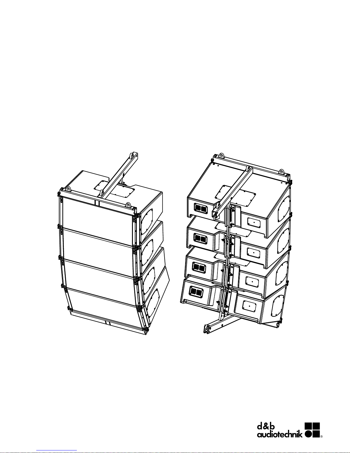
Vi
Rigging manual (1.2 EN)

General information
Vi
Rigging manual
Version: 1.2 EN, 08/2013, D2708.EN .01
Copyright © 2013 by d&b audiotechnik GmbH; all rights
reserved.
Keep this manual with the product or in a safe place
so that it is available for future reference.
When reselling this product, hand over this manual to the new
customer.
If you supply d&b products, please draw the attention of your
customers to this manual. Enclose the relevant manuals with the
systems. If you require additional manuals for this purpose, you
can order them from d&b.
d&b audiotechnik GmbH
Eugen-Adolff-Strasse 134, D-71522 Backnang, Germany
T +49-7191-9669-0, F +49-7191-95 00 00
docadmin@dbaudio.com, www.dbaudio.com

1. Safety................................................................................... 4
1.1. Intended use................................................................ 4
1.2. General safety............................................................. 4
1.3. Load capacity/System safety..................................... 4
1.3.1. Wind loads............................................................... 5
1.4. d&b ArrayCalc calculator software / TI 385............ 5
1.5. Secondary safety......................................................... 5
1.6. Operational safety...................................................... 6
2. Rigging concept and components............................ 7
2.1. Mounting and flying frames....................................... 7
2.1.1. Z5387.000 Vi Mounting frame top....................... 8
2.1.2. Z5387.001 Vi Mounting frame bottom................. 9
2.1.3. Dimensional drawings........................................... 11
2.2. Ring cotters................................................................ 12
2.3. Locking pins............................................................... 13
2.4. Rear/Splay links of the frames................................. 14
2.5. Cabinet's rigging mechanism................................... 16
2.5.1. Front link mechanism............................................. 16
2.5.2. Splay/Rear link mechanism.................................. 17
2.5.3. Setting splay angles for Vi-TOP cabinets............. 17
3. Arrays and assembly................................................. 18
3.1.
Setup preparation..................................................... 19
3.2. Vi8/Vi12 Array......................................................... 19
3.3. Vi-SUB Column.......................................................... 22
3.4. Mixed array.............................................................. 25
4. Safety and system checks......................................... 32
4.1.
Mechanical setup..................................................... 32
4.2. Wiring........................................................................ 32
5. Hoisting and aiming the array............................... 33
5.1.
Hoisting the array..................................................... 33
5.2. Modifying the vertical aiming of the array.............. 33
5.2.1. Dedicated fixing points......................................... 34
6. Care and maintenance / Disposal......................... 35
6.1.
Visual and functional inspection.............................. 35
6.2. Disposal..................................................................... 35
7. Manufacturer's declaration...................................... 36
Contents
d&b Vi Rigging manual (1.2 EN) 3

1.1. Intended use
The Vi rigging components must only be used in conjunction with
d&b Vi loudspeakers as described in this manual.
1.2. General safety
Installation and setup should only be carried out by qualified and
authorized personnel observing the valid national Rules for the
Prevention of Accidents (RPA).
It is the responsibility of the person installing the assembly to ensure
that the suspension/fixing points are suitable for the intended use.
Always carry out a visual and functional inspection of the items
before use. In case there is any doubt as to the proper functioning
and safety of the items, these must be withdrawn from use
immediately.
Please also refer to Þ Chapter 6. "Care and maintenance /
Disposal" on page 35.
1.3. Load capacity/System safety
Z5387.000 Vi Mounting frame top
The Vi Mounting frame top is designed to suspend smaller arrays
of Vi-TOP or Vi-SUB cabinets with a total system weight of up to
136 kg (300 lb) - SWL, which corresponds to a total weight of up
to 4 x Vi-TOP cabinets.
For any other array configuration which exceeds the maximum
permissible system weight for the Vi Mounting frame top, the
Z5380 V Flying frame must be used.
Note: A detailed description of the Z5380 V Flying frame
including the relevant assembly instructions is given in the VSeries Rigging manual, which is supplied with the V Flying
frame.
Z5387.001 Vi Mounting frame bottom
The Z5387.001 Vi Mounting frame bottom is designed as a
pullback device to fix and/or pull back an array with either the
Z5387.000 Vi Mounting frame top or the Z5380 V Flying frame
attached at the top of the array.
Alternatively, the frame can be used as an adapter frame to be
mounted underneath SUB cabinets in mixed array configurations
with the Z5380 V Flying frame on top of the array. In this case, the
frame can support a total system weight of up to 136 kg (300 lb) SWL, which corresponds to a total weight of up to 4 x Vi-TOP
cabinets.
For any other array configuration which exceeds the maximum
permissible system weight for the Vi Mounting frame bottom, the
Z5380 V Flying frame must be used.
Note: A detailed description of the Z5380 V Flying frame
including the relevant assembly instructions is given in the VSeries Rigging manual, which is supplied with the V Flying
frame.
1. Safety
d&b Vi Rigging manual (1.2 EN)4
1.3.1. Wind loads
WARNING!
Potential risk of personal injury and material
damage!
When setting up fixed outdoor installations, unpredictable wind
loads must be taken into account.
The dedicated fixing points for the array assemblies described in
this manual are detailed in Þ Chapter 5. "Hoisting and aiming the
array" on page 33.
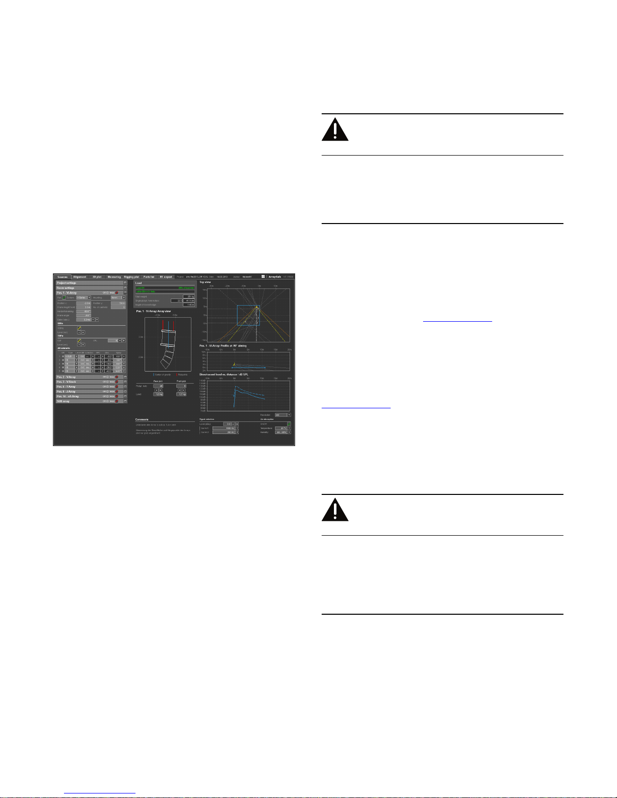
1.4. d&b ArrayCalc calculator software / TI 385
For both acoustic and safety reasons d&b line arrays must be
designed using the d&b ArrayCalc simulation tool. It is available as
a native stand-alone application for both Microsoft Windows (XP
or higher) and Mac OS X (10.4.10 or higher) operating systems
and can be downloaded at www.dbaudio.com.
The use of ArrayCalc is described in "TI 385 d&b Line array
design, ArrayCalc". This TI includes typical array configurations
within the permitted load limits. Carefully read this TI to become
familiar with the operation and behavior of ArrayCalc and in
particular with the mechanical load conditions and limitations.
The TI can be downloaded from the d&b website at
www.dbaudio.com.
1.5. Secondary safety
WARNING!
Potential risk of personal injury and/or
damage to material!
The secondary safety suspension must be independent of the
primary suspension points and capable of carrying the total system
weight.
The additional safety device must be mounted in a way that the
array is caught by the safety device without any drop and swing in
the event that the primary suspension fails.
d&b ArrayCalc
d&b Vi Rigging manual (1.2 EN) 5

1.6. Operational safety
The assembly should always be carried out by two persons.
During assembly pay attention to the possible risk of crushing.
Wear suitable protective clothing.
Observe all instructions given on the respective instruction labels of
the rigging components and loudspeaker cabinets.
When chain hoists are in operation ensure that there is nobody
directly underneath or in the vicinity of the load.
Do not under any circumstances climb on the array.
d&b Vi Rigging manual (1.2 EN)6

2.1. Mounting and flying frames
The d&b Vi loudspeakers are supplemented by two mounting
frames, the Z5387.xxx Vi Mounting frames, one for the top and
one for the bottom of an array.
These frames allows the setup of the following array
configurations:
2. Rigging concept and components
d&b Vi Rigging manual (1.2 EN) 7
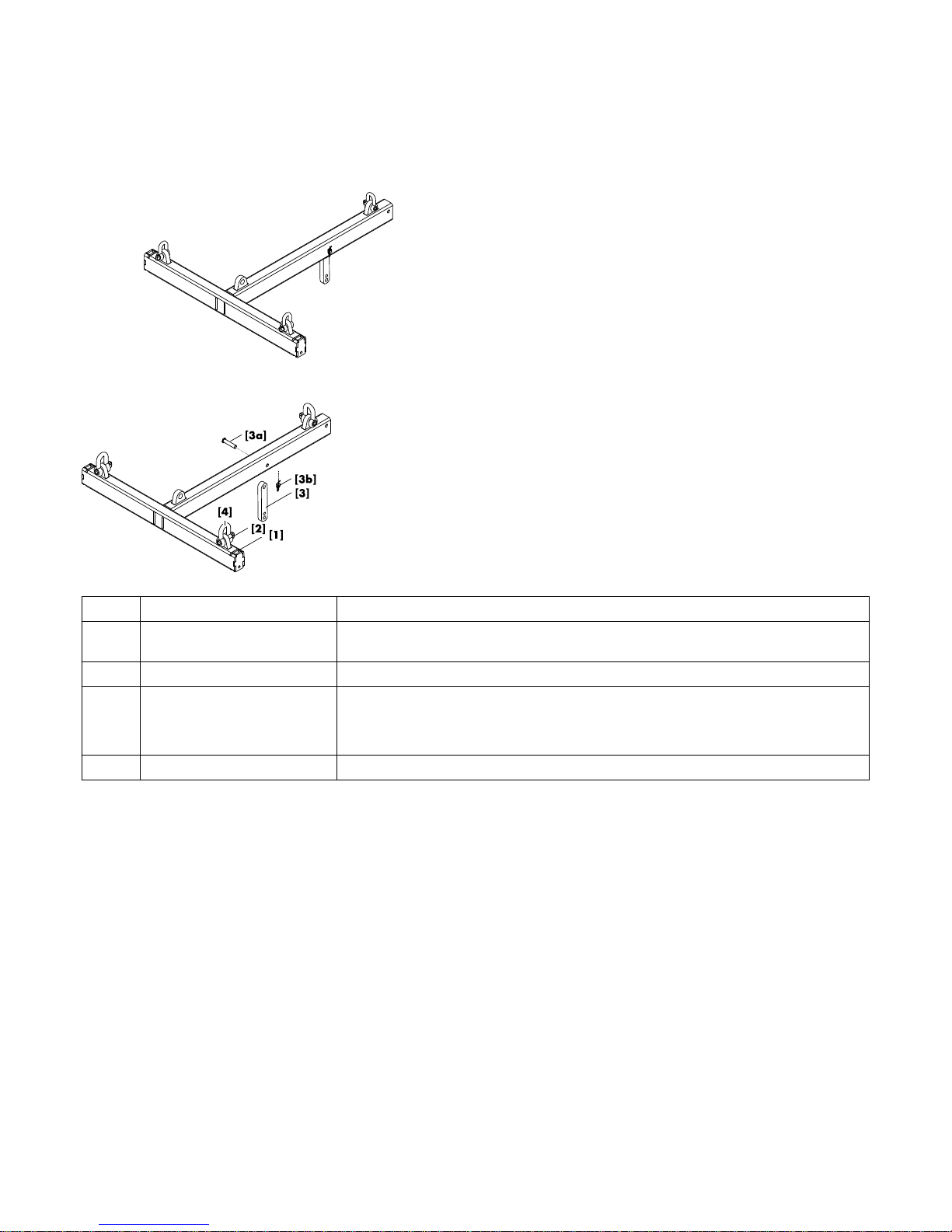
2.1.1. Z5387.000 Vi Mounting frame top
Intended use
The Z5387.000 Vi Mounting frame top is designed to support
arrays with a maximum weight of up to 136 kg (300 lb), which
corresponds to flown configurations of 4 x Vi-TOP or 2 x Vi-SUB
cabinets.
Scope of supply
Please verify the shipment for completeness and proper condition
of the items.
The Z5387.000 Vi Mounting frame top is equipped and supplied
with the following rigging components.
Note: In delivered condition, the Rear/Splay links [3A/B]
are not attached to the frame. For assembly instructions please
refer to Þ Chapter 2.4. "Rear/Splay links of the frames"
Þ Attaching the Splay/Rear links and the O-ring on page
15.
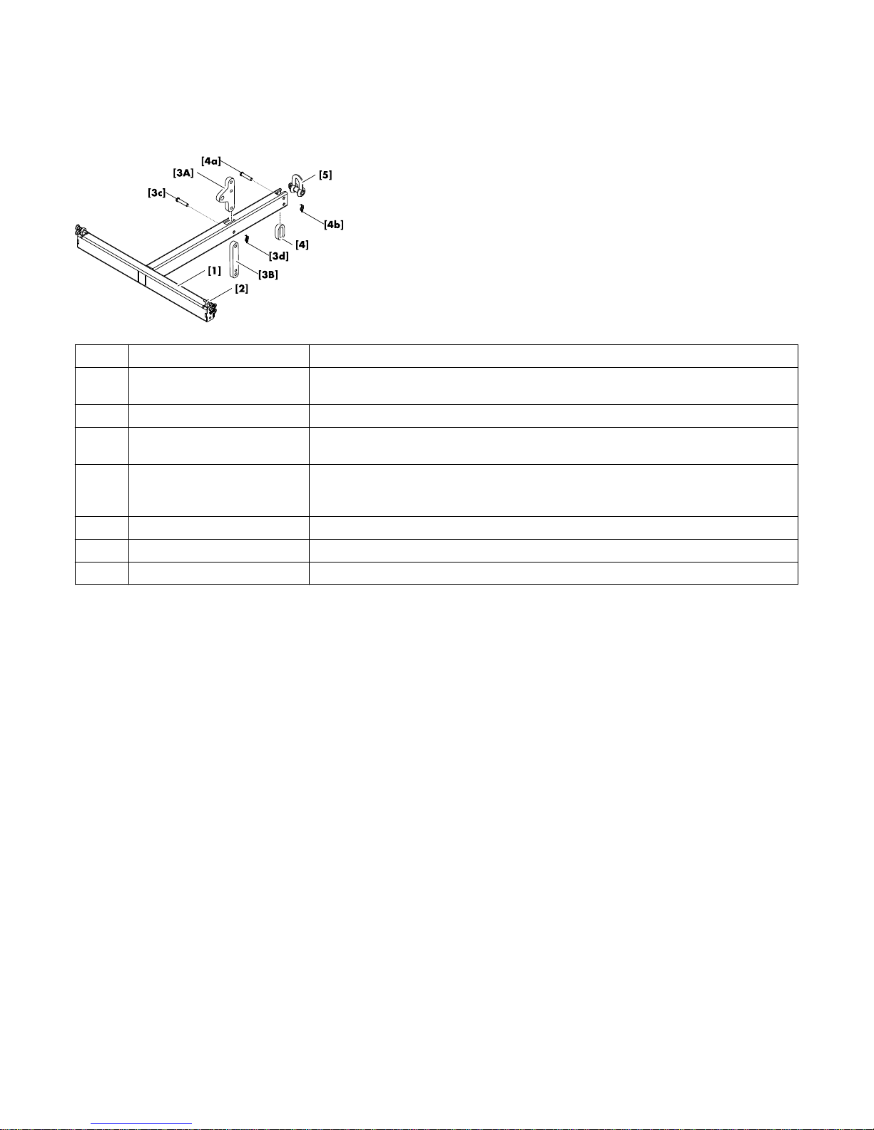
Pos.
Component Description
[1] Z5387.000
Vi Mounting frame top
Weight (including all rigging components): 11.1 kg (24.5 lb).
[2] Fixing points The Mounting frame is equipped with four fixing points for suspension using shackles.
[3] Rear link Rear link including Fixing bolt [3a] and Ring cotter [3b].
In connection with the Front links of the Vi loudspeaker cabinets, the Rear link of the frame is
used to attach the frame to the first cabinet of an array.
[4] 2t Shackle Three 2t shackle are provided for hoisting purposes.
d&b Vi Rigging manual (1.2 EN)8
2.1.2. Z5387.001 Vi Mounting frame bottom
Intended use
The Z5387.001 Vi Mounting frame bottom is designed as a
pullback device to fix and/or pull back an array with either the
Z5387.000 Vi Mounting frame top or the Z5380 V Flying frame
mounted on top of the array.
Alternatively, the frame can be used as an adapter frame to be
attached underneath SUB cabinets in mixed array configurations
with the Z5380 V Flying frame mounted on top of the array. This
allows a maximum of up to 4 x Vi-TOP cabinets to be attached
underneath SUB cabinets.
Note: A detailed description of the Z5380 V Flying frame
including the relevant assembly instructions is given in the VSeries Rigging manual, which is supplied with the V Flying
frame.
NOTICE!
Construction notes
Each side of the tie bar at the front end of the frame is equipped
with a Front link. Both Front links are undetachably attached to the
tie bar using a fixing bolt. Directly above each of these fixing bolts
there is a Locking pin that serves to additionally stabilize the Front
link in its recess. For safety reasons, this Locking pin must always
be inserted and locked.
In addition, there is a second Locking pin on each side of the tie
bar which is used to connect the frame with a cabinet.
d&b Vi Rigging manual (1.2 EN) 9
Scope of supply
Please verify the shipment for completeness and proper condition
of the items.
The Z5387.001 Vi Mounting frame bottom is equipped and
supplied with the following rigging components.
Note: In delivered condition, the Rear link [3] and the O-ring
[4] are not attached to the frame. For assembly instructions
please refer to Þ Chapter 2.4. "Rear/Splay links of the
frames" Þ Attaching the Splay/Rear links and the O-ring on
page 15.
Pos. Component Description
[1] Z5387.001
Vi Mounting frame bottom
Weight (including all rigging components): 9.5 kg (21 lb).
[2] Front links The Mounting frame is equipped with two Front links including the corresponding Locking pins.
[3A] Rear link In connection with the Front links, this rear link is used to attach the frame underneath the last
cabinet of an array.
[3B] Splay link (0°) In connection with the Front links, this additional splay link is used to attach the first TOP
cabinet at 0° underneath SUB cabinets in a mixed array configuration with SUB cabinets at
the top of the array.
[3c/d] Fixing bolt [3c] and Ring cotter [3d].
[4] O-ring Including Fixing bolt [4a] and Ring cotter [4b].
[5] 2t Shackle Additional 2t shackle.
d&b Vi Rigging manual (1.2 EN)10
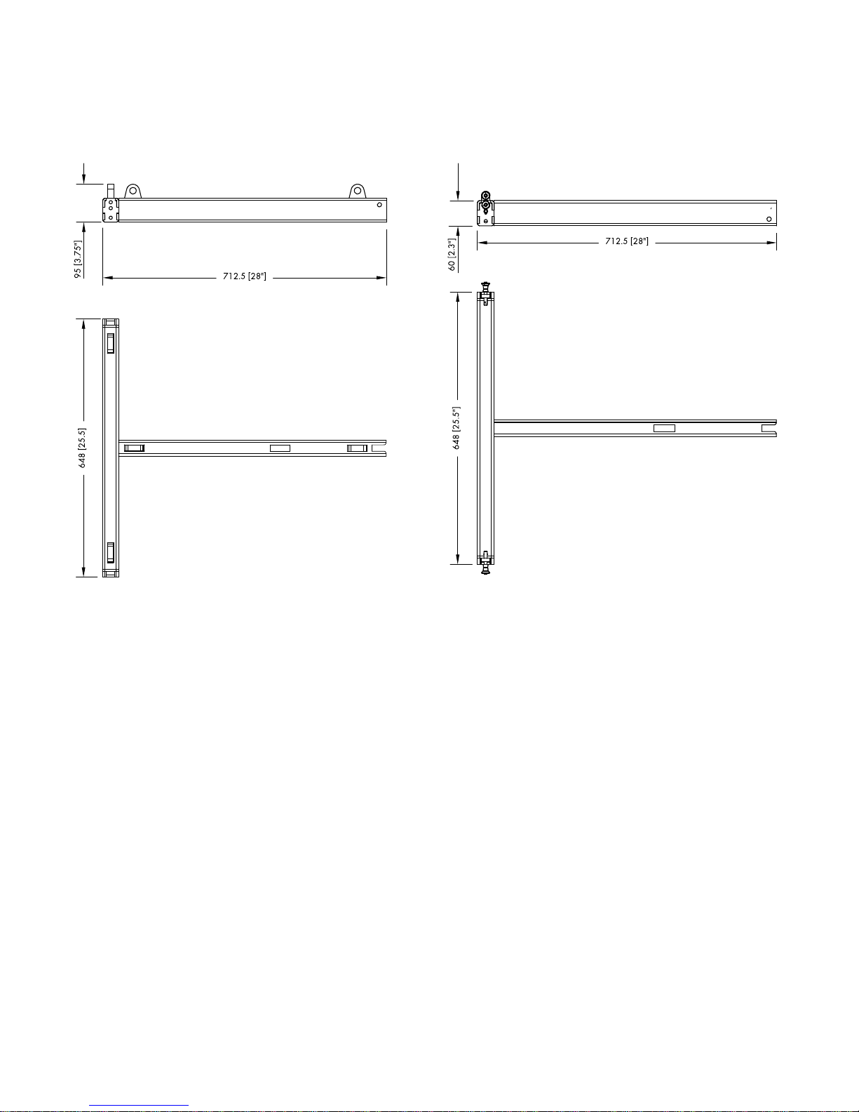
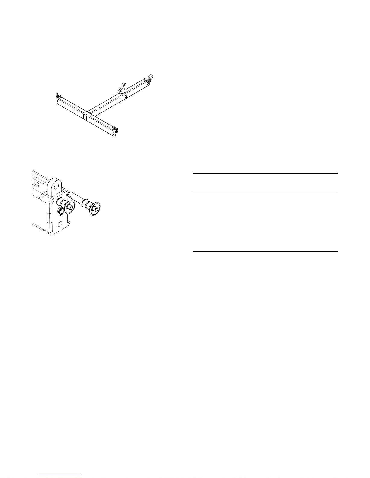
2.1.3. Dimensional drawings
Fig. 2: Z5387.001 Vi Mounting frame bottom,
dimensions in mm [inch]
Fig. 1: Z5387.000 Vi Mounting frame top,
dimensions in mm [inch]
d&b Vi Rigging manual (1.2 EN) 11
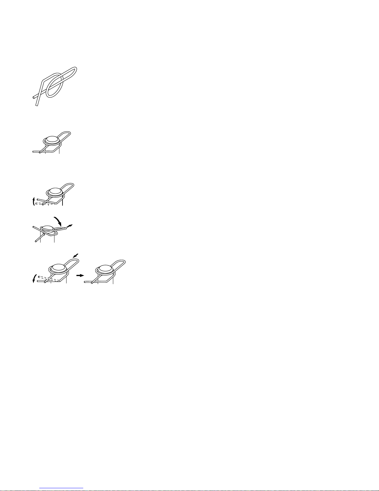
2.2. Ring cotters
In connection with the Vi rigging system, ring cotters are used for
the following items to prevent the respective item from slackening
and/or loosening:
– Fixing bolt of the TOP and SUB cabinet's Rear links.
– Fixing bolt of the frame's Rear links and cable picks.
Function of the ring cotter
By default, the ring cotters are "locked" to prevent them from
loosening.
For modification reasons such as altering the position of the frame's
Splay link or exchanging a shackle, it may be necessary to
temporarily remove the cotter and reattach it afterwards.
For this purpose proceed as follows:
1. Unlock
Unlock the ring cotter by pushing up the front wire loop over
the straight wire shaft.
2. Release and remove
Push down the rear wire loop until the ring cotter snaps over
the edge of the bolt and remove the ring cotter.
3. Refit and lock
Refit the ring cotter by pushing the straight wire shaft through
the hole and pressing the front wire loop underneath the
straight wire shaft.
Fig. 3: Ring cotter
Ring cotter locked
d&b Vi Rigging manual (1.2 EN)12
 Loading...