


MAX

MAX
Manual (5.1 EN)

Symbols on the equipment
Please refer to the information in the operating manual.
WARNING!
Dangerous voltage!
Contents
Safety precautions...............................................................3
Information regarding use of loudspeakers...............................................3
MAX ......................................................................................4
Connections.........................................................................................................4
Operating modes..............................................................................................5
4-wire operation (standard wiring EP5 and NL4).............................5
2-wire operation (NL4 only)....................................................................5
Operation with D6 or D12.............................................................................6
Operation with D6.....................................................................................6
Operation with D12...................................................................................6
Operation with E-PAC......................................................................................8
Operation with P1200A and ampMAX module.......................................9
Operation with P1200A and AMP-L module (NL4 only).......................9
Dispersion characteristics..............................................................................10
Frequency response.......................................................................................10
Technical specifications..................................................................................11
Manufacturer's declarations.............................................12
EU conformity of loudspeakers (CE symbol)...........................................12
WEEE Declaration (Disposal).......................................................................12
General Information
MAX Manual
Version 5.1 EN, 03/2008, D2081.EN.05
Copyright © 2008 by d&b audiotechnik GmbH; all rights reserved.
Keep this manual with the product or in a safe place so that it is
available for future reference.
When reselling this product, hand over this manual to the new
customer.
If you supply d&b products, please draw the attention of your customers
to this manual. Enclose the relevant manuals with the systems. If you
require additional manuals for this purpose, you can order them from
d&b.
d&b audiotechnik GmbH
Eugen-Adolff-Strasse 134, D-71522 Backnang, Germany
Telephone +49-7191-9669-0, Fax +49-7191-95 00 00
E-mail: docadmin@dbaudio.com, Internet: www.dbaudio.com

Safety precautions
Information regarding use of loudspeakers
WARNING!
Never stand in the immediate vicinity of loudspeakers driven at a high
level. Professional loudspeaker systems are capable of causing a
sound pressure level detrimental to human health. Seemingly noncritical sound levels (from approx. 95 dB-SPL) can cause hearing
damage if people are exposed to it over a long period.
In order to prevent accidents when deploying loudspeakers on the
ground or when flown, please take note of the following:
When setting up the loudspeakers or loudspeaker stands, make sure
they are standing on a firm surface. If you place several systems on
top of one another, use straps to secure them against movement.
Only use accessories which have been tested and approved by d&b
for assembly and mobile deployment. Pay attention to the correct
application and maximum load capacity of the accessories as detailed
in our specific "Mounting instructions" or in our "Flying system and
rigging manuals".
Ensure that all additional hardware, fixings and fasteners used for
installation or mobile deployment are of an appropriate size and load
safety factor. Pay attention to the manufacturers' instructions and to
the relevant safety guidelines.
Regularly check the loudspeaker housings and accessories for visible
signs of wear and tear and replace them when necessary.
Regularly check all load bearing bolts in the mounting devices.
CAUTION!
Loudspeakers produce a static magnetic field even if they are not
connected or are not in use. Therefore make sure when erecting and
transporting loudspeakers that they are nowhere near equipment and
objects which may be impaired or damaged by an external magnetic
field. Generally speaking, a distance of 0.5 m (1.5 ft) from magnetic
data carriers (floppy disks, audio and video tapes, bank cards, etc.) is
sufficient; a distance of more than 1 m (3 ft) may be necessary with
computer and video monitors.
MAX Manual (5.1 EN) Safety precautions - 1
MAX
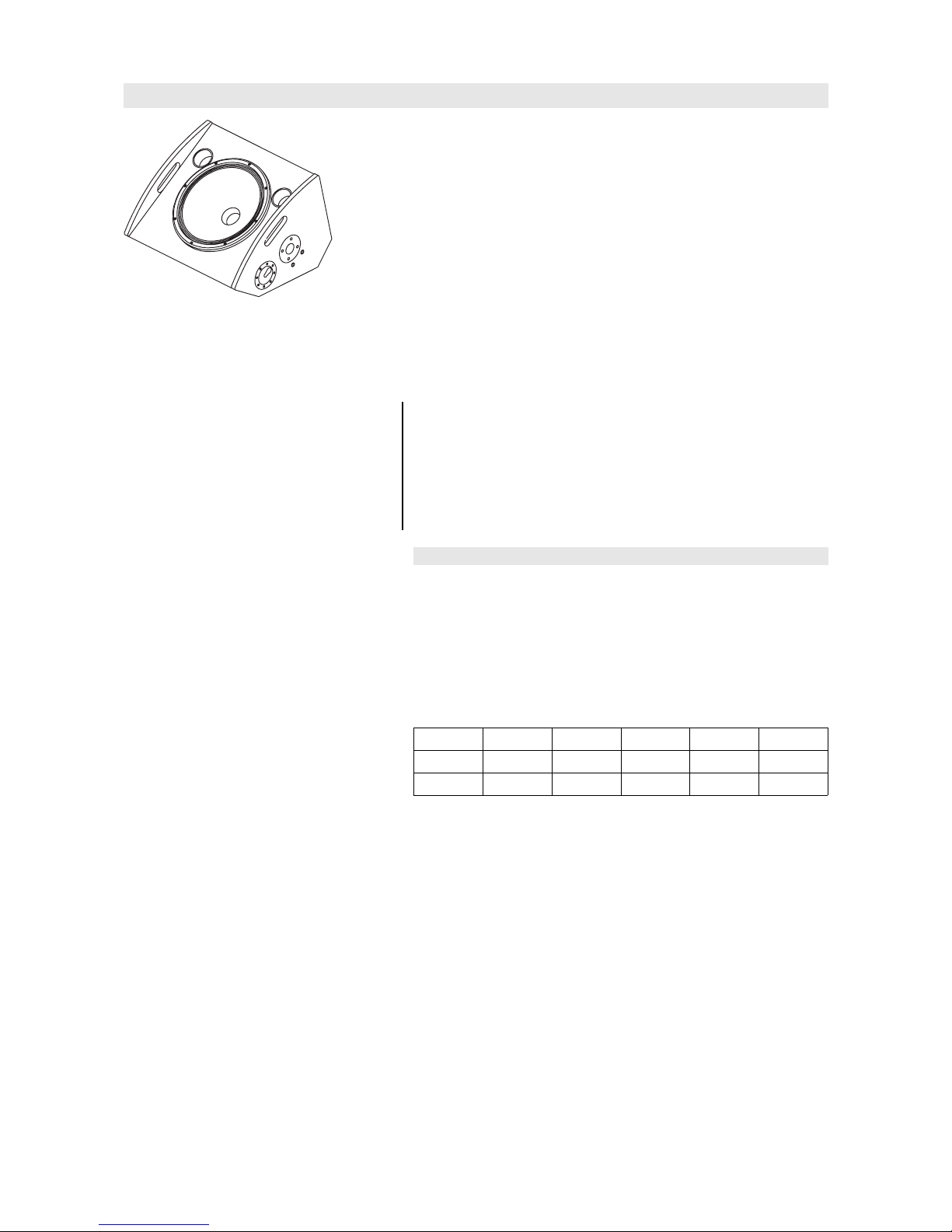
MAX loudspeaker
MAX is a 2-way floor monitor employing a 15“/2“ coaxial driver
combination with a passive crossover. The driver design allows the use
of a compact, low height cabinet. MAX can be driven actively or
passively.
Coaxially mounting the 2“ HF and 15“ LF drivers creates a very
compact single driver whilst retaining the benefits of separate magnetic
assemblies. The drivers are positioned together to utilize the combined
shape and geometry of the LF cone and HF horn to create a single
waveguide with a controlled, symmetrical 60° conical dispersion.
The MAX cabinet is constructed from marine plywood and has an
impact resistant paint finish. The front of the loudspeaker cabinet is fitted
with a rigid metal grill covered with a replaceable acoustically
transparent foam. A socket to accept a loudspeaker stand, a ratchet
strap kelping bar and optional MAN CF4 stud plate rigging points
complete the possible rigging options for MAX.
NOTICE:
Only operate MAX cabinets with a correctly configured d&b amplifier,
otherwise there is a risk of damaging the loudspeaker components.
As an alternative other high quality power amplifiers may be used,
provided their output power does not exceed 500 Watts into 8 ohms
and an additional subsonic filter is used (25 Hz with 12 dB/octave
minimum), otherwise there is a risk of damaging the loudspeaker
components.
Connections
The MAX cabinet is fitted with two EP5 connectors. All pins of both
connectors are wired in parallel.
Using one connector as the input, the second connector allows for direct
connection to additional cabinets.
The MAX cabinet can be supplied with NL4 output connectors as an
option.
Pin equivalents of EP5 and NL4 connectors are listed in the table below.
LF+ LF- HF+ HF- n.a.
EP5
1 2 3 4 5
NL4
1+ 1- 2+ 2- n.a.
MAX Manual (5.1 EN) Page 4 of 12
 Loading...