


 Loading...
D |
D80 |
|
Manual 1.9 en |
|
|

General information
D80 Manual
Version: 1.9 en, 06/2015, D2020.EN .01
Copyright © 2015 by d&b audiotechnik GmbH; all rights reserved.
Keep this manual with the product or in a safe place so that it is available for future reference.
We recommend you to regularly check the d&b website for the latest version of this manual.
When reselling this product, hand over this manual to the new customer.
If you supply d&b products, please draw the attention of your customers to this manual. Enclose the relevant manuals with the systems. If you require additional manuals for this purpose, you can order them from d&b.
d&b audiotechnik GmbH
Eugen-Adolff-Strasse 134, D-71522 Backnang, Germany T +49-7191-9669-0, F +49-7191-95 00 00 docadmin@dbaudio.com, www.dbaudio.com

IMPORTANT SAFETY INSTRUCTIONS
Explanation of graphical symbols
The lightning symbol within a triangle is intended to alert the user to the presence of uninsulated "dangerous voltages" within the unit’s chassis that may be of sufficient magnitude to constitute a risk of electric shock to humans.
Before using this product, carefully read the applicable items of the following safety instructions.
1.Keep these instructions for future reference.
2.Read these instructions.
3.Heed all warnings.
4.Follow all instructions.
5.Keep water or other liquids away from the unit. Do not place liquid filled containers, for example beverages, on top of the unit.
6.Do not operate the unit while it is wet or standing in liquid.
7.Always operate the unit with the chassis ground wire connected to the electrical safety earth. Do not defeat the safety purpose of a grounding-type plug. A grounding-type plug has two blades and a third grounding prong. The third prong is provided for your safety. If the provided plug does not fit into your outlet, consult an electrician for replacement of the obsolete outlet.
8.Do not use this unit if the power cord is damaged or frayed. Protect the power cord from being walked upon or pinched, particularly at the plugs and the point where it exits from the apparatus.
9.The unit is intended for use in a 19" rack. Follow the mounting instructions. When a rack on wheels is used, exercise caution when moving the loaded rack to avoid injury from tipping over.
10.Unplug this apparatus during lightning storms or when unused for long periods of time.
The exclamation point within a triangle is intended to alert the user to the presence of important operating and service instructions in the literature accompanying the product.
11.Never connect an output pin to any other amplifier input or output pin or to the earth (ground). This may damage the unit or lead to electric shock.
12.Lay all cables connected to the unit carefully so that they cannot be crushed by vehicles or other equipment and that no one can either step on them or trip over them.
13.Refer all servicing to qualified service personnel. Servicing is required when the apparatus has been damaged in any way such as:
–Power-supply cord or plug is damaged.
–Liquid has been spilled into the unit.
–An object has fallen into the unit.
–The unit has been exposed to rain or moisture.
–The unit does not operate normally.
–The unit was dropped or the chassis is damaged.
–Do not remove top or bottom covers. Removal of the covers will expose hazardous voltages. There are no user serviceable parts inside and removal may void the warranty.
14.Use the mains plug as the disconnecting device and keep it readily accessible. If the mains plug is not readily accessible due to mounting in a 19" rack, then the mains plug for the entire rack must be readily accessible.
15.An experienced user must always supervise the equipment, especially if inexperienced adults or minors are using the equipment.
d&b D80 Manual 1.9 en |
3 |

Contents
1. |
Introduction........................................................................ |
6 |
|
1.1. |
Intended use............................................................................ |
6 |
|
1.2. |
D80 Concept........................................................................... |
6 |
|
2. |
Technical specifications.................................................. |
8 |
|
3. |
Scope of supply.............................................................. |
10 |
|
4. |
Startup............................................................................... |
11 |
|
4.1. |
Overview............................................................................... |
11 |
|
4.2. Rack mounting and cooling................................................. |
12 |
||
4.3. |
Connections.......................................................................... |
14 |
|
4.3.1. |
Mains connection.............................................................. |
14 |
|
4.3.2. Audio INPUT and LINK connectors................................. |
16 |
||
4.3.3. |
Output connectors............................................................. |
17 |
|
4.3.4. ETHERNET (Dual Ethernet port)........................................ |
18 |
||
4.3.5. |
CAN (CAN-Bus)................................................................ |
19 |
|
4.4. |
Controls and indicators........................................................ |
20 |
|
4.4.1. |
Mains power switch.......................................................... |
20 |
|
4.4.2. |
Display - User interface..................................................... |
20 |
|
4.4.3. |
Standby mode................................................................... |
21 |
|
4.4.4. |
Mute functions................................................................... |
22 |
|
5. |
User interface.................................................................. |
23 |
|
5.1. |
Operating concept............................................................... |
23 |
|
5.2. Screen layout and conventions............................................ |
24 |
||
5.3. Screen items and views........................................................ |
24 |
||
5.3.1. |
Function buttons................................................................. |
24 |
|
5.3.2. |
Navigation buttons............................................................ |
24 |
|
5.3.3. |
Input fields.......................................................................... |
25 |
|
5.3.4. |
Input masks........................................................................ |
25 |
|
5.3.5. |
Information fields............................................................... |
25 |
|
6. |
Home screen.................................................................... |
26 |
|
6.1. |
Header area - Device........................................................... |
27 |
|
6.2. |
Data area - Channel strip(s)................................................. |
27 |
|
7. |
Channel strip.................................................................... |
28 |
|
8. |
Basic settings - Quick reference............................... |
30 |
|
9. |
Device setup..................................................................... |
32 |
|
9.1. |
Device name......................................................................... |
33 |
|
9.2. |
Input....................................................................................... |
34 |
|
9.2.1. |
Input mode......................................................................... |
34 |
|
9.3. |
Output................................................................................... |
36 |
|
9.3.1. |
Output mode..................................................................... |
37 |
|
9.4. |
Remote................................................................................... |
41 |
|
9.4.1. |
IP settings........................................................................... |
41 |
|
9.4.2. |
Remote ID.......................................................................... |
42 |
|
9.5. |
More...................................................................................... |
42 |
|
9.5.1. |
Preferences........................................................................ |
42 |
|
9.5.1.1. |
Display............................................................................ |
43 |
|
9.5.1.2. |
Lock................................................................................. |
43 |
|
9.5.1.3. |
Preferences/More.......................................................... |
45 |
|
9.5.1.3.1. |
System reset................................................................ |
46 |
|
9.5.2. |
Info..................................................................................... |
46 |
|
9.5.3. |
Levels.................................................................................. |
47 |
|
9.5.4. Mains current limiter (MCL).............................................. |
48 |
||
9.5.5. |
AmpPresets........................................................................ |
49 |
|
4 |
d&b D80 Manual 1.9 en |
|
|
|
|
9.5.6. |
|
.................................................................................Scope |
50 |
10. |
Channel setup.................................................................. |
51 |
|
10.1. |
|
Channel name.................................................................... |
52 |
10.2. Configuration switches - Filter_1, _2, _3.......................... |
53 |
||
10.3. |
|
Level.................................................................................... |
53 |
10.4. |
|
EQ - Equalizer ................................................................... |
53 |
10.5. |
|
DLY - Delay......................................................................... |
56 |
10.6. |
|
Input routing........................................................................ |
56 |
10.7. |
|
System check/LM............................................................... |
57 |
10.7.1. |
System check................................................................... |
57 |
|
10.7.2. |
Load monitoring (LM)..................................................... |
58 |
|
10.8. |
|
Speaker............................................................................... |
59 |
10.8.1. |
ArrayProcessing (AP)...................................................... |
61 |
|
10.8.2. |
LoadMatch...................................................................... |
62 |
|
10.8.3. |
LINEAR setup................................................................... |
63 |
|
10.9. |
|
Frequency generator - Freq. gen....................................... |
63 |
11. |
Web Remote interface................................................. |
65 |
|
12. |
Operation (Hardware references)......................... |
68 |
|
12.1. |
|
Power supply...................................................................... |
68 |
12.1.1. Active Power Factor Correction (PFC)........................... |
68 |
||
12.1.2. Automatic mains range selection................................... |
68 |
||
12.1.3. |
Mains voltage monitoring.............................................. |
68 |
|
12.1.4. Mains inrush current limiter............................................ |
69 |
||
12.1.5. |
Mains supply requirements............................................ |
69 |
|
12.1.6. |
Generator operation/UPS requirements....................... |
70 |
|
12.2. |
|
Power amplifiers................................................................. |
70 |
12.3. |
|
Cooling fans....................................................................... |
71 |
12.4. Current/power draw and thermal dissipation.................. |
71 |
||
13. |
Service/Maintenance and care................................ |
73 |
|
13.1. |
|
Service................................................................................. |
73 |
13.2. |
|
Maintenance and care...................................................... |
73 |
13.2.1. |
Touch screen cleaning.................................................... |
73 |
|
13.2.2. |
Touch screen calibration................................................. |
74 |
|
14. |
Manufacturer's Declarations.................................... |
75 |
|
14.1. EU declaration of conformity (CE symbol)....................... |
75 |
||
14.2. |
|
WEEE Declaration (Disposal)............................................ |
75 |
14.3. |
|
Licenses and Copyright...................................................... |
75 |
15. |
Appendix.......................................................................... |
76 |
|
15.1. |
|
System check - References................................................. |
76 |
15.2. Max. number of cabinets operated in parallel................ |
78 |
||
15.3. |
|
Error messages................................................................... |
80 |
d&b D80 Manual 1.9 en |
5 |

1. Introduction
D80 Front view
D80 User interface
1.1. Intended use
The d&b D80 amplifier is designed for mobile applications and intended to be used with all current d&b loudspeakers. A LINEAR setup is available allowing the D80 to be used as a linear power amplifier.
NOTICE!
The device complies with the electromagnetic compatibility requirements of EN 55103 (product family standard for audio, video, audio-visual and entertainment lighting control apparatus for professional use) for the environments E1 (residential), E2 (business and commercial), E3 (outdoor use in urban areas) and E4 (outdoor use in rural areas).
Acoustic interference and malfunctions may occur if the unit is operated in the immediate vicinity of high-frequency transmitters (e.g. wireless microphones, mobile phones, etc.). Damage to the device is unlikely, but cannot be excluded.
1.2. D80 Concept
The D80 amplifier represents the next generation of high power four channel Class D amplifiers. It is developed and manufactured by d&b using Digital Signal Processing (DSP) to incorporate loudspeaker specific configurations and user definable setups, equalization and delay functions. The amplifier is designed to fully drive all d&b loudspeakers and provide comprehensive management and protection capabilities. This high performance amplifier provides the power density required for both touring and installation purposes while the powerful signal processing extends the level of functionality of the on-board features.
The user interface of the amplifier consists of two elements: a color TFT touch screen providing visual information and quick access to the amplifier settings and a rotary encoder on the front panel for data input purposes. To allow ease of operation when the amplifier is below eye level, the front panel and the integrated display are tilted upwards. As a result, the front panels of multiple amplifiers on top of each other within a rack integrate to form one large control surface.
The user definable equalizer features two independent 16-band EQ groups within each channel. These provide parametric, notch, shelving and asymmetric filters as well as a graphic EQ (via the d&b R1 Remote control software V2) allowing instant switching between two EQ curves for comparison. The delay capability covers a range of up to 10 s. All loudspeaker specific functions such as CUT, HFA, HFC, CSA or CPL are available. The DSP unit of the amplifier has a fixed latency of 0.3 ms.
6 |
d&b D80 Manual 1.9 en |

D80 Rear view
The amplifier enables up to four input channels, which may be four analog inputs, two analog and two AES channels or four AES channels. Each input channel can be routed to any of the output channels A to D. XLR connectors 2 and 4 of the D80 can be used as either digital or analog inputs, connectors 1 and 3 are analog inputs. Link outputs are supplied for all inputs. This 1:1 ratio of inputs to amplifier output channels increases flexibility of application, particularly for use as monitor, frontfill or effect channels.
The D80 amplifier outputs are optionally NL4 or EP5 connectors plus one centered NL8 connector with all pins driven. The latter serves as an interface to a rack panel or to loudspeaker multicores and breakout adapters. To simplify configuration, the output mode of the amplifier can be configured like a set of two dual channel amplifiers providing Dual Channel, Mix TOP/SUB or 2-Way Active modes for the left and the right channels A/B and C/D, respectively.
For applicable loudspeakers, d&b LoadMatch enables the D80 amplifier to electrically compensate for the properties of the cable used to connect the loudspeakers to the amplifier output. This function which covers a bandwidth of up to 20 kHz preserves the tonal balance when cable lengths of up to 70 m (230 ft) are used. Due to its design LoadMatch does not require additional wires and is therefore applicable with any connector type used.
To provide optimum compensation, cable length and crosssectional data as well as the number of loudspeakers connected to the amplifier channel can be entered on the amplifier.
The D80 utilizes a switch mode power supply with active Power Factor Correction (PFC) to produce a clean current draw and ensure stable and efficient performance under adverse mains conditions. The high power capabilities provide increased power to fully drive all applicable d&b loudspeaker cabinets and sufficient headroom for any future systems.
Remote control and full system integration are realized using the d&b ArrayCalc simulation software and R1 Remote control software V2. The D80 amplifier includes two Ethernet ports on etherCON connectors to enable daisy chaining. Both Ethernet and dbCAN protocols are incorporated. The Ethernet protocol implemented in the d&b R1 Remote control software V2 and the D80 amplifier is a protocol developed by the OCA Alliance (Open Control Architecture Alliance), of which d&b is a founding member. For further details, please refer to the OCA website: www.oca-alliance.com.
d&b D80 Manual 1.9 en |
7 |

2. Technical specifications
Audio data (linear setting with subsonic filter)
Maximum output power per channel (THD + N < 0.5%, all channels driven)
CF = 6 dB @ 4/8 ohms |
4 x 2600/2000 W |
CF = 12 dB @ 4/8 ohms |
4 x 4000/2000 W |
Maximum output voltage |
180 V |
Frequency response (—1 dB) |
35 Hz – 20 kHz |
THD+N 20 Hz – 20 kHz, 600 W @ 4 ohms) |
< 0.5% |
S/N ratio (unweighted, RMS) |
|
Analog input |
> 110 dBr |
Digital input |
> 114 dBr |
Damping factor (20 Hz – 200 Hz into 4 ohms) |
> 100 |
Crosstalk (20 Hz – 20 kHz) |
< –70 dBr |
Gain (Linear mode @ 0 dB) |
31 dB |
Protection circuits
Mains inrush current limiter |
13 A RMS @ 230 V AC |
|
22 A RMS @ 120 V AC |
Ground fault protection |
27 A RMS @ 100 V AC |
|
|
Output current limitation/protection |
65 A / 75 A |
Output DC offset protection |
10 V |
Output HF Voltage Limiter |
60 V @ 10 kHz |
Output pop-noise suppression |
|
Mains Current Limitation (MCL) |
95 to 50 % of 16 / 30 A |
Overvoltage protection |
Up to 400 V AC |
Self-resetting overtemperature protection |
|
Power supply
Autosensing switched mode power supply with active power factor correction (PFC)
Mains connector
Rated mains voltage
Mains fuse
Power consumption (typical values)
Standby |
9 W |
|
Idle |
180 |
W |
Max. power consumption (short term RMS) |
7000 |
W |
Audio input connectors
INPUT analog (A1 - A4) |
|
3 pin XLR female |
Pin assignment |
1 = GND, 2 = pos., 3 = neg. |
|
Input impedance |
38 kOhms, electronically balanced |
|
Common mode rejection (CMRR @ 100 Hz/10 kHz) |
> 70 / 50 dB |
|
Maximum input level (balanced/unbalanced) |
+25 / 17 dBu |
|
|
|
+27 dBu @ 0 dBFS |
LINK analog (A1 - A4) |
|
3 pin XLR male |
Pin assignment |
1 = GND, 2 = pos., 3 = neg. |
|
|
|
parallel to input |
INPUT digital (D1/2, D3/4) |
3 pin XLR female, AES 3 |
|
Pin assignment |
1 = GND, 2 = AES Signal, 3 = AES Signal |
|
Input impedance |
110 ohms, transformer balanced |
|
Sampling |
48 / 96 kHz / 2 Ch/n |
|
Synchronization |
Word-Sync: PLL-locked to source (slave mode) |
|
LINK digital (Output) |
|
3 pin XLR male |
|
electronically balanced |
|
analog signal buffering (refresh), power fail relay (Bypass) |
||
Output connectors
SPEAKER OUTPUTS A/B/C/D |
4 x NL4 |
|
optional: 4 x EP5 |
4 CHANNEL OUTPUT |
1 x NL8 |
Network connectors
CAN |
2 x RJ 45 parallel |
ETHERNET |
2 x etherCON® |
|
Dual Ethernet port with built-in 2-port Ethernet switch |
|
10/100 Mbit |
Controls and indicators
POWER |
Mains power switch |
SCROLL/EDIT |
Digital rotary encoder |
Display |
TFT color touch screen, 3.5" / 320 x 240 Pixel |
8 |
d&b D80 Manual 1.9 en |

Digital Signal Processing
System start-up time |
|
|
|
|
|
|
|
|
|
|
|
|
17 sec. |
||||||||||||||||||||||||||||||||||||||
Sampling rate |
|
96 kHz / 27 Bit ADC / 24 Bit DAC |
|||||||||||||||||||||||||||||||||||||||||||||||||
Latency analog input |
|
|
|
|
|
|
|
|
0.3 msec. |
||||||||||||||||||||||||||||||||||||||||||
Latency digital input (AES) |
|
|
|
|
|
|
|
|
0.3 msec. |
||||||||||||||||||||||||||||||||||||||||||
|
|
|
|
|
|
|
|
|
|
|
|
|
|
|
|
|
|
|
|
|
|
|
|
|
|
|
|
|
|
|
|
|
|
|
|
|
|
|
|
48 kHz / 96 kHz |
|||||||||||
Input dynamic |
|
|
|
|
|
|
|
|
> 127 dB |
||||||||||||||||||||||||||||||||||||||||||
ADC dynamic |
|
|
|
|
|
|
|
|
> 110 dB |
||||||||||||||||||||||||||||||||||||||||||
DAC dynamic |
|
|
|
|
|
|
|
|
> 110 dB |
||||||||||||||||||||||||||||||||||||||||||
Equalizer |
two user definable 16-band equalizers |
||||||||||||||||||||||||||||||||||||||||||||||||||
|
|
|
|
|
|
|
|
|
|
|
|
|
|
|
|
|
|
|
|
|
|
|
|
|
|
|
|
|
|
|
|
|
|
|
|
Filter types: PEQ/Notch/HiShlv/LoShlv/Asym |
|||||||||||||||
Delay |
|
|
|
|
0.3 msec. - 10 sec. |
||||||||||||||||||||||||||||||||||||||||||||||
Frequency generator |
Pink noise or Sine wave 10 Hz – 20 kHz |
||||||||||||||||||||||||||||||||||||||||||||||||||
|
|
|
|
|
|
|
|
|
|
|
|
|
|
|
|
|
|
|
|
|
|
|
|
|
|
|
|
|
|
|
|
|
|
|
|
|
|
|
|
|
|
|
|
|
|
|
|
|
|
|
|
|
|
|
|
|
|
|
|
|
|
|
|
|
|
|
|
|
|
|
|
|
|
|
|
|
|
|
|
|
|
|
|
|
|
|
|
|
|
|
|
|
|
|
|
|
|
|
|
|
|
|
|
|
|
|
|
|
|
|
|
|
|
|
|
|
|
|
|
|
|
|
|
|
|
|
|
|
|
|
|
|
|
|
|
|
|
|
|
|
|
|
|
|
|
|
|
|
|
|
|
|
|
|
|
|
|
|
|
|
|
|
|
|
|
|
|
|
|
|
|
|
|
|
|
|
|
|
|
|
|
|
|
|
|
|
|
|
|
|
|
|
|
|
|
|
|
|
|
|
|
|
|
|
|
|
|
|
|
|
|
|
|
|
|
|
|
|
|
|
|
|
|
|
|
|
|
|
|
|
|
|
|
|
|
|
|
|
|
|
|
|
|
|
|
|
|
|
|
|
|
|
|
|
|
|
|
|
|
|
|
|
|
|
|
|
|
|
|
|
|
|
|
|
|
|
|
|
|
|
|
|
|
|
|
|
|
|
|
|
|
|
|
|
|
|
|
|
|
|
|
|
|
|
|
|
|
|
|
|
|
|
|
|
|
|
|
|
|
|
|
|
|
|
|
|
|
|
|
|
|
|
|
|
|
|
|
|
|
|
|
|
|
|
|
|
|
|
|
|
|
|
|
|
|
|
|
|
|
|
|
|
|
|
|
|
|
|
|
|
|
|
|
|
|
|
|
|
|
|
|
|
|
|
|
|
|
|
|
|
|
|
|
|
|
|
|
|
|
|
|
|
|
|
|
|
|
|
|
|
|
|
|
|
|
|
|
|
|
|
|
|
|
|
|
|
|
|
|
|
|
|
|
|
|
|
|
|
|
|
|
|
|
|
|
|
|
|
|
|
|
|
|
|
|
|
|
|
|
|
|
|
|
|
|
|
|
|
|
|
|
|
|
|
|
|
|
|
|
|
|
|
|
|
|
|
|
|
|
|
|
|
|
|
|
|
|
|
|
|
|
|
|
|
|
|
|
|
|
|
|
|
|
|
|
|
|
|
|
|
|
|
|
|
|
|
|
|
|
|
|
|
|
|
|
|
|
|
|
|
|
|
|
|
|
|
|
|
|
|
|
|
|
|
|
|
|
|
|
|
|
|
|
|
|
|
|
|
|
|
|
|
|
|
|
|
|
|
|
|
|
|
|
|
|
|
|
|
|
|
|
|
|
|
|
|
|
|
|
|
|
|
|
|
|
|
|
|
|
|
|
|
|
|
|
|
|
|
|
|
|
|
|
|
|
|
|
|
|
|
|
|
|
|
|
|
|
|
|
|
|
|
|
|
|
|
|
|
|
|
|
|
|
|
|
|
|
|
|
|
|
|
|
|
|
|
|
|
|
|
|
|
|
|
|
|
|
|
|
|
|
|
|
|
|
|
|
|
|
|
|
|
|
|
|
|
|
|
|
|
|
|
|
|
|
|
|
|
|
|
|
|
|
|
|
|
|
|
|
|
|
|
|
|
|
|
|
|
|
|
|
|
|
|
|
|
|
|
|
|
|
|
|
|
|
|
|
|
|
|
|
|
|
|
|
|
|
|
|
|
|
|
|
|
|
|
|
|
|
|
|
|
|
|
|
|
|
|
|
|
|
|
|
|
|
|
|
|
|
|
|
|
|
|
|
|
|
|
|
|
|
|
|
|
|
|
|
|
|
|
|
|
|
|
|
|
|
|
|
|
|
|
|
|
|
|
|
|
|
|
|
|
|
|
|
|
|
|
|
|
|
|
|
|
|
|
|
|
|
|
|
|
|
|
|
|
|
|
|
|
|
|
|
|
|
|
|
|
|
|
|
|
|
|
|
|
|
|
|
|
|
|
|
|
|
|
|
|
|
|
|
|
|
|
|
|
|
|
|
|
|
|
|
|
|
|
|
|
|
|
|
|
|
|
|
|
|
|
|
|
|
|
|
|
|
|
|
|
|
|
|
|
|
|
|
|
|
|
|
|
|
|
|
|
|
|
|
|
|
|
|
|
|
|
|
|
|
|
|
|
|
|
|
|
|
|
|
|
|
|
|
|
|
|
|
|
|
|
|
|
|
|
|
|
|
|
|
Operating conditions
Temperature range* |
–10 °C ... +40 |
°C / +14 °F ... +104 |
°F |
|
|
*continuous operation |
|
Temperature range** |
–10 °C ... +50 |
°C / +14 °F ... +122 |
°F |
|
**reduced output power or short term operation |
||
Storage temperature |
–20 °C ... +70 °C / –4 °F ... +158 |
°F |
|
Humidity (rel.), long term average |
70% |
||
Fan noise emission
Rack mounted, measured on axis, 1 m to front panel, A-weighting
Idle |
34 dB(A) |
|
Ambient temperature 22 °C / 71.6 °F |
Max. RPM |
49 dB(A) |
Dimensions and weight
|
|
|
Height x width x depth |
|
2 RU x 19" x 530.5 mm |
|||||||||
|
|
|
|
|
|
|
|
|
|
2 RU x 19" x 20.9" |
||||
|
|
|
Weight |
|
19 kg / 42 lb |
|||||||||
|
|
|
|
|
|
|
|
|
|
|
|
|
|
|
|
|
|
|
|
|
|
|
|
|
|
|
|
|
|
|
|
|
|
|
|
|
|
|
|
|
|
|
|
|
|
|
|
|
|
|
|
|
|
|
|
|
|
|
|
|
|
|
|
|
|
|
|
|
|
|
|
|
|
|
|
|
|
|
|
|
|
|
|
|
|
|
|
|
|
|
|
|
|
|
|
|
|
|
|
|
|
|
|
|
|
|
|
|
|
|
|
|
|
|
|
|
|
|
|
D80 enclosure dimensions in mm [inch]
d&b D80 Manual 1.9 en |
9 |

3. Scope of supply
Before starting up the device, please verify the shipment for completeness and proper condition of the items.
If there is any sign of obvious damage to the unit and/or the power cord, do not operate the unit and contact your local dealer from whom you received it.
|
|
|
|
|
|
|
|
|
|
|
|
|
|
|
|
|
|
|
|
|
|
|
|
|
|
|
|
|
|
|
|
|
|
|
|
|
|
|
|
|
|
|
|
|
|
|
|
|
|
|
|
|
|
|
|
|
|
|
|
|
|
|
|
|
|
|
|
|
|
|
|
|
|
|
|
|
|
|
|
|
|
|
|
|
|
|
|
|
|
|
|
|
|
|
|
|
|
|
|
|
|
|
|
|
|
|
|
|
|
|
|
|
|
|
|
|
|
|
|
|
|
|
|
|
|
|
|
|
|
|
|
|
|
|
|
|
|
|
|
|
|
|
|
|
|
|
|
|
|
|
|
|
|
|
|
|
|
|
|
|
|
|
|
|
|
|
|
|
|
|
|
|
|
|
|
|
|
|
|
|
|
|
|
|
|
|
|
|
|
|
|
|
|
|
|
|
|
|
|
|
|
|
|
|
|
|
|
|
|
|
|
|
|
|
|
|
|
|
|
|
|
|
|
|
|
|
|
|
|
|
|
|
|
|
|
|
|
|
|
|
|
|
|
|
|
|
|
|
|
|
|
|
|
|
|
|
|
|
|
|
|
|
|
|
|
|
|
|
|
|
|
|
|
|
|
|
|
|
|
|
|
|
|
|
|
|
|
|
|
|
|
|
|
|
|
|
|
|
|
|
|
|
|
|
|
|
|
|
|
|
|
|
|
|
|
|
|
|
|
|
|
|
|
|
|
|
|
|
|
Pos. |
Qty. |
d&b Code |
Description |
||||||||||||||||||
[1] |
1 |
|
|
|
Z2710 |
d&b D80 Amplifier, dependent on chosen output option (NL4 or EP5 output |
|||||||||||||||
|
|
|
|
|
|
|
|
|
|
|
|
|
|
|
|
connectors). |
|||||
Including: |
|
|
|
|
|
|
|
|
|
|
|
|
|
|
|
|
|
|
|
|
|
[2] |
1 |
|
|
|
Z2620.xxx |
Power cord D80 (specific to country). |
|||||||||||||||
[3] |
1 |
|
|
|
K6007.050 |
RJ 45 Patch cable, 0.5 m (1.6 ft) CAT 6/AWG 24-STP (shielded twisted pair) to be |
|||||||||||||||
|
|
|
|
|
|
|
|
|
|
|
|
|
|
|
|
used for daisy chaining multiple amplifiers within a rack. |
|||||
[4] |
1 |
|
|
|
Z6116 |
RJ 45 M Terminator for terminating the last device of a CAN-Bus segment. |
|||||||||||||||
[5] |
1 |
|
|
|
D2020.EN .01 |
D80 Manual. |
|||||||||||||||
10 |
d&b D80 Manual 1.9 en |
4. Startup
4.1. Overview
Connections
D&B AUDIOTECHNIK GMBH |
[1] Mains connector socket. |
[3] Output connector panel, dependent |
Refer to Þ Chapter 4.3.1. "Mains |
on chosen output option (NL4 or EP5 |
connection" on page 14 and |
output connectors). |
Þ Chapter 12.1.5. "Mains supply |
Refer to Þ Chapter 4.3.3. "Output |
requirements" on page 69. |
connectors" on page 17. |
|
|
[2]Audio INPUT (analog/digital) and
LINK connectors.
Refer to Þ Chapter 4.3.2. "Audio INPUT and LINK connectors" on page 16.
[4]ETHERNET.
Refer to Þ Chapter 4.3.4. "ETHERNET (Dual Ethernet port)" on page 18.
[5]CAN (CAN-Bus).
Refer to Þ Chapter 4.3.5. "CAN (CAN-Bus)" on page 19.
Controls and indicators - User interface
[7]3.5" TFT color touch screen.
[8]Rotary encoder SCROLL/EDIT. Refer to Þ Chapter 4.4. "Controls
and indicators" on page 20 and Þ Chapter 5. "User interface" on page 23.
[6]Mains power switch.
Refer to Þ Chapter 4.4. "Controls
and indicators" on page 20, following Þ Chapter 4.4.1. "Mains power switch" on page 20.
d&b D80 Manual 1.9 en |
11 |

4.2. Rack mounting and cooling
Rack mounting
The D80 amplifier enclosure is designed to fit standard 19" equipment racks or cabinets.
When specifying a rack, be sure to allow extra depth (150 mm / 6" is usually sufficient) to accommodate the cables and connectors at the rear of the amplifier.
When mounting D80 amplifiers into a 19" rack, do not just rely on fixing and supporting the amplifiers by their front panels using appropriate rack mounting screws and U washers as shown in the graphic opposite. Provide additional support ...
– by fixing the rear-mounted rack ears using appropriate rack mounting screws and U washers as shown in the graphic opposite. This is particularly important when amplifiers are racked up for touring purposes.
– or using shelves fixed to the inner sides of the cabinet or rack.
Cooling
Thermal conditions are a vital factor to ensure operational safety of the power amplifiers. The D80 amplifier is equipped with three internal fans that draw cool air from the front into the housing and channel the warm air towards the back of the device.
– Please ensure that adequate cool airflow is provided.
– Do not block or cover the front panel air intake or the vents on the rear panel.
– If amplifiers are installed in sealed cabinets (e.g. in fixed installations), use additional fan modules with filters that can be easily replaced without opening the sealed cabinets.
– Do not combine D80 amplifiers with D6 or D12 amplifiers in one rack.
– Do not rack up D80 amplifiers together with other devices producing additional heat with opposing airflows.
Base heat
Unlike other amplifiers, the D80 produces a base heat of approx: 40 °C (104 °F) in the rear part of the device when idling (On, idling). During operation, this temperature will only increase insignificantly. Please also refer to Þ Chapter 12.4. "Current/ power draw and thermal dissipation" on page 71.
12 |
d&b D80 Manual 1.9 en |
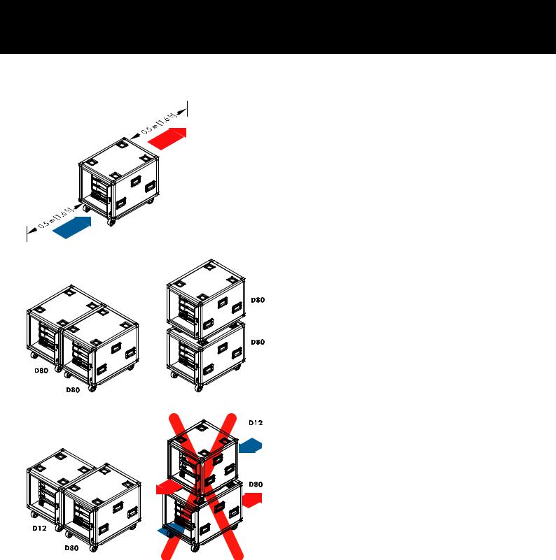
Touring rack assemblies
When using touring rack assemblies such as the d&b Z5330 D80 Touring rack assembly or any other touring rack containing D80 amplifiers, make sure to provide sufficient space of 0.5 m (1.6 ft) at the front and rear of the touring rack to ensure adequate cooling airflow.
D80 Touring rack assemblies can be positioned side by side or stacked.
When combining the Z5330 D80 Touring rack assembly with the Z5310 D12 Touring rack assembly or any other rack assembly that produces an opposing airflow, observe the following restrictions:
– D12/D80 Touring rack assemblies can be positioned side by side.
– Do not stack D80 and D12 Touring racks or any other rack assemblies with opposing airflow.
d&b D80 Manual 1.9 en |
13 |

4.3. Connections
4.3.1. Mains connection
WARNING!
Potential risk of electric shock.
The device is a protective class 1 unit. A missing earth (ground) contact may cause dangerous voltages in the housing and controls and may lead to electric shock.
– Connect the unit to mains power supplies with protective earth only.
– If there is any sign of obvious damage to the power cord and/or mains connector, do not use the power cord and replace it before further use.
– Please ensure the mains connector is accessible at any time to disconnect the unit in case of malfunction or danger.
If the mains plug is not readily accessible due to mounting in a 19" rack, then the mains plug for the entire rack must be readily accessible.
– Do not connect or disconnect the powerCON® mains connector under load or live.
14 |
d&b D80 Manual 1.9 en |

NOTICE!
Due to the high power capability of the device, only operate one device per phase conductor.
Please also refer to Þ Chapter 12.1. "Power supply" on page 68, following Þ Chapter 12.1.5. "Mains supply requirements" on page 69.
Mains voltage |
Frequency |
Current |
100/120 V |
50/60 Hz |
30 A |
230/240 V |
50/60 Hz |
15 - 16 A |
Before connecting the device to mains voltage, check that the mains voltage and frequency correspond to the specifications on the rating label next to the mains connector socket on the rear panel of the unit.
A powerCON-HC® mains connector socket [1] is fitted on the rear panel and an appropriate power cord [2] is supplied.
|
|
|
|
|
|
|
|
|
|
d&b D80 Manual 1.9 en |
15 |
|||

4.3.2. Audio INPUT and LINK connectors
All signal input and link output connectors 1-4 are located on the rear panel.
These can be configured as four analog inputs, two analog and two AES channels or four AES channels (Please refer to
Þ Chapter 9.2. "Input" on page 34).
Each input channel can be routed to any of the output channels A to D (Please refer to Þ Chapter 10.6. "Input routing"
on page 56).
Analog INPUT and LINK (A1 - A4)
A 3-pin female XLR input connector is provided for each channel. Wired in parallel is a 3-pin male XLR input link connector used to feed the input signal on to the next device in the signal chain.
Specifications
Pin assignment |
1 = GND, 2 = pos., 3 = neg. |
|
Input impedance |
38 kOhms, electronically balanced |
|
Common mode rejection (CMRR@100 Hz/10 kHz) |
> 70/50 dB |
|
Maximum input level (balanced/unbalanced) |
+25/17 dBu |
|
|
|
+27 dBu @ 0 dBFS |
LINK analog (A1 - A4) |
|
3 pin XLR male |
|
|
parallel to input |
Digital INPUT and LINK (D1/2 - D3/4)
The input connectors 2 (D1/2) and 4 (D3/4) can be configured as AES/EBU (AES 3) inputs individually.
Note: When configuring the digital inputs, the remaining input and link output connectors 1 (A1) and/or 3 (A3) are disabled.
The corresponding digital LINK output (2/4) can be used to feed a refreshed input signal to the next device in the signal chain. The signal shape (the rising and falling edges of the signal) and level are refreshed with an analog buffer amplifier.
A power fail relay is incorporated to prevent interruption of the signal chain should there be a power failure. In this situation, the digital input signal bypasses the analog buffer amplifier and is routed directly to the LINK output.
Specifications
Pin assignment |
1 = GND, 2 = AES Signal, 3 = AES Signal |
Input impedance |
110 ohms, transformer balanced |
Sampling |
48 / 96 kHz / 2 Ch/n |
Synchronization |
Word-Sync: PLL-locked to source (slave mode) |
LINK digital (Output) |
3-pin XLR male |
|
electronically balanced |
|
analog signal buffering (refresh) |
|
Power Fail Relay (Bypass) |
16 |
d&b D80 Manual 1.9 en |

4.3.3. Output connectors
WARNING!
Potential risk of electric shock.
The amplifier output pins can carry dangerous voltages.
– Only use isolated loudspeaker cables with correctly fitted connectors.
– Never connect an amplifier output pin to any other input or output connector pin or protective earth (ground).
SPEAKER OUTPUTS
Depending on the chosen output option, the amplifier is supplied with four NL4 or EP5 output connectors, one for each amplifier output channel.
Depending on the output mode selected, the appropriate pin assignment of the relevant output connectors is set automatically.
Note: A detailed description of the applicable output modes and how to configure the appropriate output mode is given in Þ Chapter 9.3.1. "Output mode" on page 37.
For further information regarding the applicable output modes for each loudspeaker system, please refer to the relevant loudspeaker manual.
4 CHANNEL OUTPUT
NOTICE!
The 4 CHANNEL OUTPUT connector is only intended as an interface to a rack panel or to loudspeaker multicores and breakout adapters.
Do not connect any loudspeaker cabinets, neither passive nor active systems, to this connector, otherwise there is a risk of damaging the loudspeaker components or the amplifier.
The centered NL8 connector carries the output signals of all four amplifier channels with the following pin assignment:
1+/— = Channel A pos. / neg. |
2+/— |
= Channel B pos. / neg. |
3+/— = Channel C pos. / neg. |
4+/— |
= Channel D pos. / neg. |
d&b D80 Manual 1.9 en |
17 |

Network topologies
|
|
|
|
|
|
|
|
|
|
|
|
|
|
|
|
|
|
|
|
|
|
|
|
|
|
|
|
|
|
|
|
|
|
|
|
|
|
|
|
|
|
|
|
|
|
|
|
|
|
|
|
|
|
|
|
|
|
|
|
|
|
|
|
|
|
|
|
|
|
|
|
|
|
|
|
|
|
|
|
|
|
|
|
|
|
|
|
|
|
|
|
|
|
|
|
|
|
|
|
|
|
|
|
|
|
|
|
|
|
|
|
|
|
|
|
|
|
|
|
|
|
|
|
|
|
|
|
|
|
|
|
|
|
|
|
|
|
|
|
|
|
|
|
|
|
|
|
|
|
|
|
|
|
|
|
|
|
|
|
|
|
|
|
|
|
|
|
|
|
|
|
|
|
|
|
|
|
|
|
|
|
|
|
|
|
|
|
|
|
|
|
|
|
|
|
|
|
|
|
|
|
|
|
|
|
|
|
|
|
|
|
|
|
|
|
|
|
|
|
|
|
|
|
|
|
|
|
|
|
|
|
|
|
|
|
|
|
|
|
|
|
|
|
|
|
|
|
|
|
|
|
|
|
|
|
|
|
|
|
|
|
|
|
|
|
|
|
|
|
|
|
|
|
|
|
|
|
|
|
|
|
|
|
|
|
|
|
|
|
|
|
|
|
|
|
|
|
|
|
|
|
|
|
|
|
|
|
|
|
|
|
|
|
|
|
|
|
|
|
|
|
|
|
|
|
|
|
|
|
|
|
|
|
|
|
|
|
|
|
|
|
|
|
|
|
|
|
|
|
|
|
|
|
|
|
|
|
|
|
|
|
|
|
|
|
|
|
|
|
|
|
|
|
|
|
|
|
|
|
|
|
|
|
|
|
|
|
|
|
|
|
|
|
|
|
|
|
|
|
|
|
|
|
|
|
|
|
|
|
|
|
|
|
|
|
|
|
|
|
|
|
|
|
|
|
|
|
|
|
|
|
|
|
|
|
|
|
|
|
|
|
|
|
|
|
|
|
|
|
|
|
|
|
|
|
|
|
|
|
|
|
|
|
|
|
|
|
|
|
|
|
|
|
|
|
|
|
|
|
|
|
|
|
|
|
|
|
|
|
|
|
|
|
|
|
|
|
|
|
|
|
|
|
|
|
|
|
|
|
|
|
|
|
|
|
|
|
|
|
|
|
|
|
|
|
|
|
|
|
|
|
|
|
|
|
|
|
|
|
|
|
|
|
|
|
|
|
|
|
|
|
|
|
|
|
|
|
|
|
|
|
|
|
|
|
|
|
|
|
|
|
|
|
|
|
|
|
|
|
|
|
|
|
|
|
|
|
|
|
|
|
|
|
|
|
|
|
|
|
|
|
|
|
|
|
|
|
|
|
|
|
|
|
|
|
|
|
|
|
|
|
|
|
|
|
|
|
|
|
|
|
|
|
|
|
|
|
|
|
|
|
|
|
|
|
|
|
|
|
|
|
|
|
|
|
|
|
|
|
|
|
|
|
|
|
|
|
|
|
|
|
|
|
|
|
|
|
|
|
|
|
|
|
|
|
|
|
|
|
|
|
|
|
|
|
|
|
|
|
|
|
|
|
|
|
|
|
|
|
|
|
|
|
|
|
|
|
|
|
|
|
|
|
|
|
|
|
|
|
|
|
|
|
|
|
|
|
|
|
|
|
|
|
|
|
|
|
|
|
|
|
|
|
|
|
|
|
|
|
|
|
|
|
|
|
|
|
|
|
|
|
|
|
|
|
|
|
|
|
|
|
|
|
|
|
|
|
|
|
|
|
|
|
|
|
|
|
|
|
|
|
|
|
|
|
|
|
|
|
|
|
|
|
|
|
|
|
|
|
|
|
|
|
|
|
|
|
|
|
|
|
|
|
|
|
|
|
|
|
|
|
|
|
|
|
|
|
|
|
|
|
|
|
|
|
|
|
|
|
|
|
|
|
|
|
|
|
|
|
|
|
|
|
Star topology |
|
Daisy chain topology for a |
|||||||||||||||||||||||||||||||||||
|
|
|
|
|
|
|
|
|
|
|
|
|
|
|
|
|
|
|
|
maximum of three devices |
|||||||||||||||||
|
|
|
|
|
|
|
|
|
|
|
|
|
|
|
|
|
|
|
|
|
|
|
|
|
|
|
|
|
|
|
|
|
|
|
|
|
|
4.3.4. ETHERNET (Dual Ethernet port)
A Dual Ethernet port with a built-in 2-port Ethernet switch (10/100 Mbit/peer-to-peer) is provided enabling remote control via Ethernet and allows the following physical network topologies:
–Star topology
Recommended standard,
–Daisy chain topology
For a maximum of three devices,
–or a combination of both topologies.
Note: In a daisy chain topology, if one device fails or is switched off, this also affects all subsequent devices which are then no longer connected to the network either.
A detailed description of remote control via Ethernet is given in the technical information TI 310 (d&b code D5310.EN) which can be downloaded from the d&b website at www.dbaudio.com.
LED indicators
The two LED indicators above the respective connector in use indicate the following states:
Green Illuminates permanently when the device is connected to an active network and flashes as long as a data stream is transmitted.
Yellow – Is off when the speed is 10 Mbit.
–Illuminates permanently when the speed is 100 Mbit.
Combined topology
18 |
d&b D80 Manual 1.9 en |

CAN
CAN network topologies
Daisy chain topology
With R60 USB to CAN interface
4.3.5. CAN (CAN-Bus)
The device is equipped with a 2-wire serial remote control interface carrying the CAN-Bus signals to enable remote control with the d&b R60 USB to CAN or R70 Ethernet to CAN interfaces.
Note: A detailed description of remote control via the d&b Remote network (CAN-Bus) is given in the technical information TI 312 (d&b code D5312.EN) which can be downloaded from the d&b website at www.dbaudio.com.
All pins of both connectors are wired in parallel allowing either to be used as input or output (daisy chaining) or for terminating the CAN-Bus network.
Pin assignment
The pin assignments of both, the RJ 45 sockets and the cable connectors, are shown in the graphic opposite.
Note: The connections for the CAN-Bus are referenced to common ground. The "CAN Ground" is routed via the cable shielding and is hardwired to PE.
Within the CAN-Bus network, shielded cables and shielded RJ 45 connectors (metal housing) must be used while the cable shielding must be connected to both sides.
Combined topology
With R70 Ethernet to CAN interface
d&b D80 Manual 1.9 en |
19 |

4.4. Controls and indicators
4.4.1. Mains power switch
The on/off rotary switch [6] is located on the bottom right of the front panel.
OFF Mains isolation is not provided. The internal power supplies are off but stay connected to the mains.
ON The unit is switched on and ready for operation.
4.4.2. Display - User interface
Operation, configuration and status viewing are all performed via the Display Þ User interface.
The user interface consists of a 3.5" TFT color touch screen [7] with a resolution of 320 x 240 pixels and an additional digital rotary encoder [8].
The resistive touch screen responds to pressure and therefore can be operated by a fingertip, even when wearing gloves, or by an appropriate stylus tip (pen).
NOTICE!
The touch panel utilizes a thin flexible sheet that may be damaged by sharp objects or heavy treatment.
Due to the wide range of functions the user interface is described separately in more detail in Þ Chapter 5. "User interface"
on page 23.
However, both the Standby and Mute functions of the D80 are described in the following two sections.
20 |
d&b D80 Manual 1.9 en |
4.4.3. Standby mode
To switch the device to Standby mode ... :
1. Tap the «Power» button on the top right of the Home screen. A dialog appears allowing you to either select the Back button ( - cancel), «Mute all» or «Standby».
2. Select «Standby».
When the device is in Standby mode, both the «Power» button on the right and the green Power on indicator on the left are switched off. In addition, on the Device view button, Standby flashes alternating with the Device name.
Note: In Standby mode, the user interface of the device is still operable.
3. To repower the unit, tap the «Power» button. Startup time from Standby state is < 1 sec.
The operating state (Standby mode) is stored when the «Power» button is set to "Off" and is restored when the «Power» button is set back to "On" again.
In Standby mode, the main power supply and the power amplifiers are switched off to save energy and the loudspeaker outputs are electronically isolated. The display and controls remain active to allow repowering of the device by remote control or by tapping the «Power» button on the Home screen.
Note: When the device is set to Standby (or the mains power is switched off), the movement of the loudspeaker cones in the connected cabinets is no longer damped by the power amplifier output. This removal of the damping makes them susceptible to excitation by other loudspeakers in the surroundings. Audible resonances may occur, and even absorption of low frequency sound energy as the undamped loudspeakers act like a "bass trap".
To permanently mute single subwoofer cabinets while others are operated at the same time it is therefore preferable to use the Mute function instead of Standby. However, the Standby mode can be useful with mid/high systems as it removes any residual noise from the system.
d&b D80 Manual 1.9 en |
21 |

4.4.4. Mute functions
The D80 provides two mute functions:
– Individual mute buttons for each channel or pair of channels Þ Channel mute,
– and a master mute function Þ «Mute all».
Note: The device stores the setting of the mute buttons when the mains power is switched off or disconnected. When the unit is switched on or reconnected, the mute status will be recalled.
Channel mute
Þ To mute or unmute a single channel or a pair of channels, simply tap the respective Channel mute button.
Þ The Channel mute button displays the mute status of the relevant channel or pair of channels and the loudspeaker setup loaded.
Channel muted |
Channel unmuted |
Master mute («Mute all»)
1. To mute all channels simultaneously, tap the «Power» button on the top right of the Home screen.
Þ A dialog appears allowing you to either select the Back button ( - cancel), «Mute all» or «Standby».
2. Select «Mute all».
Þ To unmute the channels, use the individual Channel mute buttons.
22 |
d&b D80 Manual 1.9 en |

5. User interface
5.1. Operating concept
The operating concept allows different methods of interaction and configuration.
Touch screen in combination with the rotary encoder
This method may preferably be used to define values of input fields such as Gain settings, CPL, Delay or EQ settings.
–Select menus, menu items and/or function elements by tapping the relevant item.
–Enter/edit values by turning the encoder.
–Confirm entered/changed values by tapping the respective item or confirmation button («OK») or pushing the encoder.
Rotary encoder only
This method is mainly intended for users who are familiar with the user interfaces of other d&b amplifiers.
–Select menus, menu items and/or function elements by turning the encoder to move the Position cursor to the relevant item.
–Access the selected item or function element by pushing the encoder.
–Enter/edit values by turning the encoder.
–Confirm entered/changed values or leave Edit mode by pushing the encoder.
Cursor conventions
The graphical user interface features two types of cursors, the Position and the Edit cursors.
Position The Position cursor marks the selected Menu item by cursor a white frame. Depending on the type of screen
item, the Position cursor allows you to either activate a function, navigate through the menu or enter Edit
mode Þ Edit cursor.
Edit |
In Edit mode, the Edit cursor is marked by a yellow |
||
cursor |
frame. Turning the encoder to the right (clockwise) |
||
|
|
|
increases the current value, turning the encoder to |
|
|
|
the left (counterclockwise) decreases it. |
|
|
|
To leave Edit mode press the encoder or simply tap |
|
|
|
the respective Menu item again. The color of the |
|
|
|
frame will change from yellow back to white again |
|
|
|
Þ Position cursor. |
d&b D80 Manual 1.9 en |
23 |

Basic screen layout
a)Home screen
b)Device and Channel setup screens
5.2. Screen layout and conventions
The screen layout is split into two main parts, the Header and the Data sections.
Header The Header (Headline) indicates which screen is currently selected. In the Device and Channel setup screens, the Header allows direct access to the previous screen (Back button -  ) or to the Home screen (Home button -
  ).
).
Data Except for the Home screen, the Data sections of the Channel and Device setup screens are structured in tabs on the right hand side of the screen.
The tabbed structure of the screens allows you to directly access the desired subscreens.
5.3. Screen items and views
This section describes the different menu items, views and function elements characterizing the user interface of the D80.
5.3.1. Function buttons
Properties:
–The top left of the button shows the function name while the bottom right shows the status of the function. In addition, the status is also indicated by colors.
–The function is activated by tapping the button on screen or pushing the encoder.
–Functions buttons can also be combined with navigation buttons.
5.3.2. Navigation buttons Properties:
–The top right of the button shows the navigation symbol ( ).
).
–Open the related subscreen by tapping the button on screen or pushing the encoder.
24 |
d&b D80 Manual 1.9 en |
5.3.3. Input fields
Properties:
– The top left of the button shows the field name while the bottom right shows the value. The value can be edited.
– Select the value by tapping the button on screen or pushing the encoder.
– Edit the value by turning the encoder.
Note: The set value will be applied directly.
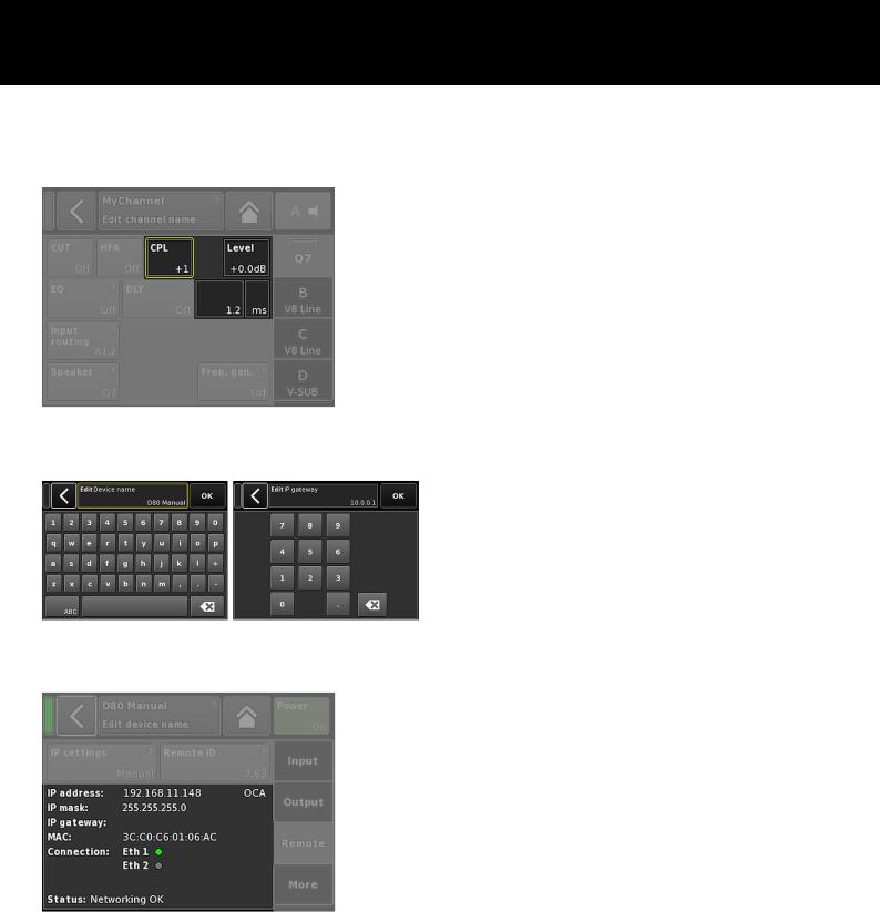
5.3.4. Input masks
Properties:
– Appears automatically anytime you need to enter data to define a particular function. The input mask provides you with an alphanumeric or numeric keypad to enter, for example, a device name or a channel name (alphanumeric keypad) or an IP address (numeric keypad).
– Selection and editing is performed using the touch screen or turning and pushing the encoder.
5.3.5. Information fields
Properties:
Non-selectable/non-editable field for information purposes only.
d&b D80 Manual 1.9 en |
25 |

6. Home screen
From the Home screen, the menu structure of the operating software is divided into two main axes, the Device setup and the Channel setup. The navigation buttons allow for direct vertical access to the specific submenus while the tab structure on the right side of each submenu provides a clear horizontal order.
In addition, the Home screen gives direct access to the Remote subscreen.
The Home screen can be accessed from any screen or menu at any level using the Home button ( ).
).
Home screen access chart
Hierarchy level
|
|
|
|
|
|
|
|
|
|
|
|
|
|
|
|
|
|
|
|
|
|
|
|
|
|
|
|
|
|
|
|
|
|
|
|
|
|
|
|
|
|
|
|
|
|
|
|
|
|
|
|
|
|
|
|
|
|
|
|
|
|
|
|
|
|
|
|
|
|
|
|
|
|
|
|
|
|
|
|
|
|
|
|
|
|
|
|
|
|
|
|
|
|
|
|
|
|
|
|
|
|
|
|
|
|
|
|
|
|
|
|
|
|
|
|
|
|
|
|
|
|
|
|
|
|
|
|
|
|
|
|
|
|
|
|
|
|
|
|
|
|
|
|
|
|
|
|
|
|
|
|
|
|
|
|
|
|
|
|
|
|
|
|
|
|
|
|
|
|
|
|
|
|
|
|
|
|
|
|
|
|
|
|
|
|
|
|
|
|
|
|
|
|
|
|
|
|
|
|
|
|
|
|
|
|
|
|
|
|
|
|
|
|
|
|
|
|
|
|
|
|
|
|
|
|
|
|
|
|
|
|
|
|
|
|
|
|
|
|
|
|
|
|
|
|
|
|
|
|
|
|
|
|
|
|
|
|
|
|
|
|
|
|
|
|
|
|
|
|
26 |
|
|
|
|
|
|
|
|
|
|
|
|
|
|
d&b D80 Manual 1.9 en |
||
Loading...