

Page 1

M4DDC
FM - HD
Diversity Delay Level Control
User Manual
Page 2

2"
M4DDC User Manual
Welcome"
Thanks for purchasing the DaySequerra M4DDC FM Digital Radio Receiver. We design and build all of
our DaySequerra products to be completely reliable and easy to use, so you can concentrate on
producing great sounding broadcasts, not struggling with complicated equipment or difficult to use
product manuals.
While the M4DDC has been designed to be straightforward to use, we do suggest that you spend a few
minutes familiarizing yourself with the features and operational functions that are contained in this
manual.
DaySequerra has been building broadcast quality products since 1989. The technology developed for
the M4DDC, and all of our products, has evolved through a process of user feedback, extensive
listening, field-testing and careful refinement.
In the event that you encounter any technical or operational difficulties with this or any DaySequerra
product, please feel free to contact us at 856-719-9900. Our office hours are from 9 to 5 ET, Monday
through Friday. Or you can email your questions to: info@daysequerra.com.
Also, please remember to visit our website www.daysequerra.com for warranty registration and the
latest DaySequerra product information.
We have worked hard to ensure that your DaySequerra M4DDC HD Radio
TM
Receiver will reliably
serve as a flawless link between the transmitter and your monitoring facility, or as the primary
broadcast reference source in your studio.
We sincerely hope our products help you achieve a new level of excellence in your work!
"
"
"
David V. Day
and the DaySequerra Team
Page 3

3"
M4DDC User Manual
Table of Contents
Important Safety Information 4
Service Information 4
Introduction 4
M4DDC Key Features 5
M4DDC Technical Specifications 6
Unpacking and Installing 7
Typical Installation 8
Experiencing TimeLock for the first time 9
Navigating the Tuner 12
Front Panel 12
Rear Panel 14
LCD Display 14
Navigating the WebServer 17
WebServer – Main 18
WebServer – TimeLock 21
WebServer – Level Lock 22
WebServer – Alarms 23
WebServer – System 26
WebServer – Logging 29
WebServer – Inputs 30
Restore Factory Settings 30
Three Year Warranty 31
M4DDC - Features
• Proprietary TimeLockTM Algorithm – Automatically maintains perfect time alignment of
the HD RadioTM MPS and HD-1 audio streams.
• Robust Level-Lock Algorithm – Maintains average audio level differences between the
MPS and HD-1 audio streams to less than 1 dB (content processing dependent).
• Standalone Operation – 1 RU solution includes an off-air AM or FM receiver, DSP-
based TimeLockTM and Level-Lock algorithms and +/- 7.5 seconds audio delay.
Connect a receive antenna along with your MPS and HD-1 streams and your HD
broadcast is automatically aligned.
Page 4

4"
M4DDC User Manual
Important Safety Information
• Indoor use only. Not for use in wet or damp environments.
• Maximum Relative Humidity: <80%
• Class I Equipment (grounded type)
• Electrical rating: 100-120/220-240V~50-60Hz 18W
• Fuse Rating: 2A 250V 20MM
• AC Mains supply voltage fluctuations are not to exceed +10% of the nominal voltage
• Operations temperature range -40°C to 70°C
• Maximum altitude: 3000m (9843ft)
• Equipment suitable for continuous operation
• Weight: 5.4kg (12lbs) equipment only; 8.2kg (18lbs) shipping
Important Note: Please connect your M4DDC to an uninterruptible power supply (UPS) to
provide other protection against power surges and brownouts.
Service Information
The DaySequerra M4DDC contains no user serviceable components inside the unit. Please contact
DaySequerra for repair and upgrade information. In the event that your unit needs to be returned to the
factory, contact us for a return authorization number. The monitor ID and firmware version is
momentarily displayed at start-up for your convenience. Please visit www.daysequerra.com and
register your new M4DDC so we can keep you informed of the latest hardware and software
updates.
Introduction
The DaySequerra M4DDC Diversity Delay Control is a purpose-built, 1 RU, stand-alone AM or FM
solution and runs DaySequerra’s new proprietary TimeLock
TM
algorithm to automatically maintain
perfect time and audio level alignment of the HD Radio
TM
MPS and HD-1 audio streams.
The M4DDC receives the off-air broadcast measures the time difference between the MPS and HD-1
streams, automatically generates correction vectors necessary to compensate for the offset, and
maintains perfect alignment between the two streams.
Please read this manual thoroughly before operating your M4DDC.
"
"
"
"
"
"
"
"
Page 5

5"
M4DDC User Manual
M4DDC Key Features
• Proprietary TimeLock
TM
Algorithm – Automatically maintains perfect time alignment of the HD
Radio
TM
MPS and HD-1 audio streams.
• Robust Level-Lock Algorithm – Maintains average audio level differences between the MPS and
HD-1 audio streams to less than 1 dB (content processing dependent).
• Standalone Operation – 1 RU solution includes an off-air AM or FM receiver, DSP-based
TimeLock
TM
and Level-Lock algorithms and +/- 7.5 second audio delay. Connect a receive
antenna along with your MPS and HD-1 streams and your HD broadcast is automatically
aligned
• Ballgame Mode – Transmitting in HD Radio
TM
“Ballgame Mode” requires that you smoothly build
in and out of MPS delay without annoying listeners or impacting ratings; protecting the integrity
of Arbitron
TM
PPM watermarking during delay builds and exits and keeps the time-based
structure of your Arbitron PPM watermarking safe.
• Booster Sync – Perfect time alignment is critical to keeping main signals in sync with boosters
or other transmitters relaying on the same frequency. The M4DDC precision delay lets you
make manual MPS delay offset adjustments in increments as small as a single sample.
• Built-in Webserver – The M4DDC’s webserver provides complete remote configuration, remote
control and remote Flash-updates over a LAN or WAN using a common web browser.
• Email and Alarms – Get an email alert direct from your M4DDC for loss of TimeLock and LevelLock; rear panel alarm tallies. No PC app is necessary for email functionality.
• TimeLock Logs – TimeLock proof-of-performance log files are automatically uploaded to your
designated FTP site.
• HD Radio
TM
Split-Mode Audio Output – Left Channel: HD-1 with Right Channel: MPS. AES-3
on rear panel XLR and front panel headphone output > 1 W into 8-ohms.
• Audio-Sync Input-Outputs – MPS and HD-1 AES-3 program audio I/O and External Sync Input
on rear panel XLR’s
• AM or FM Antenna Input - F-type antenna connection and sensitive frequency agile AM or FM
tuner for off-air reception. Please specify AM or FM with your order.
• Remote Reset – Hard reset via rear panel GPI; recessed front panel reset.
• Front Panel Lockout – Prevents unauthorized settings changes.
Page 6

6"
M4DDC User Manual
M4DDC Technical Specifications
RF Tuning Range
AM: 520 kHz to 1720 kHz in 9 kHz or 10 kHz increments
FM: 87.9 MHz to 108.1 MHz in 100 KHz or 200 kHz
increments
RF Usable Sensitivity
AM: <20 dBf (-100 dBm) for SNR -20 referenced to 30%
modulation
FM: <15 dBf (-100 dBm) for SNR -30 dB referenced to 100%
modulation
RF Input F-Type 75 ohm
FM: -55 dBm Nominal: -20 dBm Maximum
IF Rejection
FM” > 100 dB for SNR -30 dB
AF Bandwidth
FM: +/- 1 dB, 20 Hz to 20 kHz
FM De-emphasis
50 or 75 uSec
Program Audio I/O
MPS and HD-1 program audio AES-3 Professional, 110-ohm
transformer-isolated on rear panel XLR connectors
Digital Audio Output
Full-time HD RadioTM Split-Mode: Left Channel: HD-1 with
Right Channel: MPS AES-3 Professional, 110-Ohm
transformer-isolated on rear panel XLR connector
0 dBFS <0.005% THD+N
External Sync Input
AES-3 or AES-11 external sync input on rear panel XLR
connector
Headphone Monitor
Full-time HD RadioTM Split-Mode: Left Channel: HD-1 with
Right Channel: MPS 3.5mm front panel TRS connector
Email Alerts and Alarms
For loss of MPS or HD-1 program audio, TimeLock, LevelLock or OFDM HD Radio
TM
Lock. No PC app is necessary
for email functionality. 5 rear panel alarm tallies.
Built-in Webserver
Password-protected webserver for complete remote
configuration, remote control and remote flash-updates over
a LAN or WAN using a common web browser.
Remote Reset
Hard reset via rear panel GPI; recessed front panel reset
AC Power
Auto-sensing 85-264VAC, 47-63Hz input
Environmental
Operating Temperature: +41 to +105 F (+5 to +40 C) Storage
Temperature: -13 to +140 F (-25 to +60 C) Relative Humidity:
Maximum 85%, non-condensing
Dimensions
1 RU EMI-hardened: 19” (482mm) W x 14” (355mm) D x
1.75” (44mm) H
Shipping Weight
12 lbs. (5.4 kg)
Warranty
Three years, limited parts and labor
Page 7

7"
M4DDC User Manual
Unpacking and Installing the M4DDC
Immediately upon receiving your M4DDC, please make a careful inspection for any shipping damage. If
damage is found or suspected, please notify the carrier at once and then contact your dealer." " The
DaySequerra M4DDC is shipped in one carton, which contains: the M4DDC unit, an AC power cable, a
Torx
TM
T-8 L-key and this User Manual.
We strongly encourage you to save the shipping carton and shipping materials supplied with
your M4DDC. They are specially designed to properly protect your M4DDC, and in the event that you
need to return it for service, only these OEM shipping materials can ensure its safe return to our
factory.
We provide a limited 3-year warranty on all of our products, but if you don’t register your unit, it’s hard
for us to contact you when software updates become available. So please take a few minutes to
complete the warranty registration form on our web site, www.daysequerra.com. Thank you!
Rack Mount Installation. The M4DDC chassis has four rack mounting holes in its chassis and has
been designed to fit in a 19” standard 1RU space. Plastic ‘finishing’ washers are recommended to
protect the painted finish around the mounting holes.
Power Connection. The AC power cable supplied with the M4DDC must be connected from the
M4DDC’s IEC320 power entry module to an AC mains outlet with a functional earth ground connection.
The M4DDC has been set at the factory to operate at 120VAC unless otherwise specified on the
shipping carton. The M4DDC export version is configured for 240VAC operation. Please connect your
M4DDC to an uninterruptible power supply (UPS) to protect against power surges and
brownouts.
Antenna Input Connections. Separate 75ohm F-type connector is provided on the M4DDC rear
panel for dedicated FM or AM antenna depending on the model.
Program Audio Input / Output Connections - MPS and HD-1 program audio"AES-3 Professional,
110-ohm transformer-isolated on rear panel XLR connectors"
Ethernet Connection - The M4DDC Ethernet Port offers the use of DaySequerra’s Webserver by
connecting the M4DDC to any networked computer with Internet access. The use of crossover cables
can be used in areas where a network connection is not possible. More information on the Webserver
can be found at the end of this manual. The Ethernet port with the aid of the webserver will keep the
M4DDC up to date on all Firmware upgrades by checking, downloading and installing with the click of
the ‘Check Firmware’ button on the webserver. (An Internet connection must be available for ‘Firmware
Upgrade’ to work. UPON RECEIVING THE UNIT IT IS ENCOURAGED TO ‘CHECK FIRMWARE’
FROM THE WEBSERVER TO BE SURE YOUR M4DDC IS USING THE MOST RECENT FIRMWARE
AVAILABLE.
"
Page 8
8"
M4DDC User Manual
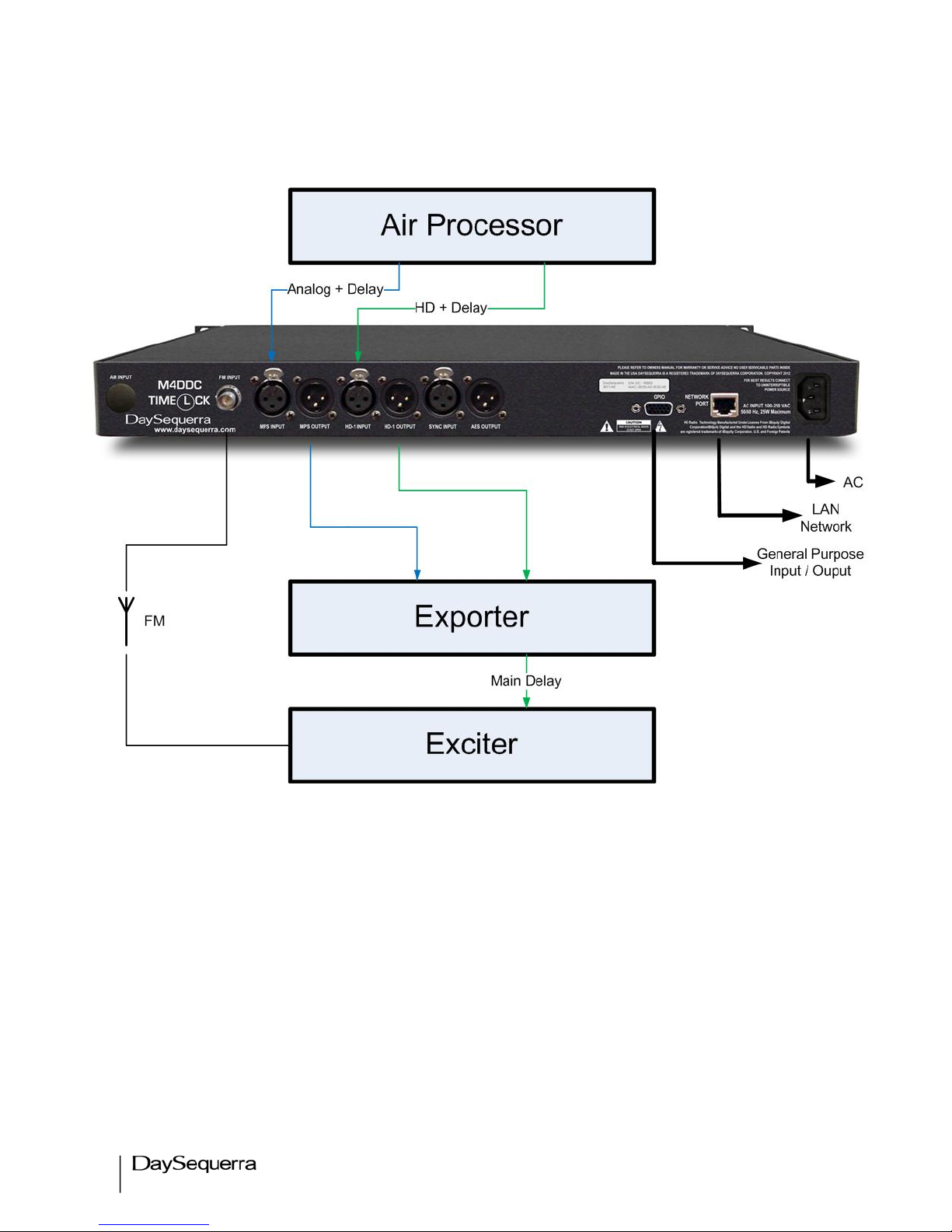
Typical Installation
Figure 1
Page 9

9"
M4DDC User Manual
Experiencing TimeLock™ for the First Time
To fully understand the power of TimeLockTM in action it is highly recommended to experience it with
and without the TimeLockTM Correction algorithm running. First start by disabling TimeLockTM
Correction from the webserver and tune to an un-aligned FM broadcast to hear the misaligned MPS
and HD-1 audio streams.
Uncheck the TimeLockTM Correction box (Figure 2) followed by clicking on Save Settings.
Figure 2
The webserver will then start to ‘Acquire Data’ from the two audio streams and begin correlating them.
In our example below (Figure 3) the Correlation Threshold is set to 70% (Default). Acquired data that
is below this threshold is not correlated and displayed in RED. Acquired data > 70% is considered
correlated and is displayed in GREEN.
Listening to the M4DDC-FM Demo is recommended with headphones. Plug the headphones into the
3.5mm stereo mini-jack connection located on the right side of the M4DDC-FM Demo front panel.
Hearing the misaligned audio streams is very easy using HD Radio Split-Mode audio - HD-1 audio is on
the Left Channel and MPS is on the Right Channel. The TimeLock
TM
webserver display makes
diversity delay measurements simply intuitive. In our example on the next page the MPS is behind by
43.5 MS or +1919 Audio Samples
Figure 3
Uncheck
Adjustable from
70% - 100%
Page 10

10"
M4DDC User Manual
Figure 4
Two audio streams that are only a few MSec out of alignment will sound like an echo with headphones.
Now turn the proprietary TimeLockTM Correction algorithm back on by checking the TimeLockTM
Correction box followed by clicking on Save Settings. TimeLockTM will delay the HD-1 stream until it is
coincident with the Main Program Stream. The audio you now hear becomes sublime. (Figure 5)
Analog lags Digital HD-1
86% Correlation
Page 11

11"
M4DDC User Manual
Figure 5
MPS equals HD-1. There is zero
diversity delay with Timelock
TM
Correction enabled
Page 12
12"
M4DDC User Manual
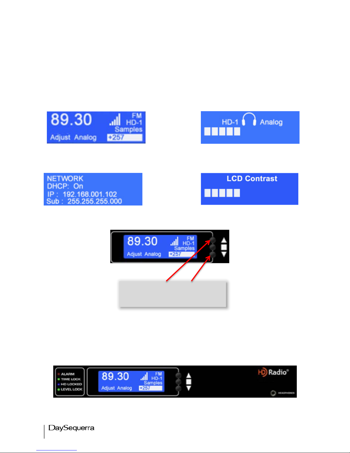
Navigating from the Tuner
The M4DDC employs a simple 3-button user interface. UP or DOWN arrow buttons toggle through
each of the HomeScreens in both directions (Main, Network Settings, Headphone Adjustment, LCD
Contrast Adjustment, and About) Press center ENTER button to Enter / Save.
Main HomeScreen Headphone Adjustment
Network Settings LCD Contrast Adjustment
M4DDC Operating Description - Controls and Indicators
Front Panel
Figure 6
Toggle arrows Up or Down from
the front panel to navigate through
the HomeScreens
Page 13

13"
M4DDC User Manual
Status
• Alarms – Red LED illuminates when an alarm is enabled and flashes red every second when
an alarm condition is active.
•
Time Lock – Green LED illuminates when the TimeLock
TM
Correction function is enabled on
the TimeLockTM tab of the webserver. Disabling this function on the webserver will not align
HD-1 and MPS streams.
•
HD Locked – Blue LED illuminates when tuner has acquired OFDM (orthogonal frequency
division multiplexing) portion of an HD RadioTM signal and digital carrier S/N > 58dB/Hz, thereby
permitting HD Radio
TM
digital audio to be valid. HD is displayed in upper right hand corner of
VFD when tuner has acquired OFDM portion of an HD Radio
TM
signal.
• Level Lock– Green LED illuminates when the Level-Lock Correction function is enabled on
the TimeLock
TM
tab of the webserver. The average audio loudness between the HD RadioTM
MPS analog and HD-1 digital audio streams are then corrected to within 1 dB.
Buttons
•
Up / Down Arrows – Momentary push UP / DOWN from the Main HomeScreen to toggle
each homescreen starting with the Network menu followed by the Headphone Volume, LCD
Contrast, and About menus. Both arrows are used to increase and decrease tuning, volume,
contrast, or change any dynamic field found in the user interface.
•
Center Button – Used to enter SELECTION MODE and Confirm / Save any changed field.
•
Reset Button – Using a paper clip press the reset button hidden behind the front panel to the
right of the center button to power cycle the unit while holding all presets and other settings in
memory.
Headphones
Accepts any headphone or monitor that has a 3.5mm stereo mini-jack connection. Volume control is
software based, from the home screen by pressing either arrow button UP/DN to enter the volume
control menu. Press ENTER to exit and save the desired volume. Headphone output is full time SPLIT
mode (HD-1 in left ear; MPS in right ear).
Page 14
14"
M4DDC User Manual
Rear Panel
Figure 7
• AM or FM Antenna Input - Antenna F-Type, 75-ohm connector. M4DDC-AM and –FM: -55 dBm
Nominal; -20 dBm Maximum
• Digital Audio Output – Full-time HD Radio
TM
Split-Mode: Left Channel: HD-1 with Right Channel:
MPS AES-3 Professional, 110-ohm transformer-isolated on rear panel XLR connector 0 dBFS
<0.005% THD+N
• GPIO – The PLM provides six dry, floating relays with outputs on a rear panel mounted DB15
connector to report selected alarm conditions.
• AES Sync – AES-3 or AES-11 external sync INPUT / OUTPUT allowing the M4DDC to sync to
a master clock source – loop though is provided.
• The M4DDC Ethernet Port offers the use of DaySequerra’s Webserver by connecting the
M4DDC to any networked computer. The use of manual IP with use of crossover cables can be
used in areas where a DHCP enabled network connection is not available. More information on
the Webserver can be found at the end of this manual. The Ethernet port with the aid of the
webserver will keep the M4DDC up to date on all Firmware upgrades by checking, downloading
and installing with the click of the ‘Check Firmware’ button on the webserver. (A network
Internet connection must be available to successfully upgrade the firmware.)
• AC Power - Auto-sensing 85-264VAC, 47-63Hz input.
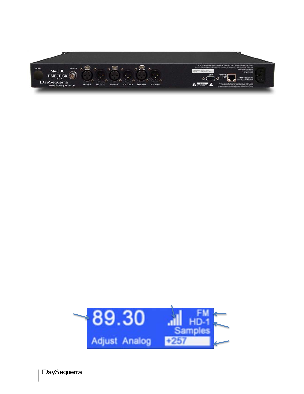
Front Panel LCD - HomeScreens
Main
2.
Figure 8
1.
3.
4.
5.
Page 15

15"
M4DDC User Manual
1. Tuner Frequency – Selects manual AM and FM tuning with UP and DN controls from the
front panel press the center ENTER button then use the arrow button to tune the FM dial. Press
ENTER again or wait 15 seconds for the tuner to timeout and lock on the frequency.
2. SNR Indicator – Strength bars are displayed indicating the CdNo carrier to noise. (Digital
only)
3. Band Indicator – READ-ONLY
4. HD Indicator – Displays HD-1 when the tuner is locked on HD-1. READ-ONLY
5. Diversity Delay Adjustment – Indicates in samples the amount diversity delay that is
required for alignment of the Analog and HD-1 streams. A positive integer indicates that Analog
is lagging behind digital and a negative integer indicates it is ahead of HD-1
Network
Figure 9
By Default DHCP is enabled. Disabling DHCP allows the users to manually enter an IP address,
subnet and gateway IP.
Use the Arrow buttons to toggle up / dn until the Network menu. Then press the center ENTER
button to toggle the arrow selection mode and use the arrow buttons to navigate up or down. Press
ENTER again to make changes. Enable / disable DHCP or change the IP, Subnet, and gateway.
Press enter to toggle to the next field until complete.
Select DONE (top right of LCD) to save and exit this menu. Any changes to this menu will require
the tuner to reboot for the new settings to load.
Headphones
Figure 10
Use the Arrow buttons to toggle up / dn until the Headphone setting. Then press the center ENTER
button to change the volume. Up / Dn arrow control the headphone volume louder and softer. Full time
Page 16

16"
M4DDC User Manual
SPLIT mode is heard though the headphone monitor. Left ear – HD-1; right ear – Analog. Press
ENTER again to save and exit or wait 15 seconds for the menu to timeout.
LCD Contrast
Figure 11
Use the arrow buttons to toggle up / dn until the LCD Contrast setting. Then press the center ENTER
button to change the volume. Up / Dn arrow controls the LCD Contrast. Press ENTER again to save
and exit or wait 15 seconds for the menu to timeout.
About
Figure 12
READ-ONLY - Displays the current HD Radio
TM
, DSP, and UI firmware.
Page 17

17"
M4DDC User Manual
Navigating the Webserver
Start by navigating to the Network menu found in the tuners user interface to find or set the IP address.
In the example below the DHCP router has assigned 192.168.001.102 to the M4DDC. Using a
computer on the same LAN, open up any web browser and type the IP address in the URL to open the
webserver.
Click on any of the seven tabs found at the top to set and control the M4DDC.
Figure 13
Page 18

18"
M4DDC User Manual
Webserver - Main Tab
TimeLock Processing data displays
HD-1 fixed in time relative to Analog.
Both pre and post correction
processing are expressed in samples
and Msec along with audio phase.
Network time displayed next to Clock
is retrieved from an NTP server
Tuning buttons and
frequency
HD Lock and Carrier to
Noise indicator
TimeLock and Level Lock Settings
window
• Correction Threshold range
40% - 100%
• TimeLock and Level Lock
correction are unavailable until
HD Lock is acquired and
correction threshold is greater
than the set %
Page 19

19"
M4DDC User Manual
HD Lock is required for the M4DDC to correlate the Main Program – Analog and HD-1 Digital audio
streams. The HD Radio
TM
icon at the top of this screen acts as an HD Lock indicator. If this is not
present the M4DDC has not acquired HD Lock and cannot build a correlation.
TimeLock Processing Window
TimeLock
TM
processing data is displayed in a RED font if HD-1 or MPS input is NOT present or if the
TimeLock algorithm hasn’t built a correlation between Analog and Digital that is greater than the user
set correlation threshold. Once both conditions are valid the font will turn GREEN indicating that
TimeLock Correction located within TimeLock / Level Lock Settings (no longer shaded out) is available
now.
Data is expressed in samples and time (Msec) for both pre and post correction. If TimeLock Correction
is not enabled the post processing data will read N/A. Audio phase is either ‘IN’ or ‘Out’. Post
processing will display N/A if Audio Phase Correction is disabled.
Figure 14
The slide graph represents HD-1 fixed in time while the Analog stream is measured drifting ahead or
behind HD-1. The Analog slide marker is represented in a GREEN in our example above. This
indicates that a correlation was built that is equal to or higher than the set Correlation Threshold. Any
correlation that is lower than this set amount will be indicated in RED Time moves from right to left.
The red or green Analog marker will drift ahead (left) or behind (right) of the HD-1 stream. Left
indicates that the Analog stream is ahead of HD-1 and is represented by (-) negative samples. Right
indicates Analog is behind HD-1 and is represented by (+) samples. A messages is displayed above
the slide graph at all times explaining how many samples are required to adjust the Analog stream until
the diversity delay is zero.
Time
Message indicating the adjustments
necessary to align both audio streams
to equal zero diversity delay.
Page 20

20"
M4DDC User Manual
TimeLockTM / Level Lock Settings Window
There are several factors that may affect the Analog:Digital correlation. Different genres of music and
the method of processing the audio have proved to yield different correlation results. The user may set
the Correlation Threshold as low or high as desired from 40% to 100%. The default setting is 70%.
Higher correlations will yield more accurate results. Once set this threshold will set the level that at
which Correction becomes available. Changes are not effective until clicking on ‘Save Settings’.
Enable and disable each TimeLock
TM
, Level-Lock, and HD-1 Audio Phase by checking the box next to
each function. To set a know amount of diversity delay check the box next to Analog Manual Offset to
delay the Analog stream by X number of samples. The Master Ramp-In rate is expressed in samples
per second. This sets the amount of samples per second the M4DDC aligns the audio streams to avoid
being noticed by listeners. Selections are 50, 100, 150, 200, and Instant. ‘Instant’ ramp will jump
instantly and may be noticed by listeners depending on the amount diversity delay. Changes are not
effective until clicking on ‘Save Settings’.
Ballgame Mode
Ballgame mode is enabled in the background at all times. A bit in the HD Radio
TM
system will enable
and disable ballgame mode automatically. The ‘Master Ramp-In’ sets the samples per second the
audio will ramp into the live program. Instant will jump directly to the live program. Master Ramp-In
sets how fast or slow the audio streams align. Faster ramping will be noticeable to listeners.
Page 21

21"
M4DDC User Manual
Webserver – TimeLock Tab
The TimeLock
TM
graph displays a running 30-minute window of both pre and post correction. If
TimeLock
TM
correction is not enabled only pre correction is displayed. HD-1 remains fixed in time as
the Analog stream is displayed drifted ahead and behind it. The window resolution is adjustable to
zoom in or out from 600 samples to 600,000 samples
Zoom in or out (samples)
from 600, 6000, 60K, 600K
Window of time is a running
30-minutes. TimeLockTM
window captures and displays
the last 30 minutes of data.
Pre and Post Correction
Page 22

22"
M4DDC User Manual
Webserver – Level Lock Tab
Alarms
Program Loss Monitor – Enabling any alarm will disable tuning, presets and band selection from
the WebServer and M4DDC box User interface by default. To disable this feature unselect ‘Alarms
Lock Tuning’ in General Settings within the Alarms tab of the webserver.
Program Loss Monitor (PLM) Connections – The PLM provides five dry, floating relays with
outputs on a rear panel mounted DB15 connector to report selected alarm conditions, including loss of
RF carrier, program audio, OFDM and HD Lock, and Multicast. Opto-isolated inputs will be triggered by
a voltage of 5VDC. The GPIO Alarm output relays are Normally Open and will close when an alarm is
active. See figure xx for the DB15 pin-outs:
Zoom in or out from
3 dB, 6 dB, 12 dB
Window of time is fixed at 30
minutes. TimeLockTM window
captures and displays the last 30
minutes of data.
Page 23

23"
M4DDC User Manual
Alarm Loss of: No Contact Common
TimeLock
TM
5 10
Correlation 4 9
Level-Lock 3 8
HD Lock 2 7
Empty 1 6
Empty 14 15
Pins not used – (11, 12, 13)
Figure 15
Webserver - Alarms Tab
Email Notifications sets
up to 5 recipients.
Alarms are disabled by
default. Enabling them will
disable tuning from the
webserver and box UI.
Disable ‘Alarms Lock
Tuning’ to tune while
Alarms are enabled.
Page 24

24"
M4DDC User Manual
Each Alarm has a set of conditions for them to become active. Once an alarm is enabled the M4DDC
will continuously monitor and report any conditions that are
Figure 16
In the above example (figure X) the M4DDC will report loss of TimeLock
TM
if MPS and HD-1 drift
beyond 600 samples for 5 seconds or longer. The active alarm is sent to both the GPIO relay and any
email notification recipients if setup.
Figure 17
In the above example (figure X) the M4DDC will report loss of Correlation if it cannot build a correlation
between the MPS and HD-1 streams that is equal to or greater than the set level. 70% is set by default
with a range of 70% to 90%. The alarm will become active if the correlation is below 70% for longer
than the set delay. Delay is set to 15 seconds by default with a range of 5 – 200 seconds. The active
alarm is sent to both the GPIO relay and any email notification recipients if setup.
Figure 18
TimeLock Thresholds
• Delay is set from 5 – 200 seconds.
• Sets the amount of diversity delay in Msec.
• Sets the GPIO relay output
• Enable/Disable. Button turns orange and slides to the
right when enabled.
Thresholds Correlation
• Delay range is 5 – 200 seconds.
• Sets the amount of level in percent
• Sets the GPIO relay output
• Enable/Disable. Button turns orange and slides to the
right when enabled.
Level Lock Thresholds
•
Sets the amount of time the MPS and HD-1 exceed the
set decibels before the alarm triggers. Delay range is
5 – 200 seconds
• Sets how many dB the MPS is above or below HD-1
before the alarm triggers. dB range is 1 – 6 dB
• Weighted Average range 1dB to 6 dB
• Sets the GPIO relay output
• Enable/Disable. Button turns orange and slides to the
right when enabled.
Page 25

25"
M4DDC User Manual
Figure 19
General Settings
Alarms Lock Tuning – Enabled by default locks any tuning out of the webserver and front panel of
the unit. When enabled the tuning button are removed from the webserver when any alarm is enabled.
Disabling ‘Alarms Lock Tuning’ allows tuning while Alarms are enabled.
Email Notifications Settings - configures the M4DDC for email alerts when Alarm conditions
become active. This feature is set to disable by default. Slide the switch to the left indicated in orange
to enable. Entering the SMTP IP, Port, User Name, Password, Sender, and Receiver is required. Click
‘Save’ when finished. *Password is case sensitive alphanumeric. No spaces or symbols may be used.
Pressing ‘Test’ will send a test email to be sure it is configured properly. SSL encrypted logins are
currently unavailable – coming soon in a future firmware release.
Figure 20
HD Lock Loss Thresholds
• Sets the amount of time in seconds without HD
Lock before the HD Lock Loss alarm trips.
• Sets the GPIO relay output
•
Enable/Disable. Button turns orange and slides to
the right when enabled.
Email Notifications
• Disabled by default. Settings fields are disabled until
email notifications is turned on.
• SMTP IP, Port #, User Name, Password, and Sender
• ‘Recipients’ opens up another window (Figure xx)
allowing up to 5 email addresses to be notified at once.
Click ‘SAVE’ or ‘Cancel’ to exit back to the previous
screen.
• Click ‘Save’ to record all settings. Email notifications will
not be set until saved. Use the ‘Test’ button to verify that
the settings are correct by sending a test email.
Page 26

26"
M4DDC User Manual
Figure 21
Webserver – System Tab
Email Recipients
• Up to 5 email address may be used
for email alerts.
• Click ‘Save’ to save and exit or
‘Cancel’ to exit to the previous menu
without saving
Private FTP and Network settings.
Set any common name
for the M4DDC; Pulldown menu selects
from a list of available
Audio Monitors.
About displays S/N
and the current
firmware versions
for the UI and DSP.
Firmware updates, NTP
settings, user guide
download, and other
settings found here.
Page 27

27"
M4DDC User Manual
Private FTP
Private FTP points the M4DDC toward a private FTP site, bypassing DaySequerra’s public FTP used
for updates. Switch the ‘Enable Private FTP’ slider ‘ON’ and enter the private FTP credentials in each
field followed by clicking ‘Save’. Enabling this feature will keep the M4DDC from downloading or
checking for updates directly from DaySequerra. By doing this the M4DDC will not know when new
updates are pushed to the public FTP site by DaySequerra. Please notify DaySequerra so future
firmware updates are sent directly to the user in binary form.
Network Settings
Configures all network connections. DHCP is enabled by default. By disabling DHCP a manual IP
Address, IP Subnet, Gateway are able to be set by entering the data in each field followed by ‘Save’.
MAC is read only. After the Network settings are saved the M4DDC will reset itself so the new network
settings are enabled.
Other Settings
• Firmware Updates
o ‘Check for update’ checks DaySequerra’s public update site against the firmware
version that is listed in the ‘ABOUT’ section. If an update is available the option to
download and install will pop-up. Updates are not automatic. If the Firmware is up to
date a message will pop-up displaying the firmware is up to date. Because the updates
are not automatically checked it’s good practice to periodically check for updates by
selecting ‘Check for Update’.
o
Local update allows the user to perform a firmware and webserver update from a local
network drive. Like using a private FTP, it is necessary to notify DaySequerra for the
latest binary firmware. See figure xx.
o
‘Downgrade Firmware’ enables the user to downgrade back to the last stable release
stored on DaySequerra’s FTP site. A pop-up message asks to continue or cancel.
• ‘Reset Unit’ performs a soft reboot of the M4DDC unit.
• An up to date user manual is always available for download by selecting ‘Download Manual’.
The webserver will be redirected to DaySequerra’s website www.daysequerra.com. Navigate to
/Broadcast Radio/HD RadioTM TimeLockTM /M4DDC TimeLockTM. Click on ‘Manual’ and
‘Download PDF’
• About – Read-Only
o Box ID – M4DDC
o Serial # - Displays the unit serial number
o Firmware Version – Displays the firmware version running on the main processor
and DSP with build numbers and dates.
Page 28
28"
M4DDC User Manual
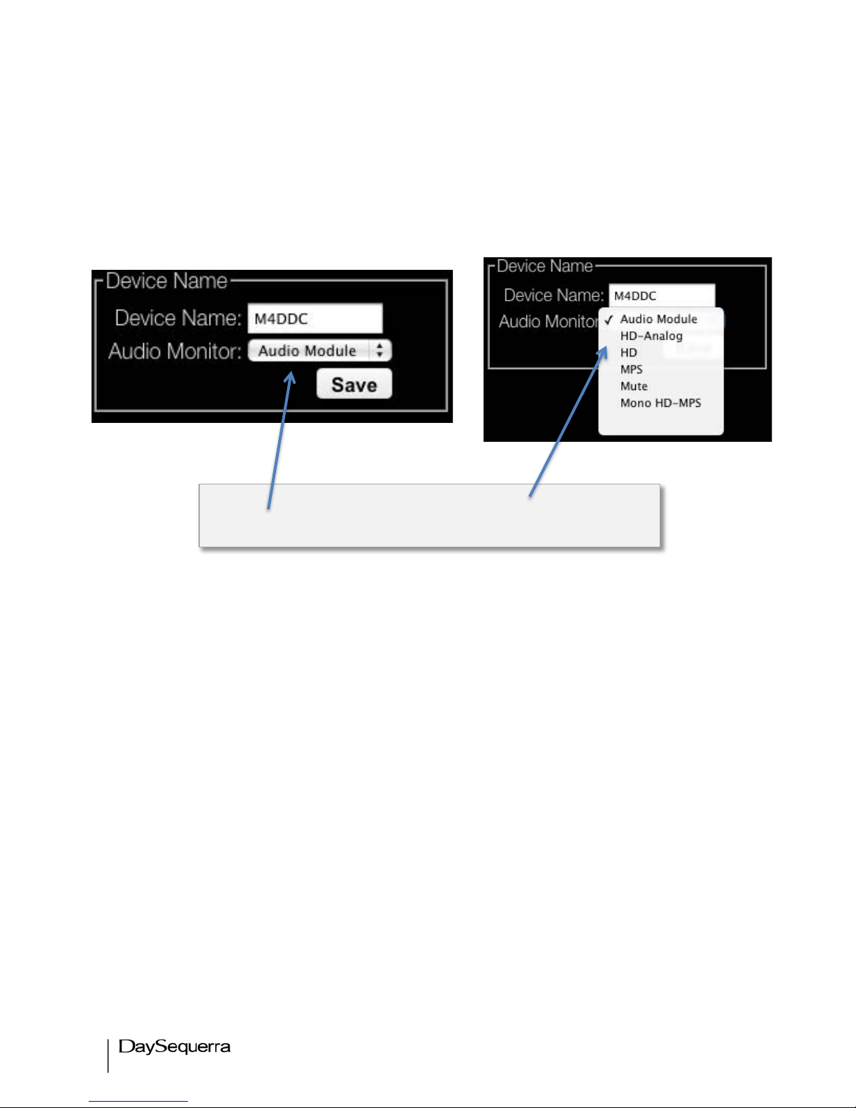
Device Name
Sets a common name for the M4DDC. Using a common name allows users to quickly process alarms
when emails are sent to recipients with multiple units on a network
Audio Monitor
Sets the audio path for monitoring though the front panel headphone jack.
Set Audio Monitor for headphones Pull Down Menu
Page 29

29"
M4DDC User Manual
Webserver – Logging Tab
A log of TimeLockTM, Level Lock, Audio Phase, and Alarms may be exported in .csv format to an FTP
site for download. Data is only logged if it crosses beyond the threshold limits that are set in the ‘Log
Threshold’. Audio Phase and Alarms are always logged and do not have a threshold. Log categories
can be selectively enabled and disabled. Data is stored in a buffer until the set limit (KB) is reached.
The buffer will then upload the log to the defined FTP ‘Log Directory’. The unit will not log data unless
the Log Directory is enabled. An ‘Upload Log Now’ button is available to quickly upload any data that is
stored in the buffer to the directory. Each time this action is performed the log starts over. Logs are
saved with a timestamp, Device name and serial number.
Example of Log Condition > Enable - TimeLock
TM
. Setting the pull-down menus for each as follows:
Samples (pre) 50, Samples (post) 3. Considering the M4DDC is set to correct diversity delay. Pre and
Post correction data is compared to the threshold for each set in the Log Threshold. Pre correction
diversity delay that exceeds 50 samples will be logged. If the delay drifts back and forth from 50 it will
Saves the log to FTP every (x)
KB before clearing the buffer
and starting over again.
TimeLockTM, Level Lock, Audio Phase,
and Alarms must be enabled to log.
TimeLock
TM
and Level Lock will only
log data that reaches the set
Page 30

30"
M4DDC User Manual
log each instance. Post correction diversity delay that drifts beyond 3 samples will be logged. Using
log conditions conserves disk space by only logging data that matters to the user.
Webserver – Inputs Tab
Each input is displayed as a reference to be sure the M4DDC is locked correctly.
Restore Factory Settings
To restore your M4DDC unit back to the original factory settings hold the UP arrow button in while
power cycling the unit. Continue to hold the button in until the message ‘Restoring to factory settings’ is
displayed on the LCD. Be sure the M4DDC is connected to a network with access to the Internet so up
to date support and webserver files are downloaded properly. The original factory default settings will
then be restored.
Displays ‘Locked’ when the M4DDC has acquired an AES lock on a
respective input.
‘Unlocked’ is displayed when there is no AES lock present.
Page 31

31"
M4DDC User Manual
DaySequerra – Three Year Limited Warranty
DaySequerra warrants this product to be free from defects in materials and workmanship to its original
owner for three (3) years from the date of purchase. DaySequerra will repair or replace such product or
part thereof that upon inspection by DaySequerra, is found to be defective in materials or workmanship.
A Return Authorization Number must be obtained from DaySequerra in advance of return. Call
DaySequerra at (856) 719-9900 to receive the number to display on the outside of your shipping carton.
A written statement with the name, address, and daytime telephone number of the original owner,
together with receipt from the original purchase, and a brief description of any claimed defects, must
accompany all returns. Parts or product for which replacement is made shall become the property of
DaySequerra. The customer shall be responsible for all costs of transportation and insurance to and
from the DaySequerra factory, and all such costs will be prepaid.
DaySequerra shall use reasonable efforts to repair or replace any product covered by this limited
warranty within thirty days of receipt. In the event repair or replacement shall require more than thirty
days, DaySequerra shall notify the customer accordingly. DaySequerra reserves the right to replace
any product that has been discontinued from its product line with a new product of comparable value
and function.
This warranty shall be void in the event a covered product has been damaged, or failure is caused by
or attributable to acts of God, abuse, accident, misuse, improper or abnormal usage, failure to follow
instructions, improper installation or maintenance, alteration, or lightning, power fluctuations and other
incidental or environmental conditions. Further, product malfunction or deterioration due to normal
wear is not covered by this warranty.
DAY SEQUERRA DISCLAIMS ANY WARRANTIES, EXPRESSED OR IMPLIED, WHETHER OF
MERCHANTABILITY OR FITNESS FOR A PARTICULAR USE, EXCEPT AS EXPRESSLY SET FORTH
HEREIN. THE SOLE OBLIGATION OF DAY SEQUERRA UNDER THIS LIMITED WARRANTY SHALL BE TO
REPAIR OR REPLACE THE COVERED PRODUCT, IN ACCORDANCE WITH THE TERMS SET FORTH
HEREIN. DAY SEQUERRA EXPRESSLY DISCLAIMS ANY LOST PROFITS, GENERAL, SPECIAL, INDIRECT
OR CONSEQUENTIAL DAMAGES WHICH MAY RESULT FROM BREACH OF ANY WARRANTY, OR
ARISING OUT OF THE USE OR INABILITY TO USE ANY DAY SEQUERRA PRODUCT.
Some states do not allow the exclusion or limitation of incidental or consequential damages or limitation
on how long an implied warranty lasts, so the above limitations and exclusions may not apply to you.
This warranty gives you specific legal rights, and you may also have other rights that vary from state to
state. DaySequerra reserves the right to modify or discontinue, without prior notice to you, any model
or style product. If warranty problems arise, or if you need assistance in using your product contact:
DaySequerra
154 Cooper Road, Building 902
West Berlin, NJ 08091
856-719-9900 (phone)
856-719-9903 (fax)
For more information, please visit www.daysequerra.com or email us at support@daysequerra.com.
 Loading...