

Page 1
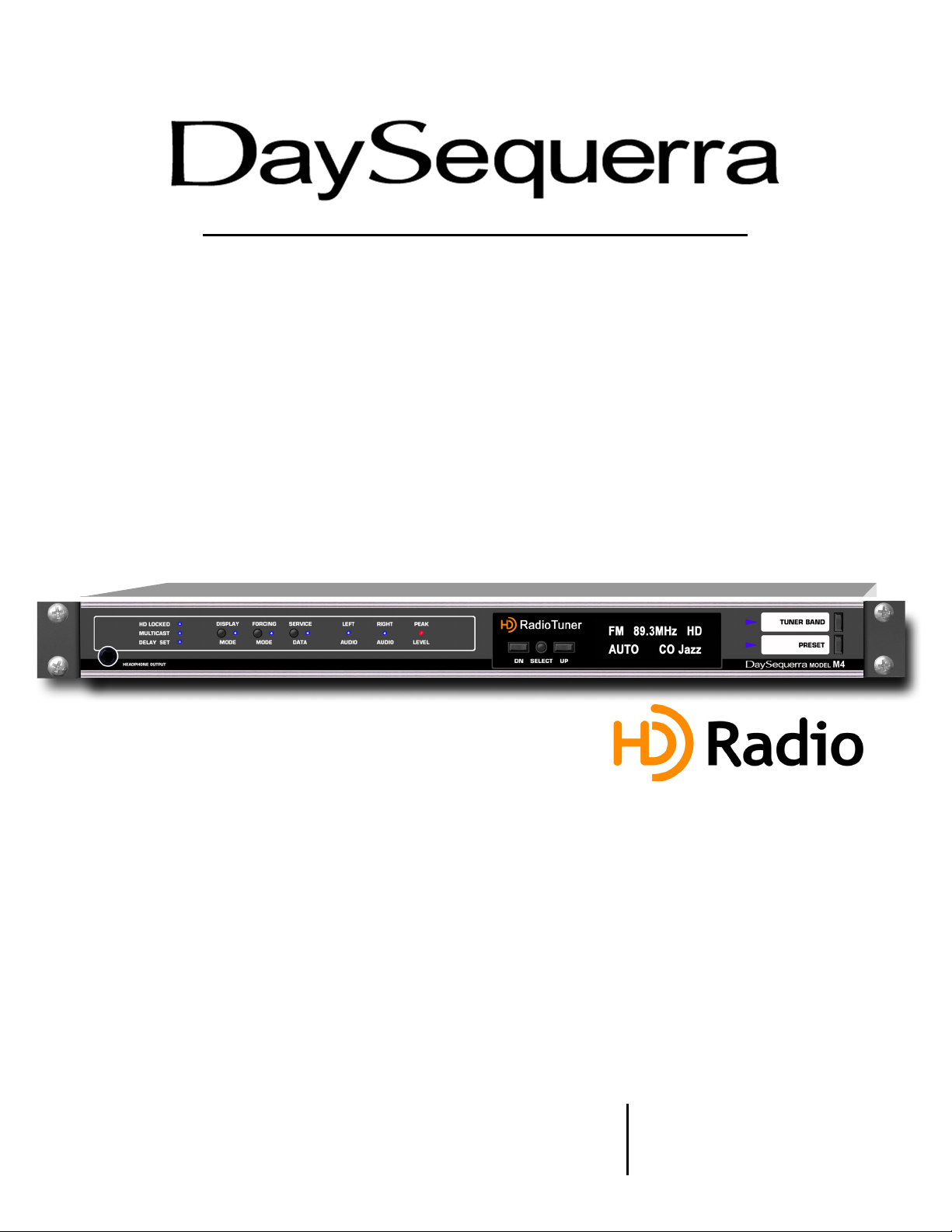
Tuner
U
M4
ser Manual
Page 2

Welcome
y
Thanks for purchasing the DaySequerra M4 HD Radio
DaySequerra products to be completely reliable and easy to use, so you can concentrate on producing
great sounding broadcasts, not struggling with complicated equipment or difficult to use product
manuals.
While the M4 has been designed to be straightforward to use, we do suggest that you spend a few
minutes familiarizing yourself with the features and operational functions that are contained in this
manual.
DaySequerra has been building broadcast quality products since 1989. The technology developed for
the M4, and all of our products, has evolved through a process of user feedback, extensive listening,
field-testing and careful refinement.
In the event that you encounter any technical or operational difficulties with this or any DaySequerra
product, please feel free to contact us at 856-719-9900. Our office hours are from 9 to 5, Monday
through Friday, ET. Or you can email your questions to: info@daysequerra.com
Also, please remember to visit our website www.daysequerra.com for warranty registration and the
latest DaySequerra product information.
We have worked hard to ensure that your DaySequerra M4 will reliably serve as a useful link between
your source material and your broadcasts.
We sincerely hope our products help you achieve a new level of excellence in your work!
David V. Day
and the DaySequerra Team
TM
Tuner. We design and build all of our
2
| | | | |
Day Sequerra 154 Cooper Rd. S902 W. Berlin, NJ 08091 Voice 856-719-9900 Facsimile 856-719-9903 www.daysequerra.com
M4 User Manual
An Group Compan
Page 3

Table of Contents
A
A
Important Safety Information 4
Service Information 4
Introduction 4
M4 Key Features 5
M4 Technical Specifications 5
Unpacking and Installing 6
Front Panel Controls and Indicators 6
M4 Operating Description 7
Sample VFD Displays 10
Three Year Warranty 11
• Eliminated “Standby at Turn-on” feature
M4 Firmware v4.0.5 - New Features
• Number of AM and FM Presets doubled from 10 to 20 for each band
• Capability to store Multicast stations as FM Presets
• Multicast Set feature to keep tuner continuously monitoring selected SPS channel
• SPS PSD patch addresses importer cross-porting
• New “Scrolling Data” mode sequentially displays each MPS and SPS PAD field
• Improved Tuning and Preset scanning speed
• Redesigned user interface for MPS, SPS and Forced Analog modes
• New DATA – DISPLAY menu for enabling Audio Muting and Scrolling Data modes
ll rights reserved ATI Group Inc. Copyright 2006.
ll logos and trademark used herein are the property of their respective owners.
Specifications subject to change.
M4.0 Revision G.
M4 User Manual
3
Page 4

Important Safety Information
• Indoor use only. Not for use in wet or damp environments.
• Maximum Relative Humidity: <80%
• Class I Equipment (grounded type)
• Electrical rating: 100-120/220-240V~50-60Hz 18W
• Fuse Rating: 2A 250V 20MM
• AC Mains supply voltage fluctuations are not to exceed +
10% of the nominal voltage
• Operations temperature range -40°C to 70°C
• Maximum altitude: 3000m (9843ft)
• Equipment suitable for continuous operation
• Weight: 2.9kg (6.5lbs) equipment only; 5.4kg (12lbs) shipping
Important Note: Please connect your M4 to an uninterruptible power supply (UPS) to provide
other protection against power surges and brownouts.
Service Information
The DaySequerra M4 contains no user serviceable components inside the unit. Please contact
DaySequerra for repair and upgrade information. In the event that your unit needs to be returned to the
factory, contact us for a return authorization number. The tuner ID and firmware version is momentarily
displayed at tuner start-up for your convenience. Please visit www.daysequerra.com and register
your new M4 so we can keep you informed of the latest hardware and software updates.
Introduction
The DaySequerra M4 HD Radio
available with built-in multicast capability. The M4 has been designed as the benchmark in sensitivity
(< 5.0dBf in FM) and reliability, and at the same time delivers the highest quality, accurate monitoring of
existing analog and HD Radio
>90dB for HD Radio
TM
FM signals).
Just like its larger sibling, the DaySequerra M2.0, the M4’s ultra low noise RF front-end with built-in
preselector and double-balanced mixer, low-jitter DAC and Class-A biased audio outputs provide the
highest fidelity reception and demodulation of HD Radio
applicable data (PAD) for MPS and SPS multicast signals.
Its robust, modular architecture ensures that the M4 will never become obsolete. The rugged M4
chassis houses dedicated hardware RF, audio and power supply modules that, along with firmware
updates via flash programmable memory, completely anticipates the growth of new HD Radio
services and programming. This design approach along with our product update program ensures that
a broadcaster’s investment in a DaySequerra product will continue to pay off well into the future.
Please read this manual thoroughly before operating your M4.
TM
Tuner is the first “Tomorrow Radio Ready” broadcast quality tuner
TM
AM and FM broadcast signals (THD+N <.005% with stereo separation
TM
programs, including display of program
TM
4
M4 User Manual
Page 5

M4 Key Features
SEPARATE AM AND FM ANTENNA INPUTS – Industry standard 75ohm “F” connectors
STEREO ANALOG OUTPUTS – Balanced (+4dBm) for 100% analog modulation
TM
SPDIF DIGITAL AUDIO OUTPUT – 110ohm transformer isolated for HD Radio
broadcast audio
IEC320 POWER INLET – Integrated fuse holder on rear panel
SYNTHESIZED, PUSHBUTTON TUNING – AM and FM bands including multicast channels
VACUUM FLORESCENT DISPLAY – Multi-function VFD for tuner and station status
PRESETS – 10 preset stations for each AM and FM band
LEFT AND RIGHT AUDIO LEDS – Audio signal present indication
PEAK LEVEL LED – Flashes red for over +4dBm demodulated audio output (either channel)
TM
HD LOCKED – HD Radio
DELAY BIT – Indicates active analog diversity delay for HD Radio
audio present, indicates digital carrier SN > 58dB/Hz
TM
broadcasts
HEADPHONE OUTPUT – Screwdriver gain control on front panel
TM
D-A SPLIT MODE – HD Radio
time-alignment monitor for analog diversity delay
M4 Technical Specifications
RF TUNING RANGE AM – 520kHz to 1720kHz in 10kHz increments
RF USEABLE SENSITIVITY AM – 5dBf for SNR –20dB referenced to 30% modulation
IF REJECTION AM – greater than 100dB for SNR –20dB
AF BANDWIDTH AM – + 1dB 40Hz to 15kHz
FM – +
AF THD+N < 0.005% (digital audio)
STEREO CHANNEL SEPARATION > 90dB (digital audio)
HD Radio
HD Radio
HD Radio
TM
HYBRID ACQUISITION < 4.5 seconds
TM
BLEND LEVEL ACCURACY < 0.5dB
TM
PAD DATA DISPLAY Station long and short name, program type, song title,
FM – 87.9MHz to 108.1MHz in 200kHz increments
FM – 5dBf for SNR –30dB referenced to 100% modulation
FM – greater than 100dB for SNR –30dB
1dB 20Hz to 20kHz
artist, album, genre and comment fields limited to a total of
1018 bytes per message per iBiquity specifications.
M4 User Manual
5
Page 6

Unpacking and Installing the M4
Immediately upon receiving your M4, please make a careful inspection for any shipping damage. If
damage is found or suspected, please notify the carrier at once and then contact your dealer. The
DaySequerra M4 is shipped in one carton, which contains: the M4 unit, an AC power cable and this
User Manual.
We strongly encourage you to save the shipping carton and shipping materials supplied with your M4.
They are specially designed to properly protect your M4, and in the event that you need to return it for
service, only these OEM shipping materials can ensure its safe return to our factory.
We provide a limited 3-year warranty on all of our products, but if you don’t register your unit, it’s hard
for us to help you if and when help becomes necessary. So please take a few minutes to complete
the warranty registration form on our web site, www.daysequerra.com. Thank you!
Rack Mount Installation. The M4 chassis has four rack mounting holes in its chassis and has been
designed to fit in a 19” standard 1RU space. Plastic ‘finishing’ washers are recommended to protect
the painted finish around the mounting holes.
Power Connection. The AC power cable supplied with M4 must be connected from the M4’s IEC320
power entry module to an AC mains outlet with a functional earth ground connection. The M4 has been
set at the factory to operate at 120VAC unless otherwise specified on the shipping carton. Please
connect your M4 to an uninterruptible power supply (UPS) to protect against power surges and
brownouts.
Audio Output Connections. Balanced analog audio outputs are on 3.5mm Eurostyle (Phoenix)
modular connectors on the M4 rear panel with pin 1 +, pin 2 - and pin 3 GND. Analog audio outputs on
M4X is on XLR connectors with pin 1 GND, pin 2 + and pin 3 -.
The M4 digital audio output is transformer isolated in SPDIF format on a 3.5mm Eurostyle (Phoenix)
modular connector on the rear panel with pin 1 XFMR, pin 2 XFMR and pin 3 GND. Digital audio
output for the M4X is also transformer isolated in SPDIF format but on an XLR connector with pin 1
GND, pin 2 XFMR and pin 3 XFMR.
Front Panel Controls and Indicators
TUNER BAND – Selects manual AM and FM tuning with UP and DN controls. Blue arrow LED
illuminates when mode is active.
PRESETS – Tuner has capability to recall 20 preset or stored AM stations and 20 preset or stored FM
stations including HD Radio
PRESETS mode. UP and DN controls scroll through stored stations. When in PRESETS mode,
second push of PRESETS switch changes tuner band.
UP and DN – For manual AM and FM tuning in TUNER BAND mode and scrolling through PRESETS
in PRESETS mode. Also use to set audio output levels in AM and FM, as described below.
SELECT – Multi-function switch for storing PRESETS and controlling other functions, as described
below.
TM
Multicast or SPS stations. Blue arrow LED illuminates when tuner is in
6
M4 User Manual
Page 7

MODE - SERVICE – Default is Auto mode. Momentary push activates multicast tuning when a
multicast signal is present. Holding switch in for 5 seconds when locked to an HD Radio
TM
station,
forces tuner into Analog mode. Blue arrow LED illuminates only when switch is being pushed, or when
multicast tuning or Analog mode is active. In any active mode, second push of MODE – SERVICE
returns tuner to Auto mode.
FORCING – Activates A-D SPLIT mode for to permit monitoring of HD Radio
TM
analog-to-digital time
alignment. Blue arrow LED illuminates when mode is active.
DATA - DISPLAY and DATA - DISPLAY Menu – Selects PAD data from an HD Radio
be displayed on the second line of the VFD. Momentary push DATA - DISPLAY switch scrolls display
through each HD Radio
5 seconds activates DATA - DISPLAY menu. The menu’s first selection enables or disables “Scrolling
Data” mode when tuner displays each HD Radio
TM
PAD data field, as described below. Holding DATA - DISPLAY switch in for
TM
PAD data field for approximately 5 seconds before
TM
broadcast to
scrolling to the next PAD data field. UP or DN switches toggle the setting; pressing “SELECT” saves
the setting and increments the menu to the next field. The second menu field enables or disables
“Audio Muting”. Next press of “SELECT” saves the setting and exits the menu. Blue arrow LED
illuminates only when mode is active. Default is AUTO mode with station short name to be displayed in
second line of VFD when tuned to an HD Radio
HD LOCKED – Blue LED illuminates when tuner has acquired OFDM portion of an HD Radio
and digital carrier SN > 58dB/Hz, thereby permitting HD Radio
displayed in upper right hand corner of VFD when tuner has acquired OFDM portion of an HD Radio
TM
station.
TM
TM
digital audio to be valid. HD is
signal
TM
signal.
MULTICAST – Blue LED illuminates when tuner has acquired OFDM of an HD Radio
TM
signal and
there is at least one multicast SPS signal present.
DELAY BIT – Blue LED illuminates when tuner has acquired OFDM of an HD Radio
the analog diversity delay is active. The LED is off when there is no delay bit set, i.e. “ball game mode”
meaning that the analog program has not been delayed to be coincident with the HD Radio
TM
MPS signal and
TM
MPS
signal.
LEFT PROGRAM – Blue LED illuminates when Left Program audio is present.
RIGHT PROGRAM – Blue LED illuminates when Right Program audio is present.
PEAK LEVEL – Red LED illuminates when Left or Right Program audio exceeds +4dBm (100%
modulation).
M4 Operating Description
Power-up and Standby. The Power switch is located on the rear panel of the M4; when switched on
the tuner displays the hardware and software version for your M4 to be displayed for 3 seconds on the
M4’s VFD.
In any mode, if the SELECT and DN switches are depressed simultaneously for 5 seconds, tuner goes
into Standby mode with all front panel controls and indicators blanked except for SELECT and UP
M4 User Manual
7
Page 8

switches; the M4’s VFD then indicates the “DaySequerra Standby” message. Holding SELECT
together with UP switch in for 5 seconds when in this Standby mode unblanks all front panel controls
and indicators and returns tuner to normal operation.
In STANDBY or master power (rear panel AC switch) off, last station is displayed and all tuner
control/status returns to its default state.
Front Panel Locked. In any mode, if SELECT and MODE – SERVICE switches are depressed
simultaneously for 5 seconds, tuner goes into Front Panel Locked mode i.e., all front panel controls are
inhibited except for UP and SELECT switches; analog and digital audio outputs continue. VFD
alternates between displaying FRONT PANEL LOCKED and normal display for tuned station.
Momentary simultaneous push of SELECT and UP switches in Front Panel Locked mode unblanks all
front panel controls and indicators, and returns tuner to normal operation. VFD displays “Exiting Front
Panel Locked Mode” message during tuner state transition.
Audio Muting. The M4’s audio output can be set to automatically mute for received signals with signal
strength less than 45dBf. The audio muting can be enabled using the DATA - DISPLAY menu
described above.
Tuner Band Control. TUNER BAND control toggles between manual AM and FM tuning. TUNER
BAND arrow LED illuminates only when mode is active. Audio muting is active while tuning.
Presets Control. In PRESETS tuning mode tuner has ability to store 20 AM stations and 20 FM
stations including FM-HD multicast signals.
Preset stations are stored for recall in positions A1 through A20 and F1 through F20 respectively for
AM and FM bands. PRESETS Arrow LED illuminates when tuner is in PRESETS tuning mode. UP and
DN scroll through the preset stations stored for the band selected. Audio MUTING is active while
scrolling through preset stations. Second momentary push of PRESETS switch changes tuner band.
When tuner has acquired any station and SELECT switch is held for three seconds, tuner enters
PRESETS store mode and PRESETS arrow LED flashes. UP and DN controls then allow user to scroll
through A1 through A20 and F1 through F20 dependant on band. When the desired preset location is
indicated on VFD, next momentary push of SELECT switch stores selected station in that PRESETS
position.
Mode - Service Control. MODE - SERVICE control selects AUTO or ANALOG mode, and activates
multicast tuning when an HD Radio
receive an HD Radio
TM
digital broadcast if one is being transmitted, if not the tuner will receive the
analog broadcast. The MODE - SERVICE LED illuminates when only the mode is active or when the
switch is being pushed. Default mode is AUTO.
When tuned to an HD Radio
TM
broadcast and at least one multicast SPS signal is present, momentarily
depressing the MODE – SERVICE switch selects the multicast tuning mode; use the UP and DN
controls to scroll through the multicast stations available.
When tuned to an HD Radio
seconds, the tuner is forced into ANALOG mode; the audio outputs process only the analog portion of
the HD Radio
TM
broadcast.
TM
multicast signal is present. In the AUTO mode, the tuner will
TM
broadcast and the MODE - SERVICE switch is depressed for 5
8
M4 User Manual
Page 9

Forcing Control. The FORCING control is used to select A-D SPLIT mode, functional with AM or FM
HD Radio
TM
signal. When locked to an HD RadioTM signal, momentary push of FORCING switch puts
tuner in A-D SPLIT mode. In A-D SPLIT mode, the analog audio outputs and headphone jack has
analog audio signal in left ear and digital audio signal in right ear. This mode permits user to monitor
the time-alignment of the HD Radio
TM
broadcast for the correct analog diversity delay. FORCING arrow
LED illuminates when tuner is in FORCING mode. Subsequent momentary push of FORCING switch
turns FORCING mode and FORCING LED off. Default mode is off.
Data – Display. The DATA - DISPLAY control is only functional with HD Radio
DISPLAY arrow LED illuminates when mode is active. DATA - DISPLAY switch selects PAD data from
the current HD Radio
TM
station MPS or multicast signal to be displayed on tuner’s VFD. Momentary
TM
signals. DATA -
push scrolls through each PAD field in the following sequence:
• Station long name
• Station program type
• Song title
• Artist
• Album
• Genre
• Comment
Subsequent momentary push of DATA - DISPLAY switch turns DATA - DISPLAY mode and DATA DISPLAY LED off. VFD display second line scrolls if longer than 16 characters. If there is no data for
the selected field, VFD display “NO” plus the data category e.g. “NO ALBUM DATA.”
Station long name, station short name and program type are processed as an ID3 tag. HD Radio
TM
PAD data, i.e., song title, artist, album, genre and comment fields are limited to 127 bytes each for a
total of 1018 bytes per message per iBiquity specifications. For more information on ID3 tags and PAD
data, please visit www.ibiquity.com and www.id3.org.
UP. Momentary push of UP control tunes frequency up one increment in TUNER BAND mode, when
held for three seconds tunes faster. UP selects next stored preset station in PRESETS mode (no faster
mode, one push per preset). Selects next item in other menus and is used for other functions as
described herein.
DN. Momentary push of DN control tunes frequency down one increment in TUNER BAND mode,
when held for three seconds tunes faster. DN selects next stored preset in PRESETS mode (no faster
mode, one push per preset). Selects next item in other menus and is used for other functions as
described herein.
Select Control. When tuner has acquired any station and SELECT switch is held for three seconds,
tuner goes into PRESETS store mode; PRESETS arrow LED flashes. UP and DN controls then allow
user to scroll through A1 through A20 or F1 through F20, dependant on band. Once user has selected
desired PRESETS position, next momentary push of SELECT switch stores selected station in that
PRESETS position.
Multicast Tuning. When tuned to an HD Radio
TM
broadcast with at least one multicast SPS signal
present, momentarily depressing the MODE – SERVICE switch puts tuner into MULTICAST TUNING
mode. Use the UP and DN controls to scroll through each of the multicast stations available. The
DATA - DISPLAY switch selects PAD data from the tuned multicast broadcast to be displayed on
tuner’s VFD.
M4 User Manual
9
Page 10

Headphones. Recessed screwdriver control adjusts headphone output level on recessed ¼” TRS
jack. Default set at the factory is +4dBm.
Sample VFD Displays
HD Radio
HD Radio
HD Radio
HD Radio
HD Radio
TM
FM - default display for WATT-FM
F M 1 0 8 . 3 H D
A U T O W A T T - F M
TM
AM - WATT-AM stored in preset position A9
A 9 5 3 0 H D
A U T O W A T T - A M
TM
FM - WATT-FM in A-D Split Mode
F M 1 0 8 . 3 H D
A - D S P L I T M O D E
TM
FM - Song title (Nights of Unknown Love)
F M 1 0 8 . 3 H D
N I G H T S O F U N K N O W
TM
FM - Multicast HD-2 channel selected
F M 1 0 8 . 3 H D - 2
S P O R T S
10
M4 User Manual
Page 11

DaySequerra – Three Year Limited Warranty
y
DaySequerra warrants this product to be free from defects in materials and workmanship to its original
owner for three (3) years from the date of purchase. DaySequerra will repair or replace such product or
part thereof, that upon inspection by DaySequerra, is found to be defective in materials or
workmanship.
The Proper Return Authorization Number must be obtained from DaySequerra in advance of return.
Call DaySequerra at (856) 719-9900 to receive the number to display on the outside of your shipping
carton. A written statement with the name, address, and daytime telephone number of the original
owner, together with receipt from the original purchase, and a brief description of any claimed defects,
must accompany all returns. Parts or product for which replacement is made shall become the property
of DaySequerra. The customer shall be responsible for all costs of transportation and insurance to and
from the DaySequerra factory, and all such costs will be prepaid.
DaySequerra shall use reasonable efforts to repair or replace any product covered by this limited
warranty within thirty days of receipt. In the event repair or replacement shall require more than thirty
days, DaySequerra shall notify the customer accordingly. DaySequerra reserves the right to replace
any product that has been discontinued from its product line with a new product of comparable value
and function.
This warranty shall be void in the event a covered product has been damaged, or failure is caused by
or attributable to acts of God, abuse, accident, misuse, improper or abnormal usage, failure to follow
instructions, improper installation or maintenance, alteration, or lightning, power fluctuations and other
incidental or environmental conditions. Further, product malfunction or deterioration due to normal
wear is not covered by this warranty.
DAY SEQUERRA DISCLAIMS ANY WARRANTIES, EXPRESS OR IMPLIED, WHETHER OF
MERCHANTABILITY OR FITNESS FOR A PARTICULAR USE, EXCEPT AS EXPRESSLY SET FORTH
HEREIN. THE SOLE OBLIGATION OF DAY SEQUERRA UNDER THIS LIMITED WARRANTY SHALL BE TO
REPAIR OR REPLACE THE COVERED PRODUCT, IN ACCORDANCE WITH THE TERMS SET FORTH
HEREIN. DAY SEQUERRA EXPRESSLY DISCLAIMS ANY LOST PROFITS, GENERAL, SPECIAL, INDIRECT
OR CONSEQUENTIAL DAMAGES WHICH MAY RESULT FROM BREACH OF ANY WARRANTY, OR
ARISING OUT OF THE USE OR INABILITY TO USE ANY DAY SEQUERRA PRODUCT.
Some states do not allow the exclusion or limitation of incidental or consequential damages or limitation
on how long an implied warranty lasts, so the above limitations and exclusions may not apply to you.
This warranty gives you specific legal rights, and you may also have other rights that vary from state to
state. DaySequerra reserves the right to modify or discontinue, without prior notice to you, any model
or style product. If warranty problems arise, or if you need assistance in using your product contact:
DaySequerra
154 Cooper Road, Suite 902
West Berlin, NJ 08091
856-719-9900 (phone)
856-719-9903 (fax)
For more information, please visit www.daysequerra.com or email us at info@daysequerra.com.
An Group Compan
| | | | |
Day Sequerra 154 Cooper Rd. S902 W. Berlin, NJ 08091 Voice 856-719-9900 Facsimile 856-719-9903 www.daysequerra.com
M4 User Manual
11
 Loading...