

Page 1
PTC-140NDI
NDI PTZ CAMERA
Page 2

Table of Contents
TABLE OF CONTENTS ........................................................................................ 2
FCC COMPLIANCE STATEMENT ......................................................................... 4
WARNINGS AND PRECAUTIONS ........................................................................ 4
WARRANTY ...................................................................................................... 5
STANDARD WARRANTY ............................................................................................. 5
THREE YEAR WARRANTY............................................................................................ 6
DISPOSAL ......................................................................................................... 7
1. PRODUCT OVERVIEW ............................................................................... 8
FEATURES ............................................................................................................... 8
2. LOCATION AND FUNCTION OF PARTS ....................................................... 9
3. BASIC SETUP .......................................................................................... 13
3.1 POWER-ON INITIALIZATION ......................................................................... 13
3.2 VIDEO OUTPUT ......................................................................................... 13
NDI® | HX/DVIP Port ..................................................................................... 13
HDMI Video Output....................................................................................... 15
3G-SDI Video Output ..................................................................................... 15
4. HOW TO USE THE NDI STUDIO MONITOR SOFTWARE ............................. 16
4.1 NDI INTRODUCTION .................................................................................. 16
4.2 HOW TO USE THE NDI STUDIO SOFTWARE (TAKE WINDOWS 10 FOR EXAMPLE) . 16
5. REMOTE CONTROL AND ON-SCREEN MENU ............................................ 20
5.1 REMOTE CONTROL FUNCTIONS .................................................................... 20
5.2 ON-SCREEN MENU ................................................................................... 25
5.3 PROFESSIONAL JARGON EXPLANATIONS OF THE OSD MENU ............................. 34
6. INSTALLATION INSTRUCTIONS ................................................................ 35
7. NETWORK CONNECTION ........................................................................ 39
7.1 DHCP MODE ........................................................................................... 40
7.2 STATIC IP ................................................................................................ 42
7.3 DVIP ...................................................................................................... 42
2
Page 3

8. WEB USER INTERFACE ............................................................................ 46
8.1 PREVIEW ................................................................................................. 46
Control Functions .......................................................................................... 47
Preset ............................................................................................................ 49
8.2 CONFIGURATION ....................................................................................... 50
Audio Configure ............................................................................................ 50
Video Configure ............................................................................................ 52
Network Configure ...................................................................................... 104
System Configure ........................................................................................ 109
9. REMOTE CONTROL PORT PINOUTS ....................................................... 113
10. FIRMWARE UPDATE ......................................................................... 115
REQUIREMENTS ................................................................................................... 115
PROCEDURE ........................................................................................................ 115
11. FREQUENTLY-ASKED QUESTIONS ...................................................... 116
12. DIMENSIONS .................................................................................... 118
13. SPECIFICATIONS ............................................................................... 119
SERVICE & SUPPORT ..................................................................................... 124
Disclaimer of Product and Services
The information offered in this instruction manual is intended as a guide only. At
all times, Datavideo Technologies will try to give correct, complete and suitable
information. However, Datavideo Technologies cannot exclude that some
information in this manual, from time to time, may not be correct or may be
incomplete. This manual may contain typing errors, omissions or incorrect
information. Datavideo Technologies always recommend that you double check
the information in this document for accuracy before making any purchase
decision or using the product. Datavideo Technologies is not responsible for any
omissions or errors, or for any subsequent loss or damage caused by using the
information contained within this manual. Further advice on the content of this
manual or on the product can be obtained by contacting your local Datavideo
Office or dealer.
3
Page 4

FCC Compliance Statement
This device complies with part 15 of the FCC rules. Operation is subject to the
following two conditions:
(1) This device may not cause harmful interference, and
(2) This device must accept any interference received, including interference
that may cause undesired operation.
Warnings and Precautions
1. Read all of these warnings and save them for later reference.
2. Follow all warnings and instructions marked on this unit.
3. Unplug this unit from the wall outlet before cleaning. Do not use liquid or
aerosol cleaners. Use a damp cloth for cleaning.
4. Do not use this unit in or near water.
5. Do not place this unit on an unstable cart, stand, or table. The unit may fall,
causing serious damage.
6. Slots and openings on the cabinet top, back, and bottom are provided for
ventilation. To ensure safe and reliable operation of this unit, and to protect
it from overheating, do not block or cover these openings. Do not place this
unit on a bed, sofa, rug, or similar surface, as the ventilation openings on the
bottom of the cabinet will be blocked. This unit should never be placed near
or over a heat register or radiator. This unit should not be placed in a built-in
installation unless proper ventilation is provided.
7. This product should only be operated from the type of power source
indicated on the marking label of the AC adapter. If you are not sure of the
type of power available, consult your Datavideo dealer or your local power
company.
8. Do not allow anything to rest on the power cord. Do not locate this unit
where the power cord will be walked on, rolled over, or otherwise stressed.
9. If an extension cord must be used with this unit, make sure that the total of
the ampere ratings on the products plugged into the extension cord do not
exceed the extension cord’s rating.
4
Page 5

10. Make sure that the total amperes of all the units that are plugged into a
single wall outlet do not exceed 15 amperes.
11. Never push objects of any kind into this unit through the cabinet ventilation
slots, as they may touch dangerous voltage points or short out parts that
could result in risk of fire or electric shock. Never spill liquid of any kind onto
or into this unit.
12. Except as specifically explained elsewhere in this manual, do not attempt to
service this product yourself. Opening or removing covers may expose you to
dangerous voltage points or other risks, and will void your warranty. Refer all
service issues to qualified service personnel.
13. Unplug this product from the wall outlet and refer to qualified service
personnel under the following conditions:
a. When the power cord is damaged or frayed;
b. When liquid has spilled into the unit;
c. When the product has been exposed to rain or water;
d. When the product does not operate normally under normal operating
conditions. Adjust only those controls that are covered by the operating
instructions in this manual; improper adjustment of other controls may
result in damage to the unit and may often require extensive work by a
qualified technician to restore the unit to normal operation;
e. When the product has been dropped or the cabinet has been damaged;
f. When the product exhibits a distinct change in performance, indicating a
need for service.
Warranty
Standard Warranty
Datavideo equipment are guaranteed against any manufacturing defects for
one year from the date of purchase.
The original purchase invoice or other documentary evidence should be
supplied at the time of any request for repair under warranty.
The product warranty period begins on the purchase date. If the purchase
date is unknown, the product warranty period begins on the thirtieth day
after shipment from a Datavideo office.
5
Page 6

All non-Datavideo manufactured products (product without Datavideo logo)
have only one year warranty from the date of purchase.
Damage caused by accident, misuse, unauthorized repairs, sand, grit or
water is not covered under warranty.
Viruses and malware infections on the computer systems are not covered
under warranty.
Any errors that are caused by unauthorized third-party software installations,
which are not required by our computer systems, are not covered under
warranty.
All mail or transportation costs including insurance are at the expense of the
owner.
All other claims of any nature are not covered.
All accessories including headphones, cables, and batteries are not covered
under warranty.
Warranty only valid in the country or region of purchase.
Your statutory rights are not affected.
Three Year Warranty
All Datavideo products purchased after July 1st, 2017
are qualified for a free two years extension to the
standard warranty, providing the product is registered
with Datavideo within 30 days of purchase.
Certain parts with limited lifetime expectancy such as LCD panels, DVD drives,
Hard Drive, Solid State Drive, SD Card, USB Thumb Drive, Lighting, Camera
module, PCIe Card are covered for 1 year.
The three-year warranty must be registered on Datavideo's official website
or with your local Datavideo office or one of its authorized distributors within
30 days of purchase.
6
Page 7

Disposal
For EU Customers only - WEEE Marking
This symbol on the product or on its packaging indicates that this
product must not be disposed of with your other household
waste. Instead, it is your responsibility to dispose of your waste
equipment by handing it over to a designated collection point for
the recycling of waste electrical and electronic equipment. The separate
collection and recycling of your waste equipment at the time of disposal will help
to conserve natural resources and ensure that it is recycled in a manner that
protects human health and the environment. For more information about where
you can drop off your waste equipment for recycling, please contact your local
city office, your household waste disposal service or the shop where you
purchased the product.
CE Marking is the symbol as shown on the left of this page. The
letters "CE" are the abbreviation of French phrase "Conformité
Européene" which literally means "European Conformity". The
term initially used was "EC Mark" and it was officially replaced
by "CE Marking" in the Directive 93/68/EEC in 1993. "CE Marking" is now used in
all EU official documents.
7
Page 8

1. Product Overview
The PTC-140NDI is a low-cost SDI/HDMI PTZ camera, which features 20x optical
zoom and 10x digital zoom. The PTC-140NDI is an IP camera as well for
supporting H.264 /H.265 video compression and dual stream output. It features
NDI® | HX, which is the first NDI camera launched by Datavideo.
Features
1/2.8 inch CMOS sensor. Resolution is up to 1920x1080 with frame rate up to
60fps.
Low Noise CMOS effectively ensures high SNR of camera video. Advanced
2D/3D noise reduction technology is also used to further reduce the noise,
while ensuring image sharpness.
Audio Input Interface
Supports AAC, MP3 and G.711A audio coding with sampling frequencies of
16000, 32000, 44100 and 48000.
Supports H.264/H.265 video compressions of resolution up to 1920x1080
with frame rate up to 60fps, AAC, MP3 and G.711A audio compressions and
2-channel 1920x1080p with 30fps video compression.
Supports multiple network protocols such as RTSP and RTMP allowing you to
easily link to any streaming media servers.
Supports Simultaneous Video Outputs by NDI® | HX, 3G SDI and HDMI
interfaces for up to 1080p60 resolution.
8
Page 9
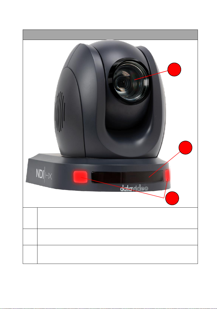
2. Location and Function of Parts
Front of Camera
1
Lens
Built-in 1/2.8” 2.07M Pixel CMOS HD color camera with white balance
control, backlight compensation, automatic gain and etc.
2
Tally LED
Tally lamp will be turned ON upon receiving the ON signal.
3
Sensor for Remote Control
Remote control IR receiver
1 3 2
9
Page 10
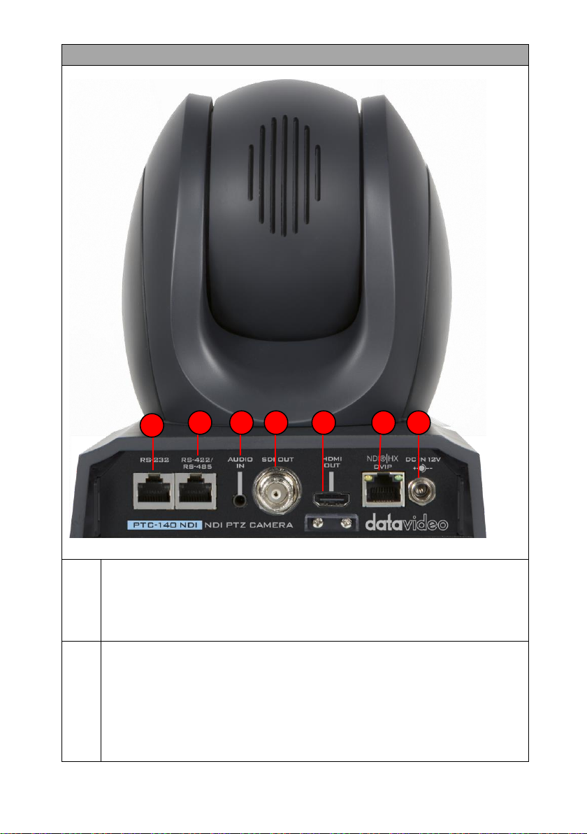
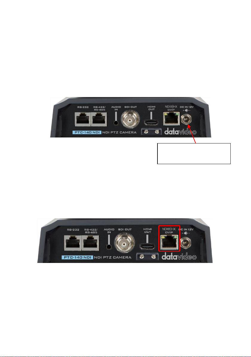
Rear of Camera
1
Power Input
DC in socket connects the supplied 12V PSU. The connection can be
secured by screwing the outer fastening ring of the DC In plug to the
socket.
2
NDI® | HX & DVIP Interface
NDI® | HX interface allows users to connect the PTC-140NDI and a PC to
the RJ-45 Ethernet interfaces of the same router by using an RJ-45
Ethernet cable. Moreover, users can set the PC and the PTC-140NDI
camera in the same local area network for controlling some functions of
the PTC-140NDI camera by NewTek’s “NDI Studio Monitor” software.
The most important benefit that the NDI brings to users is that it allows
1 2 3 4 5 6 7
10
Page 11

the output screen of the PTC-140NDI camera to be auto-recognized by
the NDI compatible receiving devices (e.g. Notebook PC) which are set in
the same local area network.
The DVIP interface allows users to control the PTC-140NDI camera by
the proprietary DVIP protocol which is developed by Datavideo.
3
HDMI OUT
The HDMI OUT allows you to connect an external HDMI monitor via an
HDMI cable.
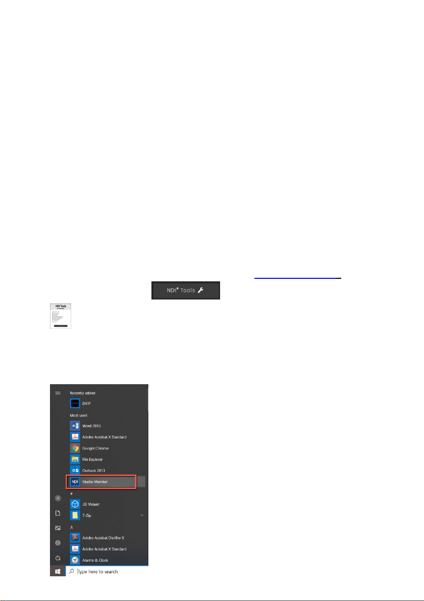
4
3G-SDI OUT
The 3G-SDI OUT allows you to connect an external monitor via an SDI
cable.
5
Audio IN
The 3.5mm audio input receives external audio.
6
RS-422/RS-485 Interface (RJ-45)
The RS-485 interface serves to connect external RS-422/RS-485 devices.
Use an Ethernet cable to connect external RS-422/RS-485 controllers.
See “Section 9 Remote Control Port Pinouts” for making the cable for
the RS-422/RS-485 interface.
Note: To switch between RS-422 and RS-485 communication protocols,
open OSD menu, then go to Setup RS-485/422 in which you will be
allowed to select the appropriate protocol.
7
RS-232 Interface (RJ-45)
The RS-232 interface connects PTC-140NDI to a remote controller or PC
for control purpose. Use an Ethernet cable to connect external RS-232
controllers. See “Section 9 Remote Control Port Pinouts” for making the
cable for the RS-232 interface.
11
Page 12
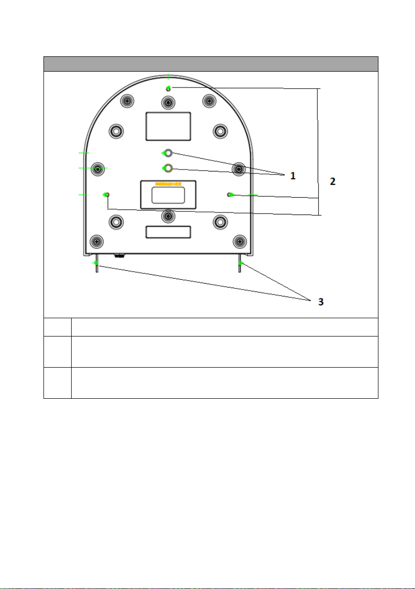
Bottom of Camera
1
Tripod Screw Hole allows the user to mount the camera on the tripod.
2
Screw Hole
Screw holes for ceiling bracket mounting.
3
For Safety Rope
Ties safety rope for fixing the camera to the ceiling.
12
Page 13
3. Basic Setup
Connect the DC 12 V
power adapter
3.1 Power-On Initialization
As shown in the diagram below, after you plug in the power cord, the tally light in
the front will start flashing red and will be OFF as soon as the power-on
initialization is complete. The camera head should be at the HOME position with
the lens facing front. However, if preset 0 is set, it will return to the 0th preset
position.
3.2 Video Output
You are allowed to view the camera video via NDI® | HX/DVIP port, HDMI OUT
and 3G-SDI OUT.
NDI® | HX/DVIP Port
Follow the instructions below to view your video on the web user interface.
Connect the PTC-140NDI camera directly to your PC/Notebook PC
1. Connect the PTC-140NDI to the PC/Notebook using an Ethernet cable.
2. On your PC/Notebook, open the web browser and enter camera’s default IP
address into the address bar.
13
Page 14

Note: The default static IP address is 192.168.5.163
3. On the Login page enter the username and password which are admin/admin
respectively by default.
4. Click into the preview window on which the video will be displayed.
Connect the PTC-140NDI camera to your PC or Notebook PC through a
router
1. Please set the Ethernet IP address of your PC or Notebook PC as 192.168.5.x (x
means 0-255) and then the PC or Notebook PC will be within the same local area
network as the PTC-140 NDI camera.
2. Please use an RJ-45 Ethernet cable to connect from the NDI® | HX/DVIP port
which is located on the rear panel of the PTC-140NDI to the LAN of a router. And
then please use another RJ-45 Ethernet cable to connect from the RJ-45 Ethernet
interface of your PC or Notebook PC to the LAN port of the same router.
3. On your PC/Notebook, open the web browser and enter camera’s default IP
address into the address bar.
Note: PTC-140NDI’s default static IP address is 192.168.5.163
4. On the Login page enter the username and password which are admin/admin
respectively by default.
5. Click into the preview window on which the video will be displayed.
14
Page 15
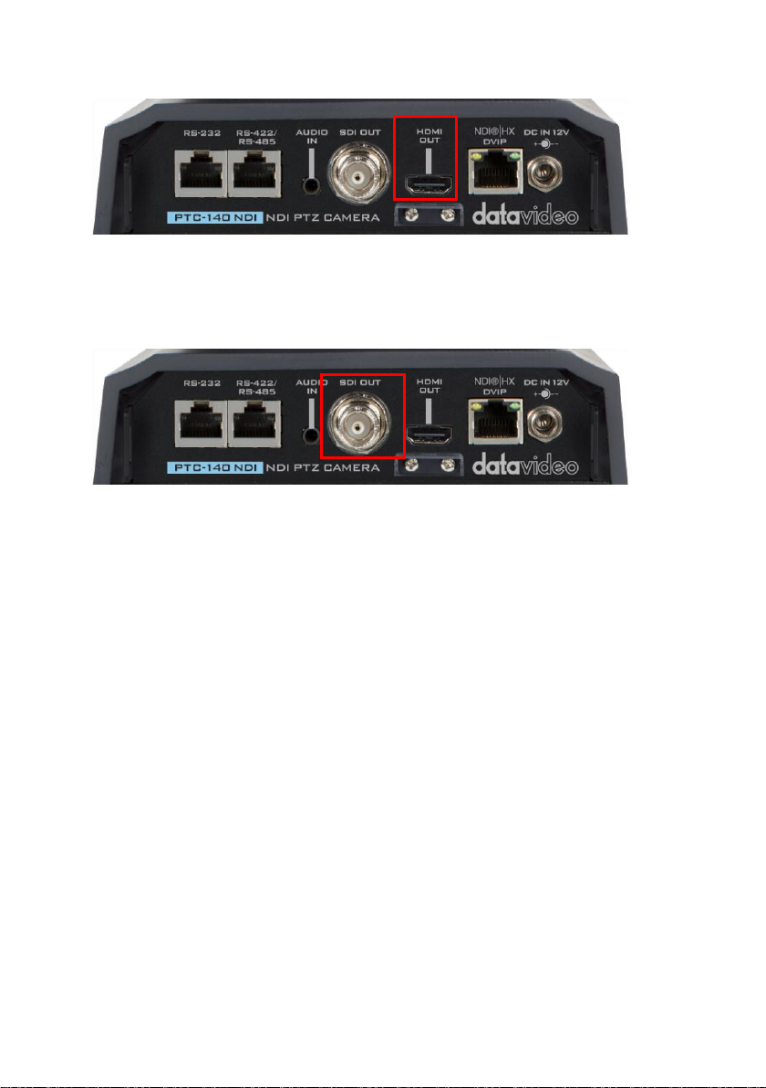
HDMI Video Output
Connect the HDMI OUT to an external connected monitor using an HDMI cable.
3G-SDI Video Output
Connect the SDI OUT to an external connected monitor using an SDI cable.
15
Page 16
4. How to Use the NDI Studio Monitor Software
4.1 NDI Introduction
NDI is an Ethernet-based open video and audio transmission standard. NDI allows
bilateral video and audio signal transmission for devices which are located within
the same Local Area Network. It provides low-latency and real-time features
which make it an ideal solution for the live production application.
4.2 How to Use the NDI Studio Software (Take
Windows 10 for Example)
Please follow following steps for using the NDI Studio Monitor software.
1. At first, please confirm that your PTC-140 NDI camera and your laptop are
connected to a router and they are set in the same Local Area Network.
2. Please connect to NetTek NDI official web page https://www.ndi.tv/, and then
please press “NDI Tools” . After that, please press “Download”
to download the latest version NDI Tools software.
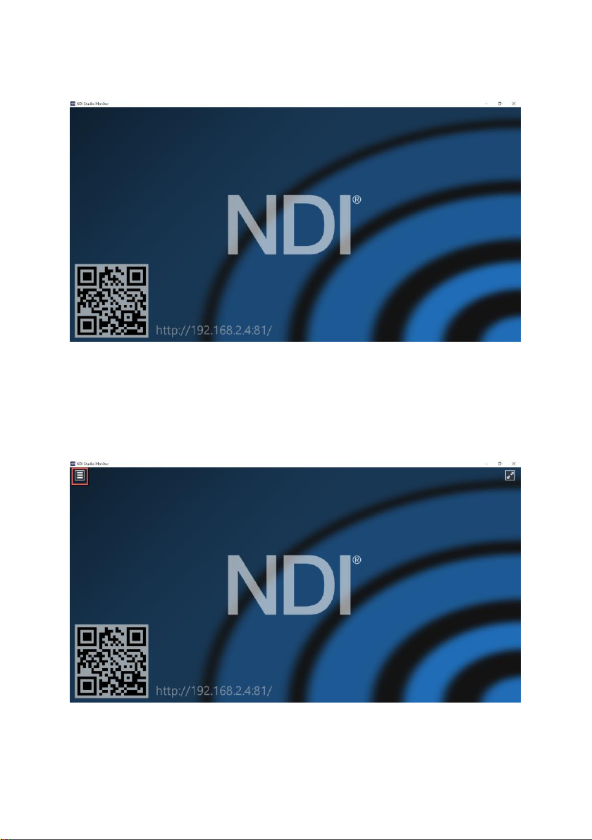
3. After the installation is finished, please press “Studio Monitor” to open the NDI
Studio Monitor software.
16
Page 17
4. After the Studio Monitor Software is launched, its interface will be shown as
following diagram.
5. Please move your mouse cursor to the top-left side and then click the menu
button. After that, you can see the Studio Monitor menu. You can also right-click
on the Studio Monitor interface for showing the menu.
17
Page 18
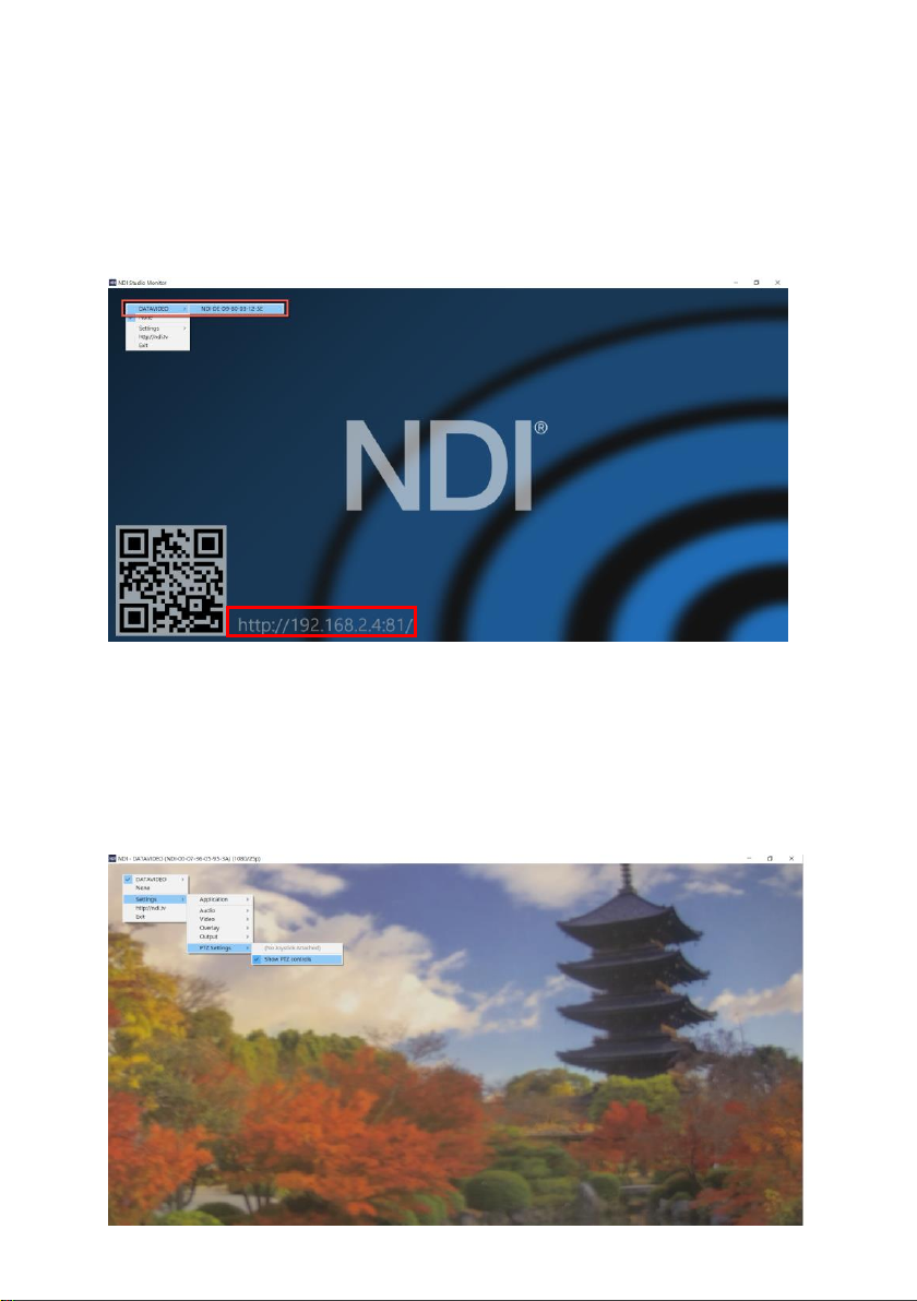
6. From the menu, users can see that the PTC-140NDI camera which is connected
to the same local area network as the Studio Monitor is detected successfully.
Please click it and then users can see the screen which is shot by the PTC140NDI is shown as following diagram. For the device which is connected to
the same local area network, users can enter the IP address into the address
bar of the web browser for connecting to the Studio Monitor web control UI.
7. From the menu, please select Settings->PTZ Settings->Show PTZ Controls, and
then the PTZ control interface will be shown on the interface for users to control
functions including pan and tilt directions, Auto Focus, Zoom and preset-saving
and preset-recalling of the camera lens.
18
Page 19

Note: If you have any problems when installing or using the NDI Studio Monitor
software, please refer to NewTek NDI website https://www.ndi.tv/ or please
contact NewTek NDI Technical Support Team.
19
Page 20
5. Remote Control and On-Screen Menu
This chapter provides an overview of remote control functions and OSD menu.
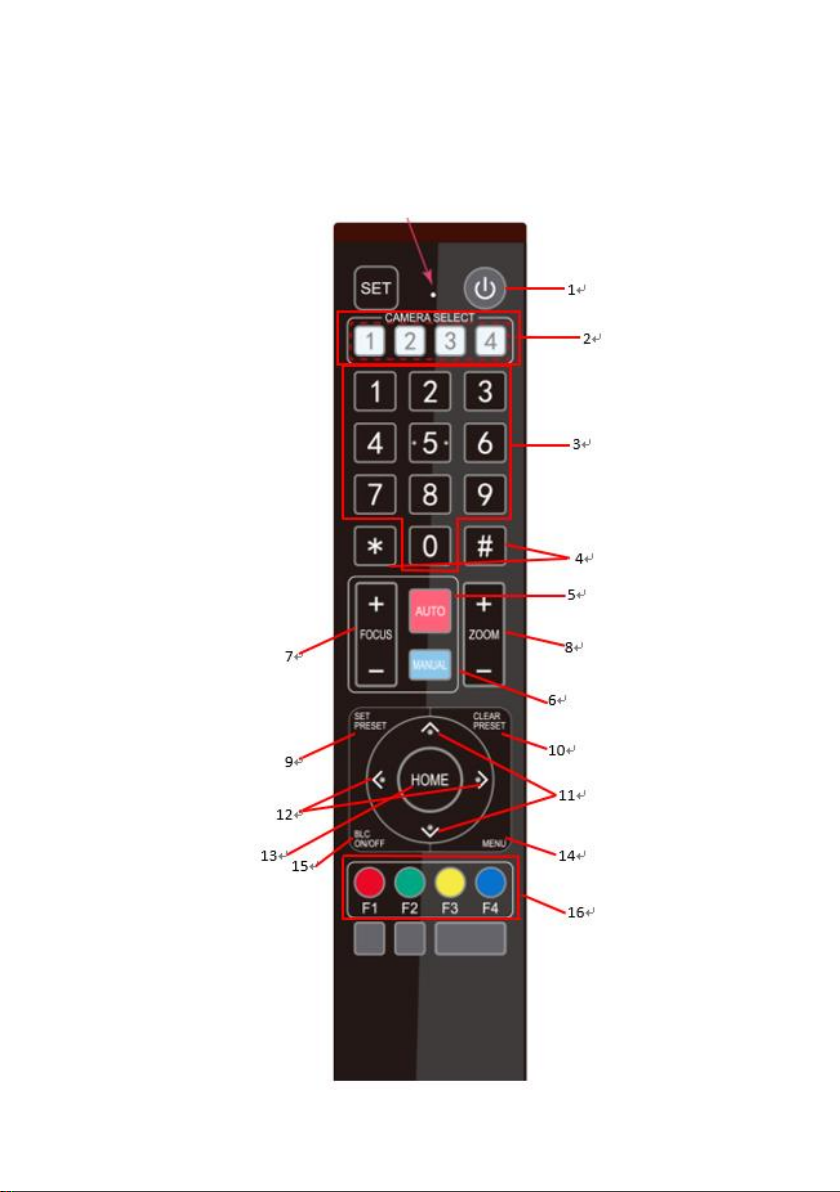
5.1 Remote Control Functions
20
Page 21
No
Function Keys
Descriptions
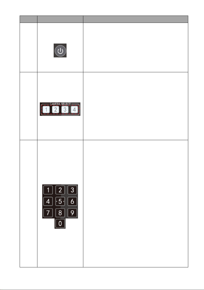
1
Standby Key
Standby Key
The standby button turns ON/OFF the camera.
To reboot the camera, press the standby button
for 3 seconds. After device initialization is
complete, the camera head will automatically
return to HOME position.
2
Camera Select Keys
Camera Select Keys
To select a camera in a multi-camera environment
using camera select keys (CAM1 – CAM4), you
should first assign an ID number to the camera
intended for operation using F1 – F4 keys then
press CAMERA SELECT (CAM 1~ CAM4) keys to
navigate between the four cameras.
Note: See F1 – F4 keys for ID number assignment
instructions.
3
Number Keypad
Number Keypad
Set, recall and clear presets using the number
keypad.
Set Preset
Please press the SET PRESET at first, and then
please press any of the number keys from 0 to 9
to save the PTZ settings. You will be allowed to
save up to up to 10 presets using the remote
control.
Call Preset
Press any of the number keys from 0 to 9 to recall
the preset settings.
Note: Make sure the preset that you want to
recall contains PTZ settings before pressing the
number key.
Clear Preset
First press the CLEAR/PRESET key then the
number key (0 – 9) to empty the preset.
21
Page 22
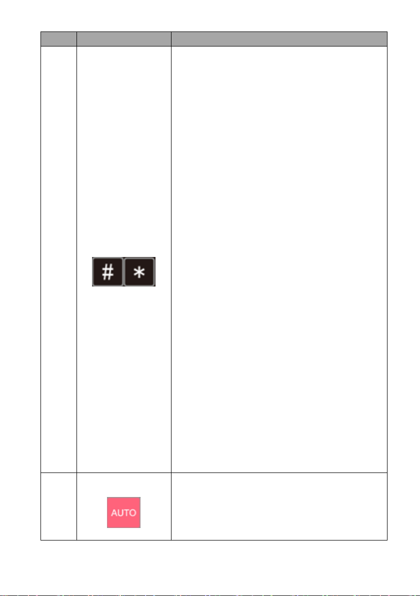
No
Function Keys
Descriptions
4
Asterisk and Pound
Keys
The asterisk and pound keys form various
combinations with other keys to access certain
functions directly.
The shortcuts are listed as follows:
1. 【#】+【#】+【#】: Clear all presets
2. 【*】+【#】+【6】: Restore factory defaults
3. 【*】+【#】+【9】: Image flip along
horizontal axis
4. 【*】+【#】+ AUTO: Enable auto focus
mode
5. 【*】+【#】+【3】: Set OSD MENU
language to Chinese.
6. 【*】+【#】+【4】: Set OSD MENU
language to English.
7. 【*】+【#】+ MANUAL: Restore default user
name, password, and IP address.
8. 【#】+【#】+【0】: Set video format to
1080P60.
9. 【#】+【#】+【1】: Set video format to
1080P50
10. 【#】+【#】+【2】: Set video format to
1080I60
11. 【#】+【#】+【3】: Set video format to
1080I50
12. 【#】+【#】+【4】: Set video format to
720P60
13. 【#】+【#】+【5】: Set video format to
720P50
14. 【#】+【#】+【6】: Set video format to
1080P30
15. 【#】+【#】+【7】: Set video format to
1080P25
5
AUTO Focus
AUTO Focus
Pressing this key will enable auto focus mode.
22
Page 23
No
Function Keys
Descriptions
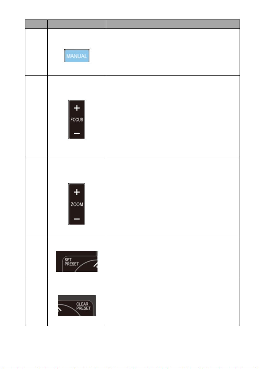
6
Manual Mode
Manual Focus
Pressing this key enables manual mode allowing
you to adjust the camera’s focus and zoom by
pressing Focus+/- and Zoom+/- keys.
7
Focus +/-
Focus
Press and hold Focus+ or Focus- to adjust the
focus accordingly and release as soon as the
desired focus is reached.
Note: Before adjusting the focus using Focus +/key, press the manual key to enable manual
mode.
8
Zoom In (+) / Zoom
Out (-)
Zoom
Press and hold Zoom + or Zoom- to zoom in and
out respectively and release as soon as the
desired zoom is reached.
Note: Before adjusting the zoom using Zoom +/key, press the manual key to enable manual
mode.
9
SET PRESET
SET PRESET
Press SET PRESET to set presets. See Number
Keypad description for instructions.
10
CLEAR PRESET
CLEAR PRESET
Press CLEAR PRESET to clear presets. See Number
Keypad description for instructions.
23
Page 24
No
Function Keys
Descriptions
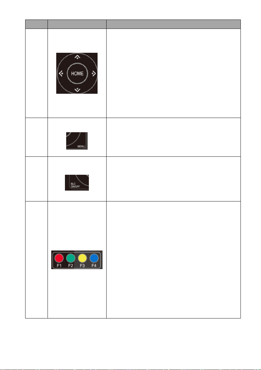
11-13
Direction Arrows
Direction Arrow Keys
Press the arrow keys to move the camera head
up, down, left and right.
Home Key
Press Home to return the camera head to the
center.
Note: In the OSD menu, press Home to enter the
selected option item and MENU to exit.
14
MENU
MENU
Open or close the camera’s OSD menu.
15
BLC ON/OFF
BLC ON/OFF
Press BLC ON/OFF to turn ON/OFF the backlight
compensation.
16
F1 – F4 Keys
F1 – F4 Keys
Assign an ID number to the camera intended for
operation using F1 – F4 keys by pressing the
combination keys as described below.
CAM1:【*】+【#】+【F1】
CAM2:【*】+【#】+【F2】
CAM3:【*】+【#】+【F3】
CAM4:【*】+【#】+【F4】
Use Camera Select keys to select the camera
intended for operation after you’ve assigned an ID
number to each camera.
Note: If users press the *+#+MANUAL buttons, the IP address of the PTC-140NDI
will be resumed to factory default 192.168.5.163
24
Page 25

5.2 On-Screen Menu
Main Options
Language
Setup
Camera
P/T/Z
Video
Format
Network
Settings
Version
Restore
Default
Sub
-Options
English
Protoc
ol
Exposu
re
Speed by
Zoom
1080P60
DHCP
MCU
Version
Restore
Default
Simplified
Chinese
VISCA
Addre
ss
Color
Zoom
Speed
1080P50
IP Addr
Camera
Version
VISCA
Addre
ss Fix
Image
Acc
Curve
1080I60
AF
Version
PELCO
-P
Addre
ss
Focus
Preset
Speed
1080I50
PELCO
-D
Addre
ss
Noise
Reducti
on
Joystic
Pan Dir
1080P30
Baudr
ate
Style
Joystic
Tilt Dir
1080P25
RS485/4
22
720P60
720P50
1080P59.
94
On-Screen MENU
Language
Setup
Camera
P/T/Z
Video Format
Network Settings
Version
Restore Default
Escape
[↑↓] Select [← →] Change Value
[Menu] Back [Home] OK
On-Screen Menu allows the user to modify various camera settings. Press [MENU]
on the remote control to open the on-screen menu as shown below.
The table below summarizes the main option items and their sub-options.
25
Page 26

Main Options
Language
Setup
Camera
P/T/Z
Video
Format
Network
Settings
Version
Restore
Default
1080I59.
94
1080P29.
97
720P59.9
4
Main Menu
Sub Menu
Options
Sub-options
Language
English
Simplified Chinese
Setup
Protocol
Auto
VISCA
PELCOO-D
PELCCO-P
VISCCA Address
1-7
VISCA Address Fix
ON/OFF
PELCO-P Address
1-255
PELCO-D Address
1-255
Baudrate
2400
4800
9600
38400
115200
RS-485/422
RS-485
RS-422
Camera
Exposure
Mode
Auto
Manual
SAE
AAE
Bright
EV
ON
OFF
EV Level
0
1
2
3
Details of all options in the on-screen menu are listed in the table below.
26
Page 27

Main Menu
Sub Menu
Options
Sub-options
4
5
6
7
-7
-6
-5
-4
-3
-2
-1
BLC
ON
OFF
Flicker
OFF
50Hz
60Hz
Gain Limit
0~15
DRC
Closed
1 2 3
4
5
6
7
8
Color
WB Mode
Auto
3000K
3500K
4000K
4500K
5000K
5500K
6000K
6500K
7000K
Manual
Onepush
RG Tuning
0
27
Page 28

Main Menu
Sub Menu
Options
Sub-options
1
2
3
4
5 6 7
8
9
10
-10
-9
-8
-7
-6
-5
-4
-3
-2
-1
BG Tuning
0
1
2
3
4
5
6
7 8 9
10
-10
-9
-8
-7
-6
-5
-4
-3
28
Page 29

Main Menu
Sub Menu
Options
Sub-options
-2
-1
Saturation
60%
70%
80%
90%
100%
110%
120%
130%
140%
150%
160%
170%
180%
190%
200%
Hue
0
1 2 3
4
5
6
7
8
9
10
11
12
13
14
AWB Sensitivity
High
Low
Middle
Image
Brightness
0
1
2
3
29
Page 30

Main Menu
Sub Menu
Options
Sub-options
4
5
6
7
8 9 10
11
12
13
14
Contrast
0
1
2 3 4
5
6
7 8 9
10
11
12
13
14
Sharpness
0
1 2 3
4
5
6
7
8 9 10
11
12
30
Page 31

Main Menu
Sub Menu
Options
Sub-options
13
14
15
Flip-H
ON
OFF
Flip-V
ON
OFF
B & W Mode
Color
Black & White
Gamma
Default
0.45
0.50
0.55
0.63
DCI
Closed
1
2
3
4 5 6
7
8
Focus
Focus Mode
Auto
Manual
Onepush
AF-Zone
Top
Center
Bottom
All
AF-Sensitivity
High
Low
Middle
Noise Reduction
NR-2D
Auto
OFF 1 2
3
4
31
Page 32

Main Menu
Sub Menu
Options
Sub-options
5
6
7
NR-3D
OFF
1 2 3
4
5
6
7
8
Dynamic Hot Pixel
OFF
1 2 3
4
5
Style
Default
Normal
Clarity
Bright
Soft
P/T/Z
Zoom by Speed
ON
OFF
Zoom Speed
1
2
3
4
5 6 7
8
Acc Curve
Standard
Slow
Fast
Preset Speed
Fast
Slow
Middle
32
Page 33

Main Menu
Sub Menu
Options
Sub-options
Joystick Pan Dir
Positive
Negative
Joystick Tilt Dir
Positive
Negative
Video Format
1080P60
1080P50
1080I60
1080I50
1080P30
1080P25
720P60
720P50
1080P59.94
1080I59.94
1080P29.97
720P59.94
Network Settings
DHCP
ON OFF
IP Addr
192.168.x.x
Version
MCU Version
Camera Version
AF version
Restore Default
Restore Default
(Yes/No)
Note:
Please remember to use the PTC-140NDI web UI and the OSD menu to
If the “Network Settings” option in the PTC-140NDI OSD menu is used for
modify the DHCP ON/OFF setting, and then the IP address information
which is shown in the OSD menu and the web UI will be consistent.
setting, users must reboot the PTC-140NDI after setting the “Network
Settings” option and then the setting will be effective.
33
Page 34

5.3 Professional Jargon Explanations of the OSD Menu
There are some professional jargons or nouns which are shown in the OSD menu
of the PTC-140NDI camera, please refer to this section for realizing those jargons.
Speed by Zoom: When this function is turned “ON”, at the time when the
zoom-in/zoom out is beginning or it is about to reach the zoom-in/zoomout limit or users want to stop zooming in/zooming out, the zoom-in/zoomout speed of the camera lens will be reduced linearly. When this function is
turned “OFF”, the zoom-in/zoom-out speed will be consistent no matter
when the camera zoom-in is started or stopped.
Joystick Pan Dir:Because the PTC-140NDI can use the upside down
installation, if this option is set as “Positive”, the PTZ camera lens moving
direction will be consistent to the direction which is selection by the remote
controller. If this option is set as “Negative”, the PTZ camera lens moving
direction will be reverse to the direction which is selected by the remote
controller.
Joystick Tilt Dir :Because the PTC-140NDI can use the upside down
installation, if this option is set as “Positive”, the PTZ camera lens moving
direction will be consistent to the direction which is selection by the remote
controller. If this option is set as “Negative”, the PTZ camera lens moving
direction will be reverse to the direction which is selected by the remote
controller.
Flip-H: This is the “Horizontal Flipping”. When “ON” is selected, the screen
which is shot by the camera will flip horizontally. If “OFF” is selected, the
screen will be shown in normal direction.
Flip-V: This is the “Vertical Flipping”. When “ON” is selected, the screen
which is shot by the camera will flip vertically. If “OFF” is selected, the
screen will be shown in normal direction.
34
Page 35

6. Installation Instructions
Ceiling Bracket (Upper
and Lower Plates
Upper Plate
Lower Plate
Note: Only mount the bracket on formwork or concrete surface. Do NOT mount
the bracket on plasterboard.
In your product package, you should find
PA4*30 self-tapping screw x 4
PA4 plastic screw stopper x 4
PM3*5 screw x 6
Ceiling bracket (upper and lower plates) x 1
PTC-140NDI camera x 1
Step 1: The Ceiling Bracket
Separate the ceiling bracket into two parts (upper and lower plates) as depicted
in the diagram below.
35
Page 36

Step 2: Mount the bracket’s upper plate to the ceiling
Upper Plate of Ceiling Bracket
Insert the four PA4 plastic screw stoppers into the ceiling as shown in the diagram
below.
Using four PA4*30 self-tapping screws, affix the bracket’s upper plate to the
ceiling.
Step 3: Affix the bracket’s lower plate to the bottom of PTC-140NDI
As depicted in the diagram below, use three PM3*5 screws to affix the bracket’s
lower plate to the bottom of PTC-140NDI.
36
Page 37

Step 4: Mount the PTC-140NDI Camera to the ceiling
Lower Plate of Ceiling Bracket
Now push the PTC-140NDI camera into the bracket’s upper plate in the direction
as indicated by the arrow in the diagram below. Make sure the two plates click
into place.
Finally, secure the PTC-140NDI camera to the upper plate with three PM3*5
screws.
37
Page 38

Step 5: Final
Push the PTC-140NDI
camera into the bracket’s
upper plate in the direction
as indicated by the arrow.
Make sure the two plates
click into place.
Lower Plate of Ceiling Bracket
Upper Plate of Ceiling Bracket
38
Page 39

7. Network Connection
Ethernet Cable
192.168.5.X
192.168.5.163
The Ethernet port on the back panel of your PTC-140NDI allows you to connect to
camera from the PC/Laptop with Static or dynamic IP addresses. To access and
modify these network settings, you will need to login to the camera’s web
interface.
If this is your first time using the device, please note that the camera’s default IP
address is 192.168.5.163.
Set up direct connection between the camera and your PC/laptop as depicted in
the diagram below; remember to manually assign an IP address of 192.168.5.X to
your PC/laptop.
On your PC/laptop, open a web browser and in the address bar, enter the
camera’s default IP address, 192.168.5.163 then press the ENTER key which
should take you to login page of the web interface.
39
Page 40

The default login credentials are:
User Name: admin
Password: admin
After you have successfully login to the web interface, click “Configuration”
“Ethernet” to open the network settings page on which you should be able to see
a list of options allowing you to set the camera’s connection mode to DHCP or
static IP.
In this chapter, we will show you how to enable DHCP and Static IP modes on
PTC-140NDI in two separate sections.
Note: To log out of the web interface, simply click “Logout” at the top right
corner of the page.
7.1 DHCP Mode
Dynamic Host Configuration Protocol (DHCP) is a network protocol that enables a
server to automatically assign an IP address to a network device from a defined
range of numbers configured for a given network. The diagram below illustrates a
DHCP network connection example.
40
Page 41

In order to enable the camera’s DHCP mode, simply check the DHCP checkbox to
allow the router to dynamically assign an IP address to PTC-140NDI.
Click “Save” button to save the new settings then reboot PTC-140NDI.
41
Page 42

7.2 Static IP
A static IP address is a fixed address manually assigned to PTC-140NDI. First
uncheck the DHCP checkbox then enter an IP address for the camera, the subnet
mask and the gateway IP.
Note: Never assign an address that ends in .0 or .255 as these addresses are
typically reserved for network protocols. An address to the very start of the IP
pool is also not recommended as it is always reserved for the router.
After you’ve configured the camera’s static IP, click “Save” button to save the
new settings then reboot PTC-140NDI.
7.3 DVIP
DVIP is a special network configuration software tool designed for DVIP device
search on the same network and configuring device network settings such as
Hostname, DHCP mode, IP address, subnet mask, gateway IP, and primary and
secondary DNS.
Depending on your operating system, download DVIP Configuration Tool from
the respective sites listed as follows:
PC: https://www.microsoft.com/en-us/p/dvip-network-
config/9p6gtz839k6s?activetab=pivot%3Aoverviewtab
Android:
https://play.google.com/store/apps/details?id=com.datavideo.dvipnetconfig&hl=
en_US
iOS: https://itunes.apple.com/tw/app/dvip-network-config/id1177895983?mt=8
After you’ve installed the DVIP Network Configuration Tool, follow the steps
outlined below to scan for online DVIP devices and configure their corresponding
settings.
42
Page 43

Step 1: Open the DVIP Network Configuration Tool and then select the connected
Ethernet option from the “Network interface” pop-up window. After that
please press the “OK” button.
Step 2: After the Network interface is selected, the DVIP Network Configuration
Tool interface will be shown as following diagram.
43
Page 44

Step 3: Please press “HOST NAME” and then the network settings pop-up window
will be shown.
44
Page 45

Step 4: users can click “Host Name” column for changing the device name. Users
can also click each setting column for changing value if it is needed. After that,
please press “Save” for saving those settings. Users can also press “Default” for
resuming those settings to factory default value.
45
Page 46

8. Web User Interface
The web based user interface allows you to set and control your PTC-140NDI
devices.
8.1 Preview
In preview, you will be able to see the camera image in real time as shown in the
diagram below. Click on the preview window once to view in full screen mode
and click again to exit.
At the bottom right corner of the camera image display window, click
the “Stream” button to switch between Main Stream and Sub Stream
previews. See Video Encode in Configuration tab for stream settings.
Click this “Audio” button once to turn on the sound, and then click
this button again to turn off the sound.
Click this “Full” button to enlarge the screen size to Full Screen.
Note: The Preview window can support the image preview for the image which is
compressed in H.264 format and the Profile is set in BP or MP. If the Profile of the
image is HP or the image is compressed in H.265 format, this image can not be
shown in the Preview window.
46
Page 47

If the H.264 format is selected, the preview screen can be shown normally
which is shown as following diagram.
If the H.265 format is selected, there is no screen in the Preview window
and there is a warning message that will be shown.
Control Functions Further to the right, there are various control functions, such as PTZ control, PTZ
speed slider, focus mode drop-down menu, zoom and focus controls, as well as
presets for saving PTZ settings. Details of each will be described in the table
below.
47
Page 48

Controls
Descriptions
PTZ Control Buttons
Click the arrow buttons to move the
camera head to corresponding
directions.
To return to Home position, click .
PTZ Speed Slider
The PTZ speed slider adjusts the P/T
speed, ranging from 0 (slowest) to 100
(fastest). The default speed is 50.
Slide right to increase the speed and
left to decrease.
Focus Mode
Select focus mode from the drop-down
menu; available options are Auto,
Manual and One Push.
Auto: Automatic focus
Manual: Manual focus
One Push: One time automatic focus.
Focus Far/Near
Click (FAR) and (Near)
buttons accordingly to manually focus
the camera lens onto the subject.
Note: You will not be able to manually
adjust the camera focus if focus mode
is set to Auto or One Push.
Zoom IN/OUT
Click to zoom in and to zoom
out.
48
Page 49

Preset
Functions
Descriptions
Preset Drop-Down Menu
Select a preset number from the dropdown menu.
Note: There are 255 presets ranging
from 0 – 254.
Set Button
Click Set button to save PTZ settings to
the selected preset number.
Delete Button
Click Clear button to remove PTZ
settings from the selected preset
number.
Run Button
Click Run button to recall PTZ settings
from the selected preset number.
The presets allow you to save multiple PTZ settings to the camera. See function
descriptions in the table below.
Set the Preset
To set the preset, follow the steps outlined below.
1. First adjust the camera head to the desired pan and tilt positions.
2. Make sure zoom and focus are adjusted as well.
3. Select a preset number from the Preset drop-down menu.
4. Click the Set button to save the PTZ settings to the selected preset
Recall the Preset
To recall a saved preset, simply select a preset number from the Preset dropdown menu then click the Run button to apply the saved settings.
number.
49
Page 50

8.2 Configuration
Items
Descriptions
Enable
Check this checkbox to enable audio
settings.
Input Type
This allows users to select the audio
input type. It provides Line IN for the
audio input type.
In Configuration, you will be able to configure the camera’s audio, video, network
and system settings which will be described further in the next few sections.
Audio Configure
Audio Configure allows you to configure the input audio source.
See the table below for descriptions of each item.
50
Page 51

Items
Descriptions
Encode Type
Select an encode type for your input
audio source. The available encode
types include MP3, AAC and G.711A.
Sample Rate
Select a sample rate for your input
audio source. The higher the sample
rate, the better the audio quality.
Sample Bits
Select the sample bits for your input
audio source. The default is 16.
Bit Rate
Select a bit rate for your input audio
source. Available bit rates are:
32 Kbps
48 Kbps
64 Kbps
96 Kbps
128 Kbps
Channel
Set your input audio source to Mono.
Volume Slider
Adjust the volume of your input audio
source using the volume slider (Min: 1
/ Max: 10).
51
Page 52

Items
Descriptions
Save Button
Click the Save button to save the new
audio settings.
Video Configure
Items
Descriptions
Compressed Format
Select either H.264 or H.265 video
compression.
Video Configure allows you to configure the input video source.
Video Encode
In Video Encode, you will be able to configure the video quality for main and sub
streams. See the diagram below for various video settings.
See the table below for descriptions of each item.
52
Page 53

Profile
Select a profile for your input video
source. Available profiles are:
BP: Baseline Profile (Default)
MP: Main Profile
HP: High Profile.
Image Size
Select an appropriate image size from
the drop-down menu.
1920 x 1080
1280 x 720
640 x 480
Rate Control
CBR encoding does not optimize media
files for quality but will save you
storage space. VBR takes longer to
encode but produces the most
favorable results as the quality of the
media file is superior.
Image Quality
The default image quality for the main
stream is “Best.”
The default image quality for the sub
stream is “Better.”
53
Page 54

Bit Rate
A bitrate is the amount of data
required to encode a single second of
video. From a streaming perspective,
the higher the bitrate, the higher the
quality, and the more bandwidth it will
require.
The default bit rate for the main
stream is “4096 Kb/s.”
The default bit rate for the sub stream
is “512 Kb/s.”
Frame Rate
Higher frame rate will result in smooth
video viewing experience. The frame
rate is 25 by default.
I Frame Interval
A shorter I Frame Interval results
higher quality video but consumes
more network bandwidth. On the
other hand if longer I Frame Interval is
set, less bandwidth will be required but
it will result in lower video quality. I
frame interval is 75 by default.
I Frame Min QP
A low QP value means less
compression but higher video quality.
The default value is 20.
Stream Name
Enter a stream name for the main and
sub stream.
Save Button
Click the Save button to save the new
video settings.
54
Page 55

Stream Publish
Items
Descriptions
Enable
Check this checkbox to enable
RTMP stream.
Protocol Type
There are three streaming
protocols including RTSP, RTMP
and SRT for users to select.
Host Address
This is the RTMP Server URL/RTSP
Server URL provided by the video
streaming providers. An example of
the RTMP Server URL is provided.
In Stream Publish, you will be able to configure the RTSP, RTMP or SRT settings
for main and sub streams.
See the table below for descriptions of each item.
55
Page 56

Items
Descriptions
Host Port
The host port number is 1935 by
default.
Stream Name
This is the RTMP/RTSP Stream
Name/Key provided by the video
streaming providers. An example of
the RTMP Stream Name/Key is
provided.
User Name / Password
Enter the login credentials of your
live streaming platform or the
Source Username & Source
Password which are provided by
the RTSP streaming platform.
Password for stream encryption
If users select the SRT stream and
want to set a password for the SRT
stream, this column allows users to
enter their desired SRT stream
password.
Crypto key length in bytes
If users select the SRT stream, the
“Crypto Key length in bytes” allows
users to select their desired SRT
crypto key length. There are 4
different key lengths including
0/16/24/32 for users to select.
Note: The unit of the crypto key
length is bytes. If 0 is selected, it
means that there is no crypto key
for this SRT stream.
56
Page 57

Items
Descriptions
Save Button
Click the Save button to save the
new RTMP settings.
Note:
1. The SRT Caller mode and the RTSP Publish can be operated only as the “Main
Stream”.
2. When the SRT Caller or the RTSP Publish is operated as the “Main Stream”, the
“Sub Stream” can not be operated at the same time.
Stream to Youtube
In this section, we will show you how to set up an RTMP(S) stream to Youtube.
The step-by-step setup is outlined as follows:
1. First of all, you have to obtain Server URL and Stream Name/Key from
Youtube.
2. Open the Youtube Live Dashboard
https://www.youtube.com/live_dashboard
3. On the left column, locate and click “Stream now.”
57
Page 58

4. On the right, scroll down to the bottom where you will be able to find Server
URL and Stream name/key.
5. Open the PTC-140NDI’s web UI and click “Video Configure” “Stream
Publish.”
6. Enter the Server URL and Stream Name/Key into Host Address and Stream
Name respectively.
7. Check the Enable checkbox to enable RTMP stream.
8. Click the Save button to save the RTMP settings and start broadcasting your
camera video on Youtube.
58
Page 59

Stream to Facebook
Use Facebook Live Producer for Streaming
1. Go to Facebook Live website
https://www.facebook.com/formedia/solutions/facebook-live, and then
click “Live Producer” or “facebook.com/live/producer” links from “How to go
live on Facebook with a camera and streaming software” section.
Note: Facebook Live limits each stream to 8 hours.
2. Check “Use stream key” then copy and paste “Server URL” and Stream Key”
into “Host Address” and “Stream Name” as shown on the PTC-140NDI’s web
UI respectively. Please modify the “Host Port” to 443.
59
Page 60

3. Check the Enable checkbox to enable RTMP stream.
4. Click the Save button to save the RTMP settings.
5. Please press the “Reboot” button from the Reboot option from the
PTC-140NDI Web UI.
6. The preview screen will be shown on the bottom-right corner of the
Facebook Live page. Please select where you want to post your livestreaming and who can see your live-straming. After that, please enter the
title of the live-streaming and then please click “Go Live” button for livestreaming the video which is shot by the camera to the Facebook page.
60
Page 61

7. After the live-streaming is started, users can see related information for the
live-streaming video from the Facebook Live interface. If you want to stop the
live-streaming, please click the “End Live Video” button for stopping your
Facebook live-streaming.
61
Page 62

Use your personal Facebook Page or Facebook Fan Page for Live-
Streaming
1. Please press “Live Video” button from your personal Facebook Page or the
Facebook Fan Page.
2. Check “Use stream key” then copy and paste “Server URL” and Stream Key”
into “Host Address” and “Stream Name” as shown on the PTC-140NDI’s web UI
respectively. Please modify the “Host Port” to 443.
3. Check the Enable checkbox to enable RTMP stream.
4. Click the Save button to save the RTMP settings.
5. Please press the “Reboot” button from the Reboot option from the PTC140NDI Web UI.
6. The preview screen will be shown on the bottom-right corner of the Facebook
Live page. Please select where you want to post your live-streaming and who can
see your live-straming. After that, please enter the title of the live-streaming and
then please click “Go Live” button for live-streaming the video which is shot by
the camera to the Facebook page.
62
Page 63

7. After the live-streaming is started, users can see related information for the
live-streaming video from the Facebook Live interface. If you want to stop
the live-streaming, please click the “End Live Video” button for stopping your
Facebook live-streaming.
63
Page 64

How to Stream the RTSP Streaming to Wowza Cloud Streaming Platform
Wowza Streaming Cloud is a cloud streaming platform which is a global leader in
the live-streaming area. This chapter will take Wowza Streaming Cloud as an
example to show how to do the RTSP streaming by Datavideo PTC-140NDI with
the Wowza Streaming Cloud. Please see following steps to know how to stream
the RTSP streaming by the PTC-140NDI camera to Wowza Streaming Cloud.
1. Please go to Wowza official website www.wowza.com which is shown as
following diagram.
2. Please click “MY ACCOUNT” option for entering your Wowza Account and
Password.
64
Page 65

3. If you already have your own Wowza account, please enter your Email Address
and Password and then click the “Sign In” button for logging into your own
Wowza account which is shown as following diagram. If you do not have the
Wowza account, you can apply a Wowza trial account for a 30 day free trial.
4. Because this example takes Wowza trial account as an example, so, after
logging into your account, please click the “FREE TRIAL” button which is located
on the top-right corner.
65
Page 66

5. After logging into your account, users can see that there are two kinds of
products including “Wowza Streaming Cloud” and “Wowza Streaming Engine”.
What we need is the Wowza Streaming Cloud, so, please click the “FREE TRIAL”
button of the “Wowza Streaming Cloud”.
66
Page 67

6. Please click the “Launch Wowza Streaming Cloud” button for launching the
Wowza Streaming Cloud.
7. You will see the main interface of the Wowza Streaming Cloud which is shown
as following diagram. Please click “Add Live Stream” button for adding a new livestreaming.
67
Page 68

8. Please enter your desired name for the stream into the “What is the name of
your live stream?” column. For this example, the stream name is “RTSP Stream”.
9. Please click one of the following countries which is located at the nearest
location to where you want to start the live-streaming. Moreover, please click the
“Next” button. In this example, please select “Asia Pacific Taiwan”.
68
Page 69

10. Please select the camera or the encoder that you want to use to connect to
Wowza Streaming Cloud. This example is RTSP streaming, so, please select “Other
RTSP” option from the following diagram. You can keep other options as default
values. After that, please click the “Next” button.
69
Page 70

11. This page allows users to set some detailed settings. After all parameters are
set, please click the “Next” button.
70
Page 71

12. Please enter your desired title and then click the “Next” button.
13. This page allows you to check all parameters before starting the livestreaming. Please confirm that all parameters are correct and then click the
“Finish” button.
14. Please do the streaming settings according to following steps.
Please click the “Start Stream” button, after those reminder is shown,
please click the “Start” button.
71
Page 72

Moreover, please copy the “Primary Server” address and paste it into the
“Host Address” column in the “Stream Publish” option of the PTC-140NDI
Web UI.
Please copy the “Host Port” and then paste it into the “Host Port” column
in the “Stream Publish” page of the PTC-140NDI Web UI. Please copy the
“Stream Name” and then paste it into the “Stream Name” column in the
“Stream Publish” page of the PTC-140NDI Web UI.
Please copy the “Source Username” and then paste it into the “Username”
column in the “Stream Publish” page pf the PTC-140NDI Web UI.
Please copy the “Source Password” and then paste it into the “Password”
column in the “Stream Publish” page of the PTC-140NDI Web UI.
72
Page 73

15. After those data are pasted, please click the “Save” button.
16. Please click the “Reboot” button from the “Reboot” option in the PTC-140NDI
Web UI.
17. Users can see the image which is shot by the PTC-140NDI is streamed to
Wowza Streaming Cloud platform successfully by using the RTSP protocol.
73
Page 74

How to do the SRT Streaming by the vMix Software
How to install the Vmix Software
Please install the vMix software according to following steps.
1. At first, please go to vMix official website and then download the vMix 60-day
free-trial. This section will use vMix free-trial as an example to demonstrate the
operation steps. Please click the “DOWNLOAD FREE TRIAL” button for
downloading.
2. Please double-click the vmix23.exe .
3. Please click the “Next” button.
74
Page 75

4. Please click “I accept the agreement” and then click the “Next” button.
5. Please click the “Next” button.
75
Page 76

6. Please click the “Next” button.
7. Please click the “Next” button.
76
Page 77

8. Please click the “Install” button.
9. The installation will be started.
77
Page 78

10. Please click the “Finish” button to finish the installation.
11. Please select “Register for a fully functional 60 Day Trial” to fill out your Email
Address. After that, please click the “OK” button to open the vMix software.
78
Page 79

12. Please select the initial resolution and frame rate that you want to use and
then please click the “OK” button.
13. After opening vMix, the software interface is shown as following diagram.
79
Page 80

How to do the SRT Stream by Using the PTC-140NDI Camera and vMix Software
There are two modes for the SRT streaming including the Caller Mode and the
Listener Mode. Please see following steps for realizing operation steps for the
vMix.
If the PTC-140NDI is set in Listener Mode
Note: If vMix is set in Caller Mode, the PTC-140NDI Web UI must be set in
Listener Mode. If vMix is set in Listener Mode, the PTC-140NDI Web UI must be
set in Caller Mode.
1. At first, please click “vMix(x64)” from the Start Menu.
80
Page 81

2. Users can see the main interface of the vMix which is shown as following
diagram.
3. Please go back to the interface of the PTC-140NDI Web UI, click the “SRT”
option, and then select your desired SRT encryption way from “Crypto key length
in bytes”. For this example, “32” is selected. After that, please set your desired
SRT password in “Password for stream encryption”. For this example, it is
“8888888888”. The default SRT port is “9000” and it is no need to change this
value. After all settings are finished, please click the “SAVE” button.
81
Page 82

4. Please click the “Reboot” button from the “Reboot” option for rebooting the
PTC-140NDI.
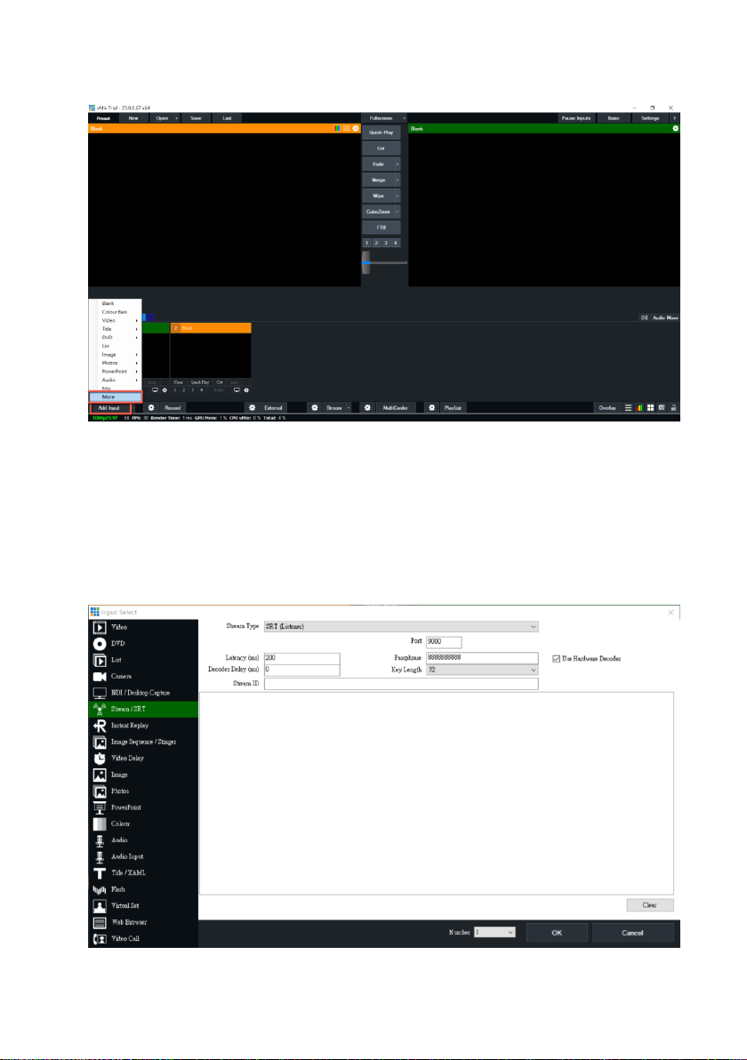
5. Please go back to vMix and then please click “Add Input”. After that, please
click “More” from the drop-up menu.
82
Page 83

6. At this time, please click the “Stream/SRT” option from the “Select Input”
interface. Select “SRT Caller” from the “Stream Type” drop-down menu. After
that, please enter the IP address of your connected device. In this example, it is
the PTC-140NDI and its IP address is 192.168.2.5. After that, please enter the
password that is set in the PTC-140NDI Web UI, which is “8888888888” in the
“Passphrase” column. And then please select “32” in the “Key length” drop-down
menu to make sure that it is consistent as the setting in the PTC-140NDI Web UI.
7. Please click the “OK” button.
83
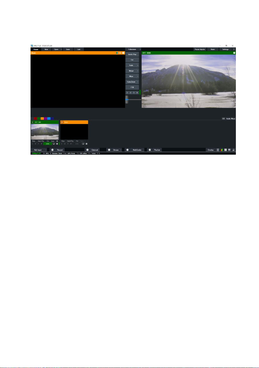
Page 84

8. Users can see that the image which is shot by the PTC-140NDI is streamed to
vMix software by the SRT Listener Mode.
84
Page 85

If the PTC-140NDI is set in Caller Mode
Note: If vMix is set in Caller Mode, the PTC-140NDI Web UI must be set in
Listener Mode. If vMix is set in Listener Mode, the PTC-140NDI Web UI must be
set in Caller Mode.
1. At first, please click “vMix(x64)” from the Start Menu.
2. Users can see the main interface of the vMix which is shown as following
diagram.
85
Page 86

3. Please go back to the interface of the PTC-140NDI Web UI, click the “Stream
Publish” option, and then you can see the “Stream Publish” interface which is
shown as following diagram.
4. Please select “SRT” option from the “Protocol Type” drop-down menu.
5. Please enter the IP address of the device that the vMix software is installed in
the “Host Address” column. In this example, it means the Notebook PC, and its IP
address is 192.168.2.50.
6. The “Host Port” default value for the PTC-140NDI is 5000.
7. Please select 32 from the “Crypto key length in bytes” drop-down menu.
8. Please enter your desired SRT password in the “Password for stream
encryption” column. In this example, it is “8888888888”.
9. Please click the “SAVE” button .
10. Please click the “Reboot” button from the “Reboot” option for rebooting the
PTC-140NDI.
86
Page 87
11. Please go back to vMix and then please click “Add Input”. After that, please
click “More” from the drop-up menu.
12. Please select “SRT Listener” from the “Stream Type” drop-down menu. And
then please paste the “Host Port” default value “5000” in the “Stream Publish”
option into the “Port” column of the vMix software. After that, please set the
“Passphrase” password to “88888888” which is consistent to the “Password for
Stream Encryption” in the “Stream Publish” page of the PTC-140NDI web UI. After
that, please set the “Key length” drop-down menu to 32, which is consistent to
the PTC-140NDI web UI.
87
Page 88
13. Finally, please click the “OK” button.
14. Users can see that the image which is shot by the PTC-140NDI is streamed to
vMix software by the SRT Caller Mode.
88
Page 89

RTP Multicast
The RTP Multicast allows you to view camera video on certain video players such
as VLC media player from a remote location.
Follow the steps outlined below to view the camera video on VLC media player.
1. Download VLC media player from the link https://www.videolan.org.
2. Open VLC, click “Media” “Open Network Stream” then enter
rtp://224.1.2.3:4000 to view the main stream and rtp://224.1.2.3:4002 to
view the sub stream.
89
Page 90

3. Click the “Play” button to start viewing the video stream.
You can also choose to stream over TS protocol. Follow the steps outlined below
to view the camera video on VLC media player over TS protocol.
1. On RTP Multicast page of the PTC-140NDI’s web interface, select “TS” from
the Protocol Type drop-down menu.
2. Open VLC media player, click “Media” “Open Network Stream” then enter
udp://@224.1.2.3:4000 to view the main stream and udp://@224.1.2.3:4002
to view the sub stream.
90
Page 91

3. Click the “Play” button to start viewing the video stream.
Video Parameters
This sets the camera focus, exposure, color balance, image settings, noise
reduction and picture styles.
Focus
In Focus, you are allowed to set Focus Mode, Auto Focus Zone and Auto Focus
Sensitivity.
Focus Mode: Available modes are Auto, Manual and One Push.
AF-Zone: This sets auto focus zone by selecting Top, Center, Bottom or All
from the drop-down menu.
AF-Sensitivity: This sets auto focus sensitivity by selecting High, Middle and
Low from the drop-down menu.
91
Page 92

Exposure
In Exposure, you are allowed to set Exposure Mode, Exposure Value (EV),
Backlight Compensation (BLC), Anti-Flicker, Gain Limit and Dynamic Range
Compression (DRC).
Mode: Available focus modes are Auto, Manual, SAE (Shutter Automatic
Exposure), AAE (Aperture Automatic Exposure) and Bright.
Auto – Fully automatic settings for shutter speed and aperture with ability to
adjust gain, dynamic range, backlight and anti-flicker.
Manual – Full iris, shutter speed and range control
Shutter Automatic Exposure – The camera will measure light and
automatically set the aperture based on your desired shutter speed.
92
Page 93

Aperture Automatic Exposure – The camera will measure light and
automatically set the shutter speed based on your desired iris opening
(aperture).
EV: EV is exposure value. By turning it ON, an EV slider will appear for
adjusting the exposure value.
BLC: By turning the backlight compensation, the camera will compensate for
backlight by enhancing automatic exposure control on the camera.
Flicker: To avoid video flicker, you can set your camera flicker frequency to
50Hz or 60Hz.
Gain Limit Slider: Select gain limit from 0 to 15.
DRC: Sets the amount of Dynamic Range Compression where higher values
lead to more compression (1 – 8 or off).
Color
In Color, you are allowed to set color balance such as white balance, red gain fine
tuning, blue gain fine tuning, saturation, hue and automatic white balance
sensitivity. The color balance of your image will change the colors rendered in
your image.
93
Page 94

WB Mode: Select white balance mode from the options listed below.
- Auto
- Manual
- One Push
- VAR
o 2400K
o 2500K
o 2600K
o 2700K
o 2800K
o 2900K
o 3000K
o 3100K
94
Page 95

o 3200K
o 3300K
o 3400K
o 3500K
o 3600K
o 3700K
o 3800K
o 3900K
o 4000K
o 4100K
o 4200K
o 4300K
o 4400K
o 4500K
o 4600K
o 4700K
o 4800K
o 4900K
o 5000K
o 5100K
o 5200K
o 5300K
o 5400K
o 5500K
o 5600K
o 5700K
o 5800K
o 5900K
o 6000K
o 6100K
o 6200K
o 6300K
o 6400K
o 6500K
o 6600K
o 6700K
o 6800K
95
Page 96

o 6900K
o 7000K
o 7100K
RG Tuning: This fine tunes the red gain from -10 to 10 but effective only in
AUTO mode.
BG Tuning: This fine tunes the blue gain from -10 to 10 but effective only in
AUTO mode.
Saturation: 60% to 200%.
Note: The higher the saturation, the more vivid the colors will be.
Hue: Chroma adjustment from 0 to 14.
AWB Sensitivity: This is the white balance sensitivity; select Low, Middle or
High.
Image
Other image settings include brightness, contrast, sharpness, gamma, digital
cinema, black and white, orientation, digital zoom and ultra-low illumination.
96
Page 97

Bright: Brightness level adjustment from 0 to 14.
Contrast: Contrast adjustment from 0 to 14.
Sharpness: Sharpness adjustment from 0 to 15.
Gamma: Selects a gamma value from the following
- Default
- 0.45
- 0.50
- 0.55
- 0.63
97
Page 98

DCI: To enable DCI, simply select a value from 1 to 8; selecting OFF will
disable DCI.
B&W Mode: This allows you to switch between color and black-and-white
modes.
Flip-H: Turning it ON flips the image along the horizontal axis.
Flip-V: Turning in ON flips the image along the vertical axis.
DZoom: This enables/disables digital zoom.
Low-Light Mode: This enables/disables Low-Light Mode.
NR
Image noise is extremely distracting to viewers and enabling noise reduction will
remove noise to achieve a broadcast quality image.
98
Page 99

NR-2D: 2D noise reduction is ideal for scenes with movement.
- OFF
- 1 – 7
- Auto
NR-3D: 3D noise reduction is ideal for static fields of view.
- OFF
- 1 – 7
Note: By using both 2D and 3D noise reduction together, you can effectively
enhance both moving and static imagery, which is ideal for most live broadcast
environments.
Dynamic Hot Pixel: Hot pixels are bright colored spots in your images, often
noticeable with slow shutter speeds or high ISO settings. By enabling the
dynamic hot pixel feature, these spots will be automatically removed.
- OFF
- 1 – 5
Style
In Style, you will be able to select the picture style of your preference. The
available styles are:
Default
Normal
Clarity
Bright
Soft
99
Page 100

Note: Each time after you modify the camera parameters,
please click the Refresh button to apply the new settings.
Video OSD
In Video OSD, you will be allowed to show video time and title on the screen. You
can further set the font color as well as their positions.
100
 Loading...