

Page 1

HD/SD 12-CHANNEL
PORTABLE VIDEO STUDIO
HS-2850
( 8 / 12 CHANNEL )
Instruction manual
Page 2

Table of Contents
WARNINGS AND PRECAUTIONS ........................................................................................... 5
WARRANTY........................................................................................................................... 6
STANDARD WARRANTY ............................................................................................................ 6
THREE YEAR WARRANTY .......................................................................................................... 6
DISPOSAL .............................................................................................................................. 7
CHAPTER 1 INTRODUCTION ............................................................................................... 8
1.1 FEATURES .................................................................................................................. 8
1.2 SYSTEM DIAGRAM ...................................................................................................... 10
CHAPTER 2 CONNECTIONS AND CONTROLS..................................................................... 11
2.1 MAIN UNIT – REAR PANEL OVERVIEW ............................................................................ 11
2.1.1 Rear Panel Connections ..................................................................................... 11
2.2 CONTROL PANEL OVERVIEW ......................................................................................... 15
2.2.1 Video Switching ................................................................................................. 15
Program and Preset rows ......................................................................................... 15
Background .............................................................................................................. 16
2.2.2 Video Transitions ............................................................................................... 16
Transition Selection .................................................................................................. 16
Triggering the Transition........................................................................................... 17
2.2.3 Logo and Clock .................................................................................................. 18
2.2.4 Picture-in-Picture and Downstream Key ............................................................. 19
2.2.5 Frame Store and Audio Control .......................................................................... 20
2.2.6 Crosspoint ......................................................................................................... 20
2.2.7 OSD MENU Options ........................................................................................... 21
2.2.8 PC Control – SE Remote Control Software .......................................................... 26
SET Function ............................................................................................................. 26
REC & PLAY Functions ............................................................................................... 27
Software-based Macro Functions ............................................................................. 28
TIME Function .......................................................................................................... 28
2.3 INTERCOM & MONITOR CONTROL PANEL ........................................................................ 28
2.3.1 Intercom Function.............................................................................................. 28
2.3.2 Monitor Function ............................................................................................... 29
2.3.3 Monitor Menu Options ...................................................................................... 30
MAIN ADJUST ........................................................................................................... 31
COLOR ...................................................................................................................... 32
Information .............................................................................................................. 32
Special Function ....................................................................................................... 32
Factory Reset ............................................................................................................ 33
CHAPTER 3 SWITCHER CONFIGURATION UTILITY (SECONFIG SOFTWARE) ...................... 34
2
Page 3

3.1 NETWORK SETUP ....................................................................................................... 34
3.2 CONNECTING THE SECONFIG SOFTWARE TO THE SWITCHER ...................................................... 37
3.2.1 Change the Switcher IP Address ......................................................................... 38
3.3 SWITCHER TAB .......................................................................................................... 39
3.3.1 Profiles .............................................................................................................. 40
3.4 SETTINGS TAB............................................................................................................ 40
3.4.1 Inputs tab .......................................................................................................... 40
3.4.2 Audio Tab .......................................................................................................... 41
3.4.3 Video XPT Tab.................................................................................................... 44
3.4.4 Common Setup .................................................................................................. 46
3.4.5 Outputs Tab ....................................................................................................... 49
3.5 IMAGES UPLOAD TAB .................................................................................................. 50
3.5.1 Still Pictures ....................................................................................................... 50
3.5.2 Logos ................................................................................................................. 51
3.5.3 Dynamic Logo .................................................................................................... 52
3.6 MULTI SCREEN WINDOW SIGNS (LABELS) TAB .................................................................... 53
3.7 MULTIVIEW LAYOUT TAB ............................................................................................. 54
3.8 MULTIVIEW UPLOAD TABS (A / B / C) ............................................................................ 55
CHAPTER 4 SWITCHER VIDEO........................................................................................... 56
4.1 HDMI MULTI-VIEW ................................................................................................... 56
4.2 VIDEO LAYERS ........................................................................................................... 57
CHAPTER 5 AUDIO FUNCTION .......................................................................................... 59
5.1 OVERVIEW ............................................................................................................... 59
5.2 AUDIO MENU OPTIONS – DE-EMBEDDING SDI OR HDMI AUDIO .......................................... 59
5.3 AUDIO MENU OPTIONS – MONITORING THE AUDIO LEVELS .................................................. 61
5.4 AUDIO MENU OPTIONS – CHANGING THE AUDIO INPUT LEVEL .............................................. 62
5.5 WORKING WITH A FIXED OR SINGLE AUDIO SOURCE............................................................. 62
5.6 SWITCHING BETWEEN DIFFERENT EMBEDDED AUDIO SOURCES ............................................... 62
5.7 AUDIO DELAY ........................................................................................................... 63
CHAPTER 6 APPLICATIONS ............................................................................................... 64
6.1 PICTURE-IN-PICTURE FUNCTION .................................................................................... 64
6.2 DOWN STREAM KEYER ................................................................................................ 65
6.3 HS-2850 AND CG SETUP ............................................................................................ 65
CHAPTER 7 APPENDICES .................................................................................................. 69
APPENDIX 1 UPGRADING HS-2850 TO 12 CHANNELS ................................................................. 69
APPENDIX 2 TALLY OUTPUTS.................................................................................................. 71
APPENDIX 3 GPI / GPO CONNECTIONS .................................................................................... 73
APPENDIX 4 RS-422 PHYSICAL CONNECTION............................................................................. 74
APPENDIX 5 FIRMWARE UPDATE............................................................................................. 75
Keyboard Firmware Update ......................................................................................... 75
3
Page 4

T-Bar Re-Calibration ..................................................................................................... 78
Monitor Firmware Update............................................................................................ 79
APPENDIX 6 FREQUENTLY-ASKED QUESTIONS ............................................................................ 80
APPENDIX 7 DIMENSIONS & WEIGHT ....................................................................................... 81
APPENDIX 8 SPECIFICATIONS .................................................................................................. 82
SERVICE AND SUPPORT ...................................................................................................... 84
Disclaimer of Product & Services
The information offered in this instruction manual is intended as a guide only. At all times,
Datavideo Technologies will try to give correct, complete and suitable information. However,
Datavideo Technologies cannot exclude that some information in this manual, from time to
time, may not be correct or may be incomplete. This manual may contain typing errors,
omissions or incorrect information. Datavideo Technologies always recommend that you
double check the information in this document for accuracy before making any purchase
decision or using the product. Datavideo Technologies is not responsible for any omissions
or errors, or for any subsequent loss or damage caused by using the information contained
within this manual. Further advice on the content of this manual or on the product can be
obtained by contacting your local Datavideo Office or dealer.
4
Page 5

FCC Compliance Statement
This device complies with part 15 of the FCC rules. Operation is subject to the following two
conditions:
(1) This device may not cause harmful interference, and
(2) This device must accept any interference received, including interference that may cause
undesired operation.
Warnings and Precautions
1. Read all of these warnings and save them for later reference.
2. Follow all warnings and instructions marked on this unit.
3. Unplug this unit from the wall outlet before cleaning. Do not use liquid or aerosol
cleaners. Use a damp cloth for cleaning.
4. Do not use this unit in or near water.
5. Do not place this unit on an unstable cart, stand, or table. The unit may fall, causing
serious damage.
6. Slots and openings on the cabinet top, back, and bottom are provided for ventilation. To
ensure safe and reliable operation of this unit, and to protect it from overheating, do not
block or cover these openings. Do not place this unit on a bed, sofa, rug, or similar
surface, as the ventilation openings on the bottom of the cabinet will be blocked. This
unit should never be placed near or over a heat register or radiator. This unit should not
be placed in a built-in installation unless proper ventilation is provided.
7. This product should only be operated from the type of power source indicated on the
marking label of the AC adapter. If you are not sure of the type of power available,
consult your Datavideo dealer or your local power company.
8. Do not allow anything to rest on the power cord. Do not locate this unit where the
power cord will be walked on, rolled over, or otherwise stressed.
9. If an extension cord must be used with this unit, make sure that the total of the ampere
ratings on the products plugged into the extension cord do not exceed the extension
cord rating.
10. Make sure that the total amperes of all the units that are plugged into a single wall
outlet do not exceed 15 amperes.
11. Never push objects of any kind into this unit through the cabinet ventilation slots, as
they may touch dangerous voltage points or short out parts that could result in risk of
fire or electric shock. Never spill liquid of any kind onto or into this unit.
12. Except as specifically explained elsewhere in this manual, do not attempt to service this
product yourself. Opening or removing covers that are marked “Do Not Remove” may
expose you to dangerous voltage points or other risks, and will void your warranty. Refer
all service issues to qualified service personnel.
13. Unplug this product from the wall outlet and refer to qualified service personnel under
the following conditions:
a. When the power cord is damaged or frayed;
b. When liquid has spilled into the unit;
c. When the product has been exposed to rain or water;
d. When the product does not operate normally under normal operating conditions.
Adjust only those controls that are covered by the operating instructions in this
manual; improper adjustment of other controls may result in damage to the unit and
5
Page 6

may often require extensive work by a qualified technician to restore the unit to
normal operation;
e. When the product has been dropped or the cabinet has been damaged;
f. When the product exhibits a distinct change in performance, indicating a need for
service.
Warranty
Standard Warranty
Datavideo equipment are guaranteed against any manufacturing defects for one year
from the date of purchase.
The original purchase invoice or other documentary evidence should be supplied at the
time of any request for repair under warranty.
The product warranty period begins on the purchase date. If the purchase date is
unknown, the product warranty period begins on the thirtieth day after shipment from a
Datavideo office.
All non-Datavideo manufactured products (product without Datavideo logo) have only
one year warranty from the date of purchase.
Damage caused by accident, misuse, unauthorized repairs, sand, grit or water is not
covered under warranty.
Viruses and malware infections on the computer systems are not covered under
warranty.
Any errors that are caused by unauthorized third-party software installations, which are
not required by our computer systems, are not covered under warranty.
All mail or transportation costs including insurance are at the expense of the owner.
All other claims of any nature are not covered.
All accessories including headphones, cables, and batteries are not covered under
warranty.
Warranty only valid in the country or region of purchase.
Your statutory rights are not affected.
Three Year Warranty
All Datavideo products purchased after July 1st, 2017 are qualified for
a free two years extension to the standard warranty, providing the
product is registered with Datavideo within 30 days of purchase.
Certain parts with limited lifetime expectancy such as LCD panels,
DVD drives, Hard Drive, Solid State Drive, SD Card, USB Thumb Drive, Lighting, Camera
module, PCIe Card are covered for 1 year.
The three-year warranty must be registered on Datavideo's official website or with your
local Datavideo office or one of its authorized distributors within 30 days of purchase.
6
Page 7

Disposal
For EU Customers only - WEEE Marking
This symbol on the product or on its packaging indicates that this
product must not be disposed of with your other household waste.
Instead, it is your responsibility to dispose of your waste equipment by
handing it over to a designated collection point for the recycling of waste
electrical and electronic equipment. The separate collection and
recycling of your waste equipment at the time of disposal will help to conserve natural
resources and ensure that it is recycled in a manner that protects human health and the
environment. For more information about where you can drop off your waste equipment
for recycling, please contact your local city office, your household waste disposal service or
the shop where you purchased the product.
CE Marking is the symbol as shown on the left of this page. The letters
"CE" are the abbreviation of French phrase "Conformité Européene"
which literally means "European Conformity". The term initially used was
"EC Mark" and it was officially replaced by "CE Marking" in the Directive
93/68/EEC in 1993. "CE Marking" is now used in all EU official documents.
7
Page 8

Chapter 1 Introduction
The HS-2850 is an 8 channel 10-bit 1920 x 1080i & cost-effective, broadcast-quality mobile
hand carry switcher. Featuring 8 digital, it is designed for live events and TV programs that
need to blend a variety of video and audio sources. HS-2850 is light weight, portable and
powerful features for mobile switcher solution.
As a complete AV package, the HS-2850 HD mobile studio enables users to switch
seamlessly between video and audio sources and blend high-quality digital content on the
fly.
Advanced features include a 17.3-inch multi-image video monitor which displays multiple
sources, as well as preview and program.
The system is equipped with an eight way intercom system and is supplied with four belt
packs for effective communication between the whole production crew.
The HS-2850 is ideal for TV and video professionals working in outside broadcast or
temporary video studios, such as theatres or conference centres. The HS-2850 is also a great
value solution for the worship, education and AV market.
That’s Datavideo, sharing the value!
1.1 Features
Supports 8 or 12 HD or SD Inputs in a variety of configurations:
HD Mode
- 8 / 12 HD-SDI
- 6 / 9 HD-SDI + 2 / 3 HDMI
SD Mode
- 8 / 12 SD-SDI
- 6 / 9 SDI + 2 / 3 HDMI
- 4 SDI
- 4 SDI + 2 HDMI
3 SDI Outputs assignable to:
- AUX
- Program (PGM)
- Preview (PVW)
- PGM clean
1 HDMI outputs for multi view monitoring
Audio I/O
- Input: 4 analogue balanced XLR
- Output: 2 analogue balanced XLR.
- Supports embedded audio SDI output from 4-CH XLR Audio input
8
Page 9

Dual PIP displays with user-defined borders and positions
Two DSK with a setup choice of basic Luma Key or Alpha Channel
Built-in title overlay system (TC-200) that works with CG systems (see Section 6.4)
Cut, Mix and Wipe with borders
Logo and Clock on screen
Cross Point Assignment (XPT)
Audio delay for each de-embedded audio source
OSD SMPTE/ EBU Audio options
Black burst PAL or Tri-Level Sync Reference
Countdown counter on multi screen
Tally, GPI interface and RJ45 for firmware upgrade
Built-in 8 Channel Intercom System
DC 12V operation voltage, available for mobile use
One 17.3-inch monitor with a resolution of 1600x900 dots
9
Page 10
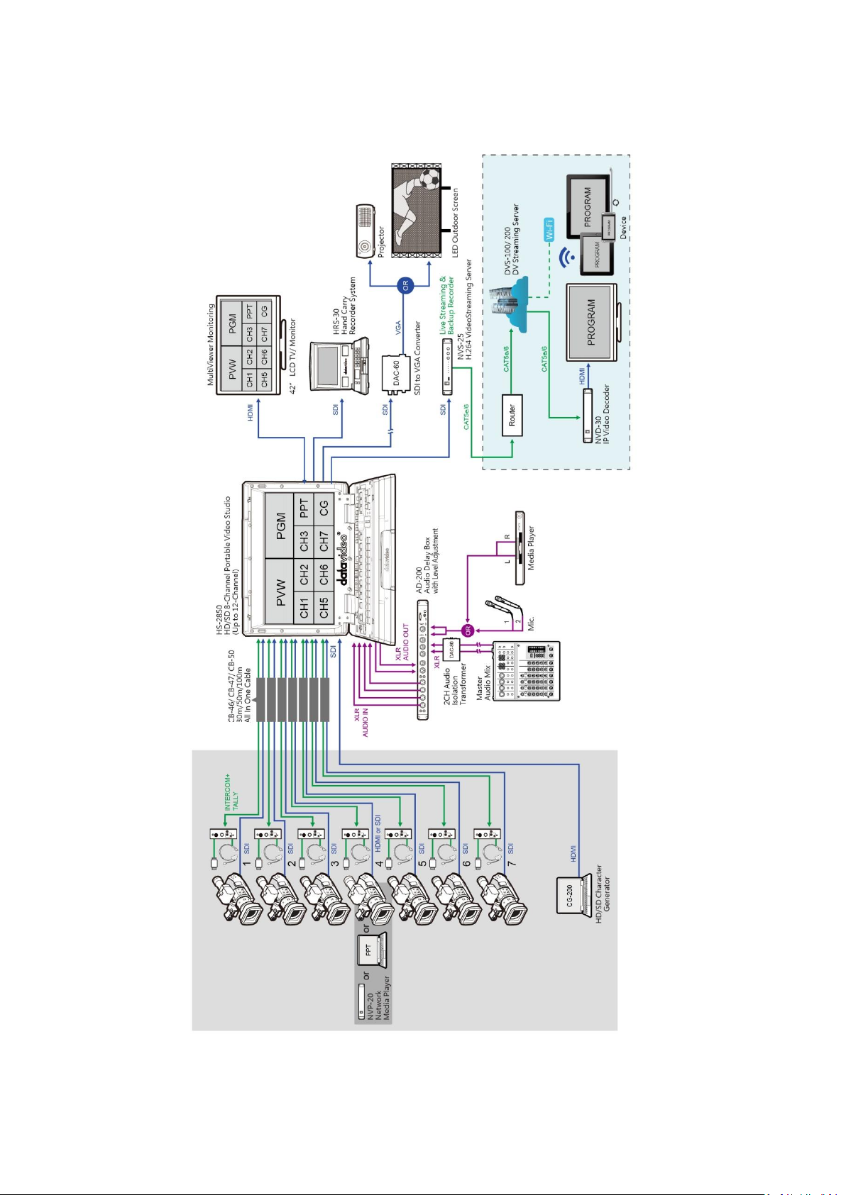
1.2 System Diagram
10
Page 11
Chapter 2 Connections and Controls
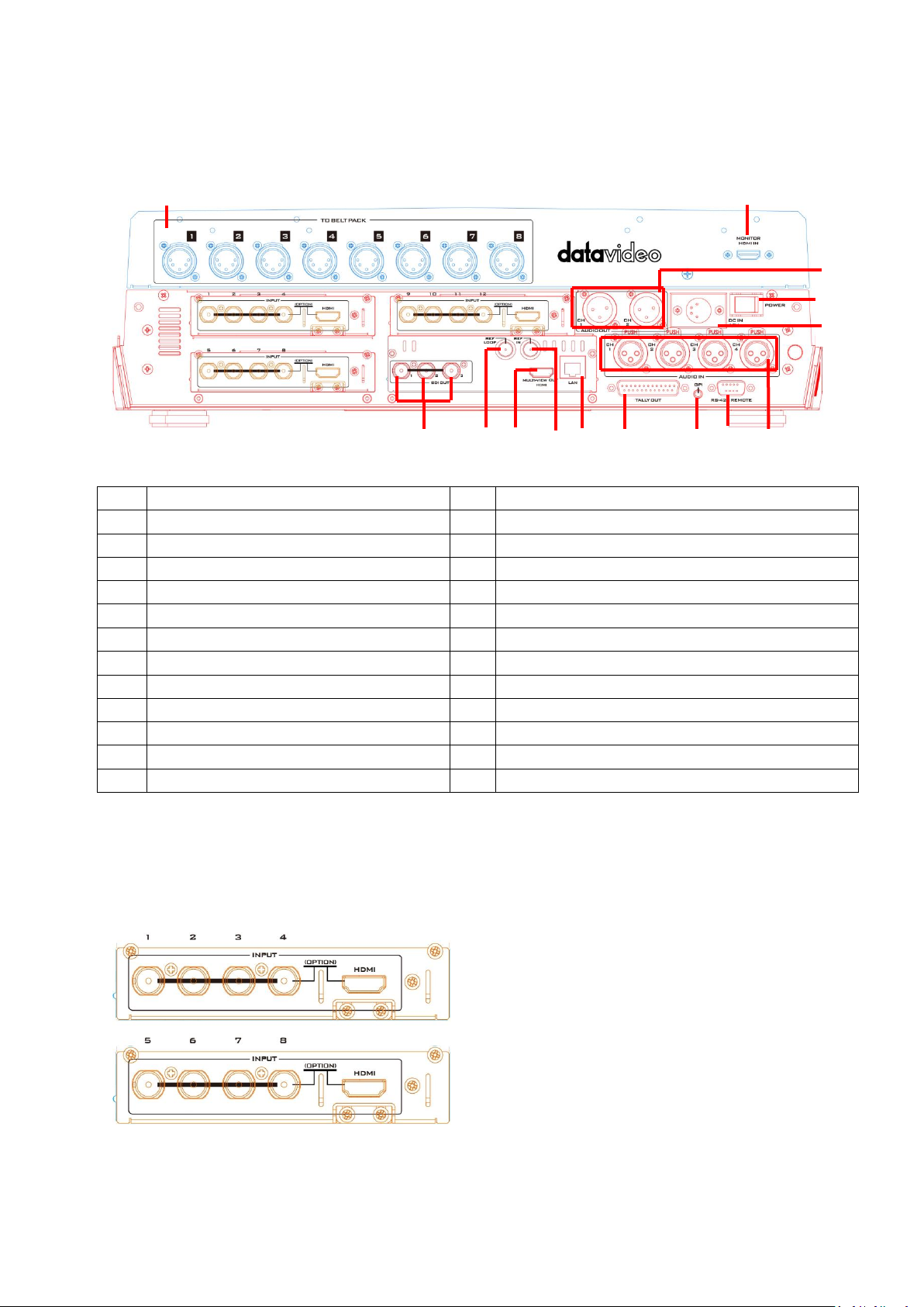
1.
Input 1 – SD / HD-SDI
14.
User Defined SDI Outputs 1~3
2.
Input 2 – SD / HD-SDI
15.
Sync Output / Ref Loop
3.
Input 3 – SD / HD-SDI
16.
User Defined Multi view Output
4.
Input 4 – SD / HD-SDI / HDMI
17.
Ethernet port for PC control & updates
5.
Input 5 – SD / HD-SDI
18.
Tally Output connector
6.
Input 6 – SD / HD-SDI
19.
GPI connector
7.
Input 7 – SD / HD-SDI
20.
RS-422 connector
8.
Input 8 – SD / HD-SDI / HDMI
21.
4pin XLR Power Input connector
9.
Input 9 – SD / HD-SDI**
22.
Power Switch
10.
Input10 – SD / HD-SDI**
23.
3pin XLR Audio Inputs
11.
Input11 – SD / HD-SDI**
24.
3pin XLR Audio Outputs
12.
Input12 – SD / HD-SDI / HDMI**
25.
Monitor HDMI IN (External Video Input)
13.
External Sync Input
26.
To Beltpack
Video Input Modules (1 – 12)
The HS-2850 can be supplied with eight or
twelve video input channels.
An HS-2850 with eight input channels (Input
1 to 8) has two video input modules
installed.
There are four video input channels on each
Video Input Module. Each Video Input
Module (shown left) has the same
connections, four BNC connectors and one
13
14
15
16
17
18
19
20
21
23
24
26
25
2.1 Main Unit – Rear Panel Overview
** Please note inputs 9 to 12 are not present if you have purchased the eight channel HS-
2850. Eight channel units can be upgraded to twelve inputs, please speak with your local
dealer.
2.1.1 Rear Panel Connections
11
Page 12
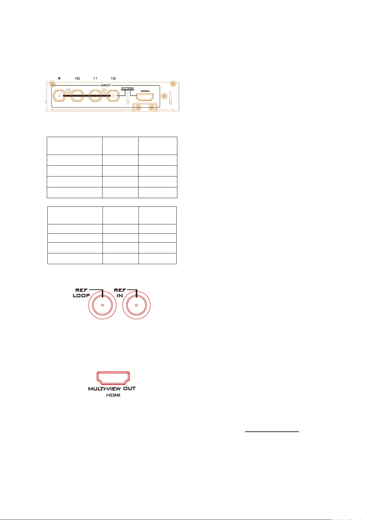
HDMI port. The fourth BNC connector and
the HDMI port are an option for the same
input channel.
An HS-2850 with twelve input channels has
three video input modules installed. An eight
channel unit can be upgraded to twelve
inputs by adding another Video Input
Module (Input 9 to 12).
SD Inputs
SDI
BNC
HDMI
1, 5 & 9
Yes
---
2, 6 & 10
Yes
---
3, 7 & 11
Yes
---
4, 8 & 12
Yes
Yes
1920x1080i
HD Inputs
HD-SDI
BNC
HDMI
1, 5 & 9
Yes
---
2, 6 & 10
Yes
---
3, 7 & 11
Yes
---
4, 8 & 12
Yes
Yes
The two tables, on the left, show which types
of video inputs can be connected to the HS2850 switcher. For example, only input
channels 4, 8 and 12 have the HDMI input
option.
NOTE: This switcher cannot accept 1080P or
1280x720P or 1440x1080i inputs and has no
computer input scaling options.
SYNC I/O (13 / 15)
The HS-2850 can be synchronized with other
studio equipment such as cameras and
House sync. Input BNC (13) will accept House
sync or Tri-level sync. Output BNC (15) can
be used to pass the sync signal to other
studio equipment such as cameras or
recorders.
HDMI MULTIVIEW OUT (16)
The HS-2850 has one HDMI outputs (16)
which can be used to display a preset
combination of inputs plus program and
preset.
See the section on HDMI Multi-View for the
five preset multi-view options.
12
Page 13
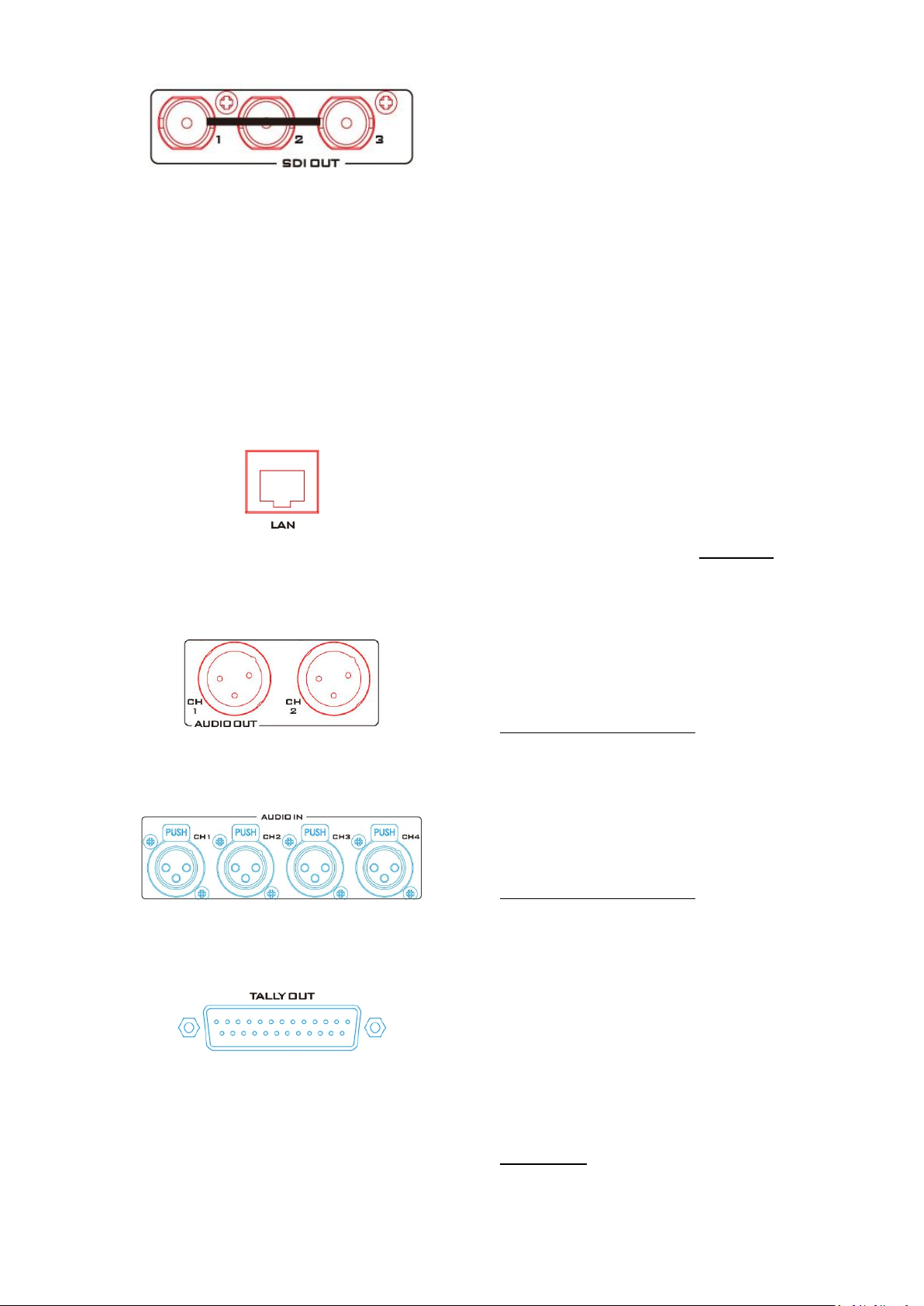
SDI VIDEO OUTPUTS (14)
The three BNC output connectors (14) are
user defined SDI outputs. Each of these SDI
outputs has the option to be:
1. Program output
2. Preview output
3. Program output without logo
4. Program output without logo and DSK
5. Aux output of a selected input channel
SDI outputs 2 and 3 also have the option to
be a Program output which has been
downscaled from HD to SD resolution.
ETHERNET PORT (17)
This RJ45 Ethernet port (17) is used to
connect the HS-2850 to a PC for remote
control, or to update the unit’s firmware, or
to configure the switcher. See Chapter 3 for
more details.
AUDIO OUT (24)
Supports two channels of the XLR Balanced
Audio output.
See Chapter 5 Audio Function for more
details.
AUDIO IN (23)
Supports four channels of the XLR Balanced
Audio Input.
See Chapter 5 Audio Function for more
details.
TALLY OUT (18)
The HS-2850 Tally Output port provides bicolour tally information to a number of other
Datavideo products, such as the ITC-100
eight channel talkback system or the
Datavideo TLM range of monitors.
See Appendix 1 for more details.
13
Page 14
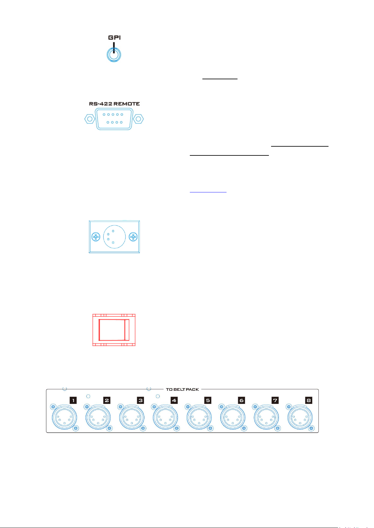
GPI (19)
The GPI socket can be used for simple
external control.
See Appendix 2 for more details.
RS-422 REMOTE (20)
In addition to the Ethernet port for remote
control, you can also connect your PC to this
port for controlling the HS-2850 with the SE
Remote software. See Section 2.2.8 SE
Remote Control Software for details.
Please check with your local Datavideo office
for advice on this connection or refer to
Appendix 4 of this manual for RS-422 PIN
definitions and cable wiring.
DC IN (21)
Connect the supplied 12V 5A PSU to this 4pin
XLR socket.
Pin 1 = GND ( - )
Pin 2 = NC
Pin 3 = NC
Pin 4 = VCC ( + )
Power Switch (22)
The power switch turns ON/OFF the unit.
TO BELTPACK (26)
Intercom Channel Input / Output XLR Sockets
Each of the 8 channels has an XLR connector that carries bi-directional signals between the
ITC-150 and ITC-100SL. All connections are contained within one cable.
14
Page 15
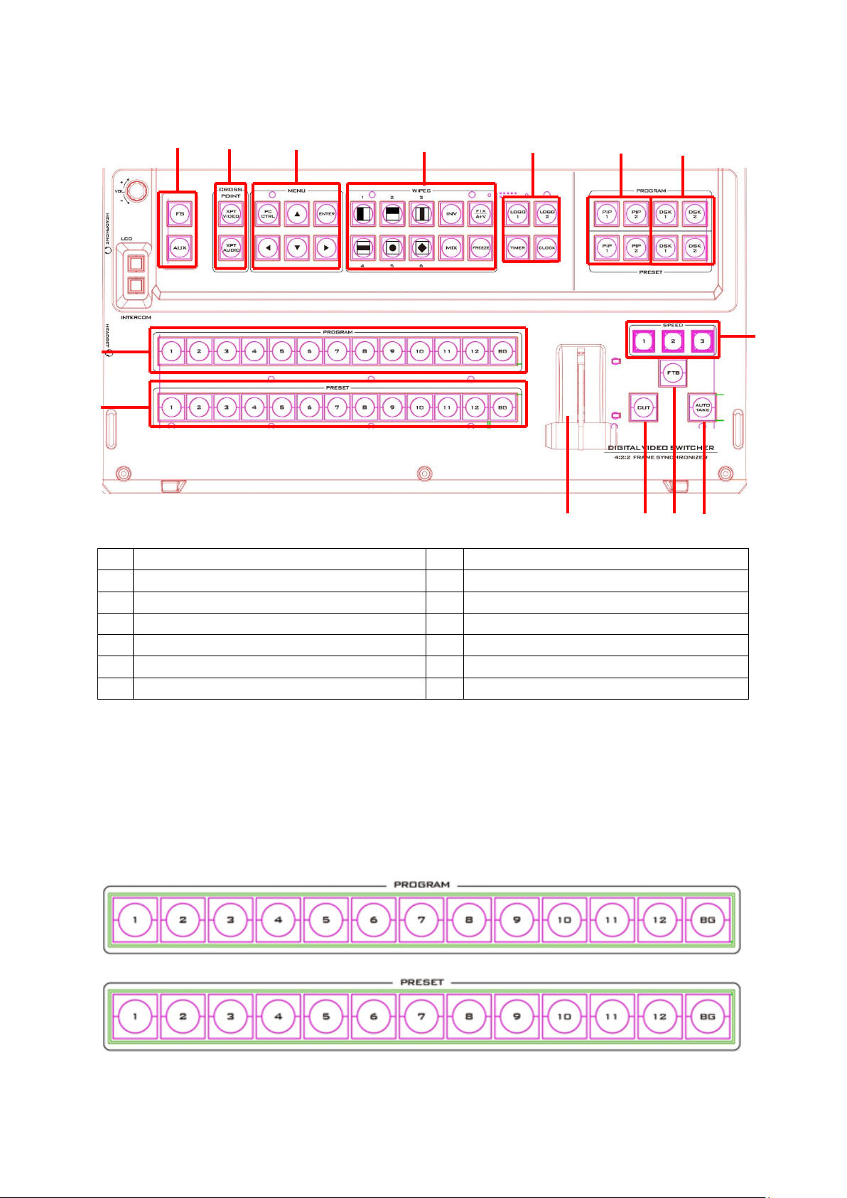
2.2 Control Panel Overview
1.
Frame Store & AUX button
8.
Speed Selection
2.
Crosspoint buttons
9.
AUTO TAKE
3.
PC / Menu control
10.
FTB – Fade To Black
4.
Transition selection
11.
CUT
5.
Logos 1 & 2, Clock & Timer
12.
T-Bar – Manual Transitions
6.
PIP selection PST & PGM
13.
Preset Row (PST)
7.
DSK selection PST & PGM
14.
Program Row (PGM)
1 2 3
4 5 6
7
8 9 10
11
12
14
13
2.2.1 Video Switching
Program and Preset rows
The Program row of buttons is the active channel, this is the live output. The active channel
will appear as the Program Output (PGM). You can switch or CUT from one video source to
another directly on the Program row. You will see the multi view PGM output change as you
press different keys along this top row of buttons.
15
Page 16
The Preset row is the cued channel, this channel will appear in the PST or Preview window.
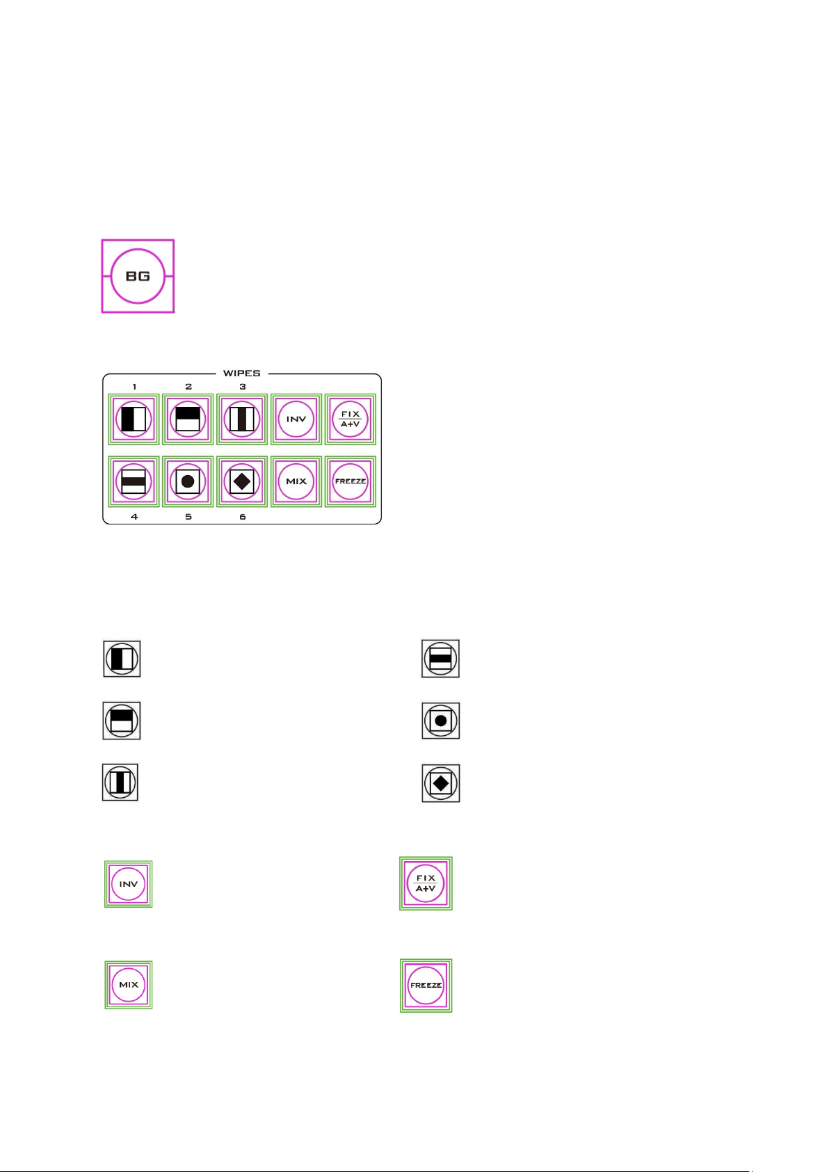
1.
Vertical Wipe Left to Right.
4.
Horizontal Wipes from Centre to
Top and Bottom.
2.
Horizontal Wipe Top to
Bottom.
5.
Circle Wipe from Centre to
outside edges.
3.
Vertical Wipes from Centre to
Left and Right sides.
6.
Diamond Wipe from Centre to
outside edges.
INV
Invert the selected wipe so it
travels in the opposite
direction.
FIX / A+V
Switch the audio mixing option
between Audio Fixed and Audio-F-
Video (A+V).
MIX
Pressing this button selects a
basic A/B Dissolve for the next
transition.
FREEZE
Freeze the program source image or
return to live video of the selected
program source.
The Preset row selection decides which input will be transitioned next when using any of the
transition controls.
Note: The keys on the Program and Preset rows will be inactive while the T-Bar is active or
moving. Only when the T-Bar is fully up or fully down will the keys respond.
Background
The Background button assigns a background colour or SMPTE 75% bars for
use on the Program and Preset row.
2.2.2 Video Transitions
The HS-2850 features six user defined wipe
buttons, an A/B dissolve or MIX button, an INV
or Invert wipes button and a FREEZE button.
All wipes can have an optional colour border
applied. The wipe border width and colour are
chosen within the menu system.
Transitions can be performed manually using the T-Bar or automatically by using the SPEED
and AUTO TAKE buttons.
Transition Selection
16
Page 17
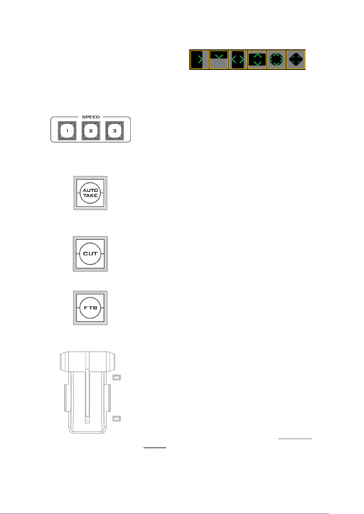
Transition Effect Indication
The selected transition will be indicated
in the status area of the HDMI multiview output. When the INV button is
pressed, the six wipe icons change to
their opposite direction icon.
SPEED
There are three speed buttons which can be defined by the
user. By pressing a speed button the user is choosing the
rate of transition or time taken when using the AUTO TAKE
button.
AUTO TAKE
This performs an automated switch from the current
program source to the selected preset source. The selected
transition wipe or dissolve will also be used. The timing of
the transition is set by the chosen Speed button.
CUT
This performs a simple immediate switch from the current
main source to the selected sub source. The selected
transition wipe or dissolve is not used.
FTB
Fade To Black, this button fades the current video program
source to black. When pressed again it acts in reverse from
complete black to the currently selected program video
source.
T-Bar
This performs a manually controlled transition from the
current program source to the selected preset source. The
selected transition wipe or dissolve will be used. When the
T-Bar has travelled as far as it can go, the transition
between sources is complete. The T-Bar has indicators next
to it, which light when the transition is complete.
The T-Bar can be operated in one of two modes which is
chosen by a menu option, see the section on OSD MENU
options for more details.
Triggering the Transition
17
Page 18

2.2.3 Logo and Clock
The HS-2850 has the ability to store six static logos and one
dynamic logo. The logo files are transferred to the HS-2850
from a Windows PC using the Ethernet connection and the
supplied SEConfig software. See Chapter 3 for more details on
using this software.
LOGO 1
The LOGO 1 and LOGO 2 buttons are used to display pre-
selected logos on the HS-2850 Preset and Program outputs.
When the button is active the selected logo is shown. These logos are selected from the
switcher’s memory and positioned using a menu option see the section on OSD MENU
options for details.
LOGO 2 or CLOCK
The user cannot display LOGO 2 and CLOCK at the same time. Instead use LOGO 1 and
CLOCK together or use LOGO 1 and LOGO 2 together.
The clock time can be synchronized with a computer or set manually using a menu option.
The colour and font used in the clock digits can be changed using the supplied SEConfig
software. See Chapter 3 for more details on using this software or see OSD MENU Options
onwards for the Clock menu options.
TIMER
In some mixing or switching applications it is useful to have a countdown timer. It could be
that the input is a pre-recorded video clip and you need to know when to be ready to switch
away from it.
This countdown timer function is only seen in the status area of the HDMI multi-view output
to the right of the normal Clock function. The timer can be selected for one input channel,
several channels or all channels.
When the TIMER button is active and the user switches to a selected input channel, the
countdown starts on the HDMI multi-view.
The value of the countdown, in minutes and seconds (MM:SS), is set by a menu option.
Whilst the countdown is in progress, T-Bar operation is ignored.
When the countdown reaches zero, the user can then switch or transition to another input
channel. If the countdown reaches zero the switcher will not automatically change to the
selected Preset source.
18
Page 19
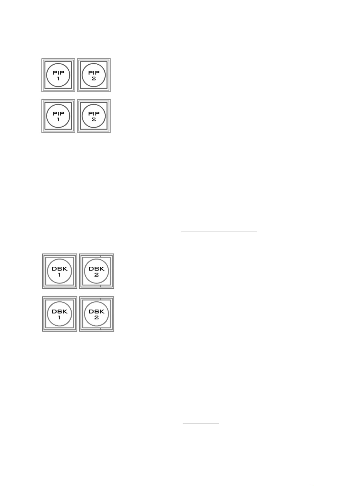
2.2.4 Picture-in-Picture and Downstream Key
PIP Preset and PIP Program
When looking at the top right corner of the HS-2850 Control
Panel / Keyboard there are four PIP keys. These are labelled
Program and Preset. The upper PIP1 and PIP2 keys relate to
activating Picture In Picture images on the Program outputs. The
lower PIP1 and PIP2 keys relate to activating Picture In Picture
images on the Multi-view or Preview outputs.
Assigning a video source input to a PIP
Using the lower PIP1 or PIP2 buttons you can assign a selected
video input to the chosen PIP video layer.
1. First press and hold down the required PIP button on the lower row. The Preset row
of input sources will light.
2. While still holding down the PIP button, press to select the required input from the
Preset row.
3. The input will flash to confirm it is selected.
This selection will also be confirmed on the HDMI Multi-view, with a PiP1 or PiP2 label
shown next to the selected input image.
The full PIP process is described in the section on Picture-In-Picture Function.
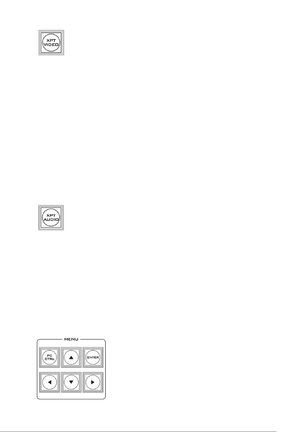
DSK Preset and DSK Program
When looking at the top right corner of the HS-2850 Control
Panel / Keyboard there are four DSK keys. These are labelled
Program and Preset. The upper DSK1 and DSK2 keys relate to
activating Down Stream Keying on the Program outputs. The
lower DSK1 and DSK2 keys relate to activating Down Stream
Keying on the Multi-view or Preview outputs.
Assigning an input to a DSK channel for keying
Using the lower DSK1 or DSK2 buttons you can assign a selected
video input to the chosen DSK video layer.
1. First press and hold down the required DSK button on the lower row. The Preset row
of input sources will light.
2. While still holding down the DSK button, press to select the required input from the
Preset row.
3. The input will flash to confirm it is selected.
This selection will also be confirmed on the HDMI Multi-view, with a T1 or T2 label shown
next to the selected input image.
The full DSK process is described in the section on DSK Settings.
19
Page 20

2.2.5 Frame Store and Audio Control
FS – Frame Store Button
The HS-2850 has eight or twelve video channels, depending on the number of
inputs it has. Each of these channels has its own Frame Store, making a total of
eight or twelve Frame Stores. Each of these Frame Stores can hold one still
image. This still image can be called into the production by using the FS button located at
the top left corner of the HS-2850 Control Panel / Keyboard. The FS button allows the user
to toggle between the still image of the Frame Store or the live video input also connected
to that same video channel.
How to choose live video input or Frame Store
1. First press and hold down the FS button. The Preset row of input sources will light.
2. While still holding down the FS button, press the required input on the Preset row.
3. The input button will flash to confirm the Frame Store is selected.
This selection will also be confirmed on the HDMI Multi-view, with the selected channel
showing the live input or frame store image.
The content of each Frame Store is uploaded to the HS-2850 from a PC. The supplied
SEConfig software is used to do this. The file upload process is described in Chapter 3.
AUX Source Selection
The auxiliary output (AUX) allows you to fix the SDI output onto a particular
input source. The HS-2850 has four user defined SDI outputs, see Section 2.1.1
item 14. One or all of these outputs can be set up as an auxiliary (AUX) output
via a menu option. See OSD MENU Options onwards for details.
The AUX output source can be quickly selected in the following way.
1. First press and hold down the AUX button. The Input 1 and 2 buttons of the Program
row will light up red.
2. While still holding down the AUX button, press either the Input 1 button or the Input
2 button on the Program row.
3. The pressed input button (1 or 2) on the Program row will now flash red along with
one of the input buttons on the Preset row flashing green. The rest of the input
buttons on the Preset row will remain solid green.
4. The green flashing button on the Preset row indicates the selected source of the AUX
output. To change the source, simply press other input buttons.
When you see the selected input button flashing green, your AUX output source is now
assigned and you may release the AUX button to complete the AUX source selection.
2.2.6 Crosspoint
The CROSSPOINT function allows you to cross assign input channels to program/preset row
buttons. Follow the steps outlined below to assign video input channels to the
program/preset row buttons according to your preference.
20
Page 21
XPT Video
Assign video source, and channel settings according to your preference.
Follow the steps outlined as follows:
1. First press and hold down the XPT VIDEO button. The Program row of input
sources will light.
2. While still holding down the XPT VIDEO button, press the required input on the
Program row. This selects the input source.
3. After pressing the required input on the program row, the Preset row of input
sources will light. While still holding down the XPT VIDEO button, press the
required input on the Preset row. This selects the channel button that the input
source is assigned to.
4. Release the XPT VIDEO button, the selected input button will flash to confirm the
selection.
Note: The XPT video function allows you to associate one video input channel to more than
one program/preset row buttons. For example, you can assign video input channel 1 to
multiple channels by pressing the respective channel buttons of the preset row at step 3 of
the above procedure.
The same procedure can be applied to audio channel sources as well. Follow the steps
described below to cross assign audio input channels to program/preset row buttons.
XPT Audio
Assign audio source, and channel settings according to your preference.
Follow the steps outlined as follows:
1. First press and hold down the XPT AUDIO button. The Program row of input
sources will light.
2. While still holding down the XPT AUDIO button, press the required input on
the Program row. This selects the input source.
3. After pressing the required input on the program row, the Preset row of input
sources will light. While still holding down the XPT AUDIO button, press the
required input on the Preset row. This selects the channel button that the input source
is assigned to.
4. Release the XPT AUDIO button, the selected input button will flash to confirm the
selection.
2.2.7 OSD MENU Options
When the ENTER button is pressed the Main Menu list is
displayed on the HDMI 1 Multi-view output.
This section covers the Menu options in the order that they
appear on the HS-2850 HDMI 1 Multi-view. These settings may
also appear in more detail elsewhere in this instruction manual.
Options may vary depending on the firmware version in use.
21
Page 22
Once the chosen setting has been confirmed with the ENTER button it is stored within the
Version Number
Version Number xx.xx where xx.xx is the firmware version number.
Base Standard
1080i50Hz
Tick selection for ON or OFF
1080i60Hz
1080i59.94Hz
Note: When Output Standard & Format is set to the option HD SDI 1080p (25/29/30):
1. The Output will be automatically adjusted to 1080p25Hz if 1080i50Hz is selected for
Base Standard.
2. The Output will be automatically adjusted to 1080p29Hz if 1080i59.94Hz is selected for
Base Standard.
3. The Output will be automatically adjusted to 1080p30Hz if 1080i60Hz is selected for
Base Standard.
Audio Dynamic Range
Audio Dynamic Range
24
18
Audio Tract
EXTERNAL ANALOG AUDIO
Tick selection for ON or OFF
AUDIO PASS THROUGH
On Preview Video Adjustment
Brightness
72 to 184, default 128
Select the input that you want
to adjust in the PVW window.
This is a fine adjustment, the
change happens gradually as
the value is increased or
reduced.
Contrast
36 to 92, default 64
Saturation
36 to 92, default 64
Aperture
0 to 3
Y-C Delay
0 to 7
Set to Norminal
Reset to default values
Video Input Standard and Format
Inputs 1,2,3,5,6,7,9,
10&11
Can be a choice of:
HD SDI 1080i *
HD SDI 1080p (50/59/60Hz) *
HD SDI 1080p (25/29/30Hz) *
HD SDI 720p (50/59/60Hz) *
SD SDI 4:3
SD SDI 16:9
Inputs 4,8 &12
Can be a choice of
HD SDI 1080i *
HD SDI 1080p (50/59/60Hz) *
HD SDI 1080p (25/29/30Hz) *
HD SDI 720p (50/59/60Hz) *
SD SDI 4:3
SD SDI 16:9
HD HDMI 1080i
HD HDMI 1080p (50/59/60Hz)
HD HDMI 1080p (25/29/30Hz)
HD HDMI 720p(50/59/60Hz)
switchers non-volatile memory.
22
Page 23
SD HDMI 4:3
SD HDMI 16:9
HDMI COLOR MODE: RGB / YUV 4:2:2 / YUV 4:4:4 / CG-200
MODE
*All HD inputs are natively 16:9 aspect ratio.
On Preview Audio Level and Delay
Level
Range +60 to -60
AUDIO DELAY
Range 0 to 16
Nominal
Resets value to 00
SDI De-Emb. Audio Group / Pair
Input 1 – 12
User choice of
GROUP: 1-4
PAIR: 1-2
HDMI De-Emb. Audio Group
Input 4 / 8 / 12
User choice of GROUP 1 / 2 / 3 / 4
Outputs SDI Re-Emb. Group
Output 1 / 2 / 3 /4
User choice of GROUP 1 / 2 / 3 / 4
Auto Audio Mixing Type
X-Type
Tick selection / X type = A/B cross fade
V-Type
Tick selection / V type = Fade out A then Fade in B
T-Bar Audio Mixing Type
Follow Auto (X or V) Type
Tick selection / use the option enabled in Auto Audio Mixing
Type
By the End
Tick selection / clean cut or immediate audio switch
PIP Set Up
Position PIP 1
Horizontal Position (Left to
Right)
000-097
Vertical Position (Lower to
Upper)
000-108
Size PIP 1
1 (Small) – 33 (Large)
Border PIP 1
Width
00-05
Color
1-8
1=White, 2=Yellow, 3=Cyan,
4=Green, 5=Magenta,
6=Red, 7=Blue, 8=Black
Position PIP 2
Horizontal Position (Left to
Right)
000-097
Vertical Position (Lower to
Upper)
000-108
Size PIP 2
1 (Small) – 33 (Large)
Border PIP 2
Width
00-05
Color
1-8
1=White, 2=Yellow, 3=Cyan,
4=Green, 5=Magenta,
6=Red, 7=Blue, 8=Black
Logo Set Up
Logo 1
Select
01-08
Logo selection 1 to 7 are still
23
Page 24
image
Logo 8 selection is dynamic
moving image
Horizontal Position (Left to
Right)
000-110
Vertical Position (Lower to
Upper)
000-135
Logo 2
Select
01-08
Logo selection 1 to 7 are still
image
Logo 8 selection is dynamic
moving image
Horizontal Position (Left to
Right)
000-110
Vertical Position (Lower to
Upper)
000-135
Speed Button Set Up
Speed 1
1-64 (Frames)
Speed 2
1-64 (Frames)
Speed 3
1-64 (Frames)
Wipe Button Set Up
Button 1-6
WIPE
1-8
Soft Edge
0-4
Color
1-8
1=White, 2=Yellow, 3=Cyan,
4=Green, 5=Magenta,
6=Red, 7=Blue, 8=Black
Outputs Mode and Standard
Output 1/2/3/4
Standard & Format
HD SDI
SD SDI 4:3
SD SDI 16:9
HD SDI 1080p (25/29/30)
Mode
Program
Program logo free
Program logo & DSK free
Preview
AUX 1
AUX 2
DSK Set Up
DSK 1 / 2
Fill & Key mode
Alpha channel
Luma Key mode
Luma Key level
0 (black) to 255 (white)
BG Color (1-8) and Color Bar (9)
1-9
Background Color Settings
1=White, 2=Yellow, 3=Cyan, 4=Green, 5=Magenta, 6=Red,
7=Blue, 8=Black, 9 = SMPTE 75% colour bars
T-Bar Mode
One Way Mode
= T-Bar operates transition in only one direction
24
Page 25
Two Way Mode
= T-Bar operates transition in both directions
1kHz to Color Bar
1kHz to Color Bar
Tick selection for ON or OFF
Keys Brightness
1-4
Keyboard button brightness with user choice of 1 to 4
1 = Low, 4 = High
Multi-Screen Audio Indicators
Multi-Screen Audio
Indicators
Tick selection for ON or OFF
Reference
External
Reference
Tick selection for ON or OFF
Mode
HD: Analog 3 Level Signal
Tick selection for ON or OFF
SD: Composite Signal
Tick selection for ON or OFF
H-Timing
0-255
Factory Settings
Factory Settings
Tick selection for ON or OFF
Resets to factory default
Clock Settings
Horizontal Position (Left
to Right)
000-110
Vertical Position (Lower
to Upper)
000-124
SET Hours
0-23
SET Minutes
0-59
Clear Seconds
Tick selection for clearing second
Multi Screen Mode
This option relates to the HDMI outputs 1 and 2.
A: M1=PVW+PGM+3 IN; M2=9 IN
B: M1=PVW+PGM+12 IN; M2=PGM
C: M1=PVW+PGM+8 IN; M2=PGM
D: M1=PVW+PGM+12 IN; M2=M1
E: M1=PVW+PGM+8 IN; M2=M1
GPI Settings
Input Select
00-12
Chosen input number
Time Delay
In frames between 1 to 75
Mode
Level Mode
Tick selection for ON or OFF
Pulse Mode
Tick selection for ON or OFF
Countdown Timer Settings
Input 1-12
Count Down Enable
Each input can be selected
for Count Down ON or OFF.
Down Counter Value
If Count Down is ON then
the Down Counter value is
set in minutes and seconds
(MM:SS) - Max.= 1 Hour or
60:00, Default = 15 Seconds
or 00:15
Multi-Screen Audio Source
Preview
Tick selection of Program or Preview audio on the HDMI
outputs
Program
25
Page 26
Control Interface
Ethernet
Tick selection for ON or OFF
RS422
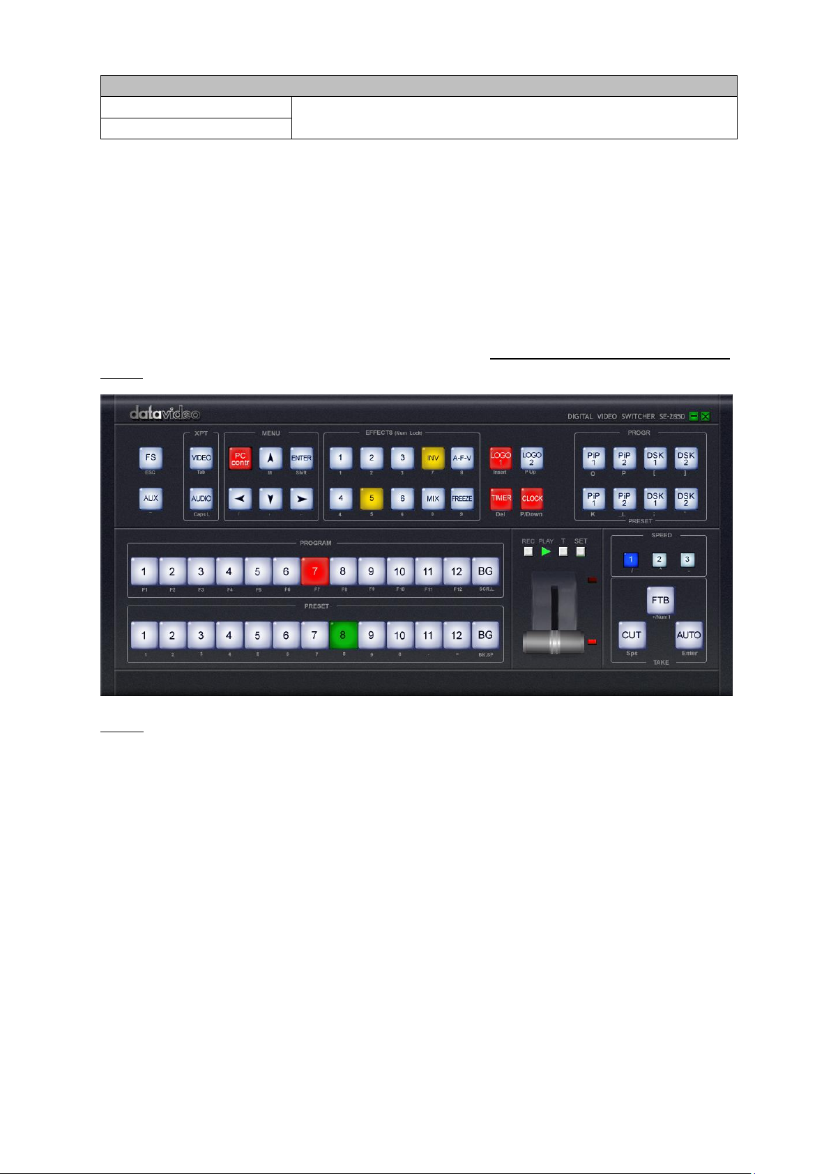
2.2.8 PC Control – SE Remote Control Software
It is possible to control the HS-2850 with a Windows 7 computer using an Ethernet
connection. The SE Remote software supplied with the switcher needs to be installed on the
computer first. The HS-2850 then needs to be placed into PC Control mode. To do this press
the PC Control button on the HS-2850 Control Panel. Once launched, the Remote software
displays an image of the HS-2850’s keyboard as shown below. Any active functions or
selections will be shown with a red button or key. These buttons or keys can be clicked with
a mouse or alternatively you could use a touch screen monitor.
Before launching the SE Remote software, please see Chapter 3 Switcher Configuration
Utility for network setup information.
NOTE: It is not possible to run both the SEConfig and SE Remote software applications at the
same time.
SET Function
After the network connection between the PC and the HS-2850 is successfully configured,
you can then launch the SE Remote software on the PC. Locate SET function button which is
located just above the T-Bar. When clicked, a new window will open as shown left below.
This Settings window is used to match the software to the IP address of the connected HS2850 switcher.
26
Page 27

Enter the switcher’s IP address and then click the “Check” button to determine the switcher
model number which is then selected from the “Model” pull-down menu. Once configured,
click the OK button to shut down to “Settings” window and the SE Remote software should
be successfully connected to the HS-2850 as shown in the diagram below.
REC & PLAY Functions
Left mouse click the grey REC button and it will light up red. All of your actions when using
the Remote Console will now be recorded to file. The only action that will not be recorded is
the T-Bar, use the CUT or AUTO TAKE buttons instead. The function buttons just above the
T-Bar as listed on this page are also ignored.
Click the red REC button again and a save window will appear. You can now save the
recorded actions as a macro text file to a chosen location on the computer.
Click the grey PLAY button and a load file window will appear. You can now browse to and
load a macro text file. When you load a file the recorded actions will begin to play back until
the end of the file.
27
Page 28

Software-based Macro Functions
Intercom Function
Monitor Function
USB Port
USB port for LED power supply and Firmware Upgrade.
XLR Microphone Socket
Combined XLR / ¼” (6.3mm) Jack Microphone Input for
either a Condenser or Dynamic Gooseneck
Microphone.
XLR supports Condenser Microphones
¼” (6.3mm) Jack supports Dynamic Gooseneck
Microphone
ALL Button
Opens communication with all channels. All channels
will hear communication from the operator, or from
any other channel using the TALK button.
It is possible to record a Macro type playlist to the computer when using the SE Remote
software. This Macro function allows these pre-recorded keyboard actions or selections to
be played back within a project where timing is important or where the same steps are
repeated throughout the production. The Macro function buttons are REC, and PLAY. These
buttons are located just above the T-Bar in the SE Remote display above.
TIME Function
This button is located just above the T-Bar in the SE Remote display above. Mouse clicking
on the TIME button will synchronize the time on the HS-2850 switcher to the current time
on the computer.
2.3 Intercom & Monitor Control Panel
2.3.1 Intercom Function
28
Page 29

Channel Buttons 1~8
Opens communication with individual channels. More
than 1 channel can be active at any given time, active
channels are illuminated red.
All active channels will hear any communication from
the operator or from any other active channel.
The buttons will also indicate if any channel is paging,
the paging channel will flash in orange until the page is
answered.
MUTE Button
Mutes all communication from the base station or any
channel.
2.3.2 Monitor Function
HDMI, Multiview, PROGRAM
Select the type of input you are using - HDMI, Multiview,
PROGRAM.
The active input will be indicated by a red LED on the Source
Button. When you push the “HDMI” button, you select the 17.3"
display from the HDMI source input of Rear Panel; it is a full
screen display. When you push the “MV” button, then you go
back to show multi-view so you can switch back & forth between
HDMI & Multiview.
BLUE
Press this button to eliminate the red and green component of
input signals. Only the blue component of an input is displayed
on the screen.
PATTERN
Press the PATTERN Key to activate the colour bar.
ZOOM
The ZOOM Feature Setting Menu allows you to adjust the screen
display size.
29
Page 30

Menu Navigation Buttons
Display and navigate the set up menus - See Menu Options for
more details
UP Button also switches the 4:3 Mask On / Off - (only available in
16:9 modes)
Aspect Ratio Button
Sets the Aspect Ratio to 16:9 / 4:3
Mute Button
Mutes the audio from the internal speakers or headphone
socket.
Volume Control & Audio Meter
Adjusts the speaker / headphone volume up / down.
PWR
Switches the TLM-170 Power ON / OFF.
2.3.3 Monitor Menu Options
Main Options
Sub Options
Parameters
Parameters
MAIN ADJUST
BRIGHTNESS
0~100
CONTRAST
0~100
SHARPNESS
0~100
SATURATION
0~100
TINT
0~100
BACK LIGHT
0~100
NR
HIGH / MID / LOW / OFF
MPEG NR
HIGH / LOW / OFF
The HS-2850 Monitor is set up via on screen menus. To display the on
screen menu, press the MENU button.
The menus are navigated using the Up / Down buttons.
Press Enter button to enter or exit the menu mode.
30
Page 31

VOLUME
0~100
EXIT
COLOR Adjust
7500
9300
6500
USER COLOR
RED
0~100
GREEN
0~100
BLUE
0~100
EXIT
SCAN SETTING
UNDER SCAN
OVER SCAN
INFORMATION
H. FREQUENCY
V. FREQUENCY
RESOLUTION
VER.
LANGUAGE
English [default]
Francis
Deutsch
Español
Italiano
Dutch
Português
Russian
EXIT
SPECIAL
FUNCTION
OSD TIMEOUT
5-120 SEC
FRAME RATIO
90 / 80 / 0FF
4:3 MARK LINE
ON / OFF
CENTRAL MARK
ON / OFF
CINEMA ZONE MARK
ON / OFF
AUDIO CHANNEL L*
1/2/3/4
AUDIO CHANNEL R*
1/2/3/4
EXIT
FACTORY RESET
EXIT
* Selectable on PGM only; external HDMI and MV are allowed on 1 and 2 ONLY
MAIN ADJUST
The first menu to be displayed is the MAIN ADJUST Menu.
To access the MAIN ADJUST Menu press enter, the Brightness setting will be highlighted.
To adjust the Brightness press Enter again. Use the Up / Down buttons to change the setting
and then press Enter to store the new value and return to the main menu.
To select a different setting (Brightness, Contrast, Saturation, Sharpness, TINT), use the Up /
Down buttons. Follow the same procedure to set other values.
31
Page 32

COLOR
To access the menu press enter so that Color Adjust option is highlighted
To access the option for the selected color setting, press enter again.
Use the Up / Down buttons to navigate the available color settings.
You can choose:
7500
9300
6500
USER COLOR
Once selected, the information will be displayed as follows:
You will see:
H. FREQUENCY
33.7KHZ
V. FREQUENCY
60.0HZ
RESOLUTION
1920X1080I
VER.
0.11
To access the options for the selected setting press enter again, so that the option is
highlighted
Use the Up / Down buttons to navigate the available options.
You can choose:
OSD TIMEOUT
5-120 SEC
FRAME RATIO
90 / 80 / 0FF
4:3 MARK LINE
ON / OFF
CENTRAL MARK
ON / OFF
CINEMA ZONE MARK
ON / OFF
AUDIO CHANNEL L*
1/2/3/4
AUDIO CHANNEL R*
1/2/3/4
Information
The System Information Menu displays Horizontal Frequency, Vertical Frequency,
Resolution and the Firmware Version of the monitor.
Special Function
The Special Function Menu has settings for the OSD TIMEOUT, Frame Ratio, 4:3 MARK LINE,
Central Mark, Cinema Zone Mark and Audio Channel L & R.
32
Page 33

Factory Reset
The monitor menu offers a Factory Reset option, which will return all the settings of the
monitor to the factory defaults
To reset the monitor press the MENU button and then use the UP / Down button to
navigate to FACTORY RESET option. Press ENTER again to reset the monitor. After a few
seconds the monitor will be reset.
33
Page 34

Chapter 3 Switcher Configuration Utility (SEConfig Software)
The Switcher Configuration Utility or the SEConfig Software allows you to configure the HS2850 with a Windows 7 computer using an Ethernet connection. Before launching the
Switcher Configuration Utility, make sure it is installed on your computer.
3.1 Network Setup
Before you attempt to establish connection between PC and your HS-2850, you have to
manually configure the PC network settings first. Follow the steps outlined below to assign a
static IP address to your PC.
(1) Connect the PC to the HS-2850 switcher using an Ethernet cable.
(2) Turn on the PC and the HS-2850.
(3) The HS-2850 then needs to be placed into PC Control mode. To do this press the PC
Control button on the HS-2850 Control Panel or keyboard.
(4) Find the switcher’s IP address using the SEConfig software. Double click the SEConfig
software icon to open the Switcher Configuration Utility program.
(5) The Find button within the SEConfig software will help confirm the IP address of the
switcher. See later sections in this Chapter for more information on SEConfig. In the
example below, the IP address of the switcher is 192.168.0.101.
(6) Once you have obtained the switcher’s IP address, go to Control Panel, open Network
and Sharing Center and then click Ethernet.
34
Page 35

(7) On the Ethernet Status Window, click the Properties button.
(8) On the Ethernet Properties window, double click Internet Protocol Version 4 (TCP/IPv4)
to open a window on which you will be allowed to manually enter an IP address for
your PC.
35
Page 36

(9) Please remember that the PC used must be in the same IP network as the HS-2850. So
the first three octets (numbers) in the IP Address field must match the first three octets
of the switcher IP address. The fourth octet should be a different number for the PC
and switcher. In the example below, we have entered an IP address of 192.168.0.100
with the Subnet Mask of 255.255.255.0.
36
Page 37

Note: To reset the IP Address of the PC/laptop use the Network and Sharing Center option
1. Double click the SEConfig DV icon to launch the application.
2. If you immediately get an error
window, do not worry, this just means
the “PC Control” button in the MENU
area of the HS-2850 keyboard has not
been enabled.
3. Make sure the “PC Control” button is
enabled and then click OK.
4. Select Ethernet to display the
Computer’s IP Address. Click the Find
button to find and display the HS-2850
Switcher’s IP Address in the drop down
list. The first three numbers in both IP
addresses should match. See the
example on the left.
in Windows 7 Control Panel. Click on Local Area Connection then Properties. Click to
highlight Internet Protocol Version 4 (TCP/IPv4) then click Properties again. Then click Use
the following IP address.
3.2 Connecting the SEConfig Software to the Switcher
37
Page 38

5. Click Connect and additional function
tabs will immediately become available
at the top of the application window.
These are:
Switcher
Settings
Images Upload
M/V Input Source Labels
M/V Layout
M/V ‘A’ Upload
M/V ‘B’ Upload
M/V ‘C’ Upload
3.2.1 Change the Switcher IP Address
The Switcher Network Setup Utility allows the user to change the switcher IP
address. Locate, on your desktop, the icon as shown in the diagram below and
then double click it to open the utility software.
After the Switcher Network Setup Utility is opened, you will see the following SE Network
Setup window on the screen.
To change the IP address, click the Setup button to display the Network Parameters as
shown in the diagram below. Update the network parameters accordingly.
38
Page 39

Use the network PING feature to check if the IP change is successful. You will get the PING
reply from the switcher if the IP is valid and the connection has been successfully
established.
3.3 Switcher tab
This first tab can be used to choose the method of connection between the computer and
the switcher. In this case the HS-2850 is connected using selected Ethernet IP addresses.
Note that the first three numbers in the IP addresses of the switcher and computer should
be the same. The last number in each IP address should be unique.
If you are connecting for the first time you may be asked by the computer to change the
firewall setting to allow this application to connect to the switcher.
39
Page 40

3.3.1 Profiles
Video Adjustment
This is fine tune
adjustment, the change
occurs gradually as the
value is increased or
Brightness
-56 - +56
Contrast
-28 - +28
Saturation
-28 - +28
YC Delay
-4 - +3
Aperture
0 - 3
It is possible to store the current profile or settings of the switcher to your computer. This
file can then be restored to the machine at a later date allowing simple configuration of the
unit. Depending on the included levels of the profile this save process may take some time
to complete.
3.4 Settings tab
The settings tab is another way to change the menu settings of the switcher. The options
may appear in a slightly different order from those in the onscreen menu described in
Section 2.2.7.
Each menu option in the left hand pane can be expanded by clicking on the plus sign in the
left hand pane. The right hand pane shows any values which can be changed.
3.4.1 Inputs tab
The Input settings of inputs 1 to 12 can thus be configured from the computer. Clicking the
Inputs tab will display a list of various input settings.
Note due to the design of the switcher, different inputs (SDI or HDMI) may have more or
less options as they are not all the same. See Rear Panel Connections.
40
Page 41

decreased.
Audio Adjustment
This is fine tune
adjustment, the change
occurs gradually as the
value is increased or
decreased.
Audio Level
-60 - +60
Audio Delay
0 - 17
Option of Input
All HD inputs are natively
16:9 aspect ratio.
Type, Format, Aspect and
Definition
SDI SD 4:3
SDI HD 1080i
SDI SD 16:9
SDI HD 720p
SDI 3G 1080p
SDI HD 1080p
SDI De-Embedded Audio
Group and Pair
User choice of Group
1/2/3/4 and Pair 1/2
Audio Group
Audio group 1 / 2 / 3 / 4
Stereo Pair
Stereo pair 1 / 2
Countdown
Each input can be selected
for Countdown ON or OFF.
If Countdown is ON then
the Down Counter value is
set in minutes and seconds
(MM:SS) – MAX. = 1 Hour or
60:00, and Default = 15
Seconds or 00:15.
Timer Enable
ON / OFF
Countdown Duration
1 – 3600
Options in the table below will be available for HDMI inputs.
HDMI Color Mode
User choice of HDMI Color
Modes
RGB
YUV 4:2:2
YUV 4:4:4
HDMI De-Embedded Audio
Pair
User choice of Pair 1/2/3/4
HDMI Audio Pair
Stereo Pair 1
Stereo Pair 2
Stereo Pair 3
Stereo Pair 4
3.4.2 Audio Tab
The Audio settings of inputs 1 to 12 can be configured from the computer. Clicking the
Audio tab will display a list of various audio settings as shown in the diagram below.
41
Page 42

Audio Tract Mode
External Analog Audio
Audio Pass Through
Audio Dynamic Range
-18 dBFS / -24dBFS
T-Bar Audio Switching
Mode
As selected Audio Mixing
Type
User choice of Audio Mixing
Type (X or V) or Clean Cut
after the T-Bar reaches the
Limit Switch.
T-Bar reaches the Limit
Switch
Audio Mixing Type
Type V
User choice of X type (A/B
cross fade), V type (Fade out
A then Fade in B)
Type X
Audio XPT
Any of input audio
sources can be associated
with any of input button
(or buttons). Different
video sources with the
same audio.
Audio source from Input 1 to:
Audio source from Input 1 to:
Button 1
Button 2
Button 3
Button 4
Button 5
Button 6
Button 7
Button 8
Audio source from Input 2 to:
Audio source from Input 2 to:
Button 1
Button 2
Button 3
Button 4
Button 5
Button 6
Button 7
42
Page 43

Button 8
Audio source from Input 3 to:
Audio source from Input 3 to:
Button 1
Button 2
Button 3
Button 4
Button 5
Button 6
Button 7
Button 8
Audio source from Input 4 to:
Audio source from Input 4 to:
Button 1
Button 2
Button 3
Button 4
Button 5
Button 6
Button 7
Button 8
Audio source from Input 5 to:
Audio source from Input 5 to:
Button 1
Button 2
Button 3
Button 4
Button 5
Button 6
Button 7
Button 8
Audio source from Input 6 to:
Audio source from Input 6 to:
Button 1
Button 2
Button 3
Button 4
Button 5
Button 6
Button 7
Button 8
Audio source from Input 7 to:
Audio source from Input 7 to:
Button 1
Button 2
Button 3
Button 4
Button 5
Button 6
Button 7
Button 8
Audio source from Input 8 to:
Audio source from Input 8 to:
Button 1
Button 2
43
Page 44

Button 3
Button 4
Button 5
Button 6
Button 7
Button 8
3.4.3 Video XPT Tab
Video XPT
Any of video sources can
be associated with any of
Console 1-8 buttons.
Video from Input 1 to:
Video from Input 1 to:
Button 1
Button 2
Button 3
Button 4
Button 5
Button 6
Button 7
Button 8
Video from Input 2 to:
Video from Input 2 to:
Button 1
Button 2
Button 3
Button 4
Button 5
Button 6
The user can also set the Input Video Crosspoints from the computer. Clicking the Video XPT
tab will display a list of configurable video inputs as shown in the diagram below.
44
Page 45

Button 7
Button 8
Video from Input 3 to:
Video from Input 3 to:
Button 1
Button 2
Button 3
Button 4
Button 5
Button 6
Button 7
Button 8
Video from Input 4 to:
Video from Input 4 to:
Button 1
Button 2
Button 3
Button 4
Button 5
Button 6
Button 7
Button 8
Video from Input 5 to:
Video from Input 5 to:
Button 1
Button 2
Button 3
Button 4
Button 5
Button 6
Button 7
Button 8
Video from Input 6 to:
Video from Input 6 to:
Button 1
Button 2
Button 3
Button 4
Button 5
Button 6
Button 7
Button 8
Video from Input 7 to:
Video from Input 7 to:
Button 1
Button 2
Button 3
Button 4
Button 5
Button 6
Button 7
Button 8
Video from Input 8 to:
Video from Input 8 to:
Button 1
45
Page 46

Button 2
Button 3
Button 4
Button 5
Button 6
Button 7
Button 8
Note: In the HS-2850, each input source must be associated with only one button. If you
AUX Source
AUX 1 Source
1 – 12
AUX 2 Source
1 – 12
Clock Position
X-Position = Left to
Right; Y-Position =
Lower to Upper; Set
Hours; Set Minutes;
Clear Seconds
Clock X
0 – 110
Clock Y
124 – 0
Console
T-Bar Mode
One Way
T-Bar operates
transition in only
one direction.
associate one source to more than one button, corrupted small windows will appear on the
HS-2850 Multiview display. To avoid this please make sure your XPT setting is configured to
one input to one button arrangement.
3.4.4 Common Setup
The Common Setup tab will allow you to set up various image effects such as the logo, DSK
and PiP, as well as WIPE transition effects.
46
Page 47

Two Way
T-Bar operates
transition in both
directions.
Keys Brightness
1 – 4
BG Key Setup
(Palette + BARS)
Color 1
User choice of
background color
from 1 to 9. By
default, color is 1.
1 = White; 2 =
Yellow; 3 = Cyan; 4 =
Green; 5 = Magenta;
6 = Red; 7 = Blue; 8 =
Black; 9 = SMPTE
75% Color Bars.
The color can be
changed in the
Palette setup.
Color 2
Color 3
Color 4
Color 5
Color 6
Color 7
Color 8
BARS
1kHz Audio Test
to BARS
1kHz to BARS is ON
When BG Color
setting is 9 (BARS),
1kHz tone can be ON
or OFF.
1kHz to BARS is OFF
Speed Buttons
Preset
Run time of
effects: Min. = 4
Frames
(maximum
speed); Max. = 64
Frames
(minimum
speed).
Run time of effects
for Button 1
4-100
Run time of effects
for Button 2
4-100
Run time of effects
for Button 3
4-100
DSK
HS-2850 has FILL and
KEY model (alpha
channel) and LUMA
KEY mode 0 (black) to
255 (white).
DSK 1
DSK 1 Mode
Luma Key mode
Fill and Key mode
Luma Key 1
Threshold Level
0 – 255
DSK 2
DSK 2 Mode
Luma Key mode
Fill and Key mode
Luma Key 2
Threshold Level
0 – 255
External Clocking
Reference Enable
Checkbox
Reference Mode
CVBS PAL
3 Level Sync
H-timing
0 – 255
GPI
GPI Input
1 – 12
GPI Delay
0 – 75
GPI Mode
Level Mode
Pulse Mode
Logos
Logo 1
Logo 1 Picture
1 – 8
47
Page 48

X Position = Left to
Right; Y Position =
Lower to Upper;
Options 1 to 8. Logo
options 1 to 7 are still
images. Logo 8 is
dynamic moving
image.
Logo 1 X
0 – 110
Logo 1 Y
124 – 5
Logo 2
Logo options 1 to
7 are still images.
Logo 8 is dynamic
moving image.
Logo 2 Picture
1 – 8
Logo 2 X
0 – 110
Logo 2 Y
124 – 5
Palette
Common palette for all
colors used in Wipes /
Border / Background
/ PiP Border.
By default, 75% YCbCr
Color Bar from White
(Color 1) to Black
(Color 8).
Any Palette Color can
be changed by user.
Get Color 1
Get Color 2
Get Color 3
Get Color 4
Get Color 5
Get Color 6
Get Color 7
Get Color 8
PiP
User choice of position,
window size, border
width, and border
color from 1 to 9. By
default the color is 1.
1 = White; 2 = Yellow; 3
= Cyan; 4 = Green; 5 =
Magenta; 6 = Red; 7 =
Blue; 8 = Black; 9 =
SMPTE 75% Color Bars.
The color can be
changed in the Palette
setup.
PiP 1
PiP X-Axis Position
0 – 97
PiP Y-Axis Position
108 – 0
Picture Size
33 – 1
Border Width
0 – 5
Border Color
1 – 8
PiP 2
PiP X-Axis Position
0 – 97
PiP Y-Axis Position
108 – 0
Picture Size
33 – 1
Border Width
0 – 5
Border Color
1 – 8
PiP Border Color
Density
Color 1 Density
0 – 15
Color 2 Density
0 – 15
Color 3 Density
0 – 15
Color 4 Density
0 – 15
Color 5 Density
0 – 15
Color 6 Density
0 – 15
Color 7 Density
0 – 15
Color 8 Density
0 – 15
WIPES
User choice of Wipe 1
to 8; Soft Edge 0 to 4;
Border Colour from 1
to 8. By default, color is
1.
1 = White; 2 = Yellow; 3
= Cyan; 4 = Green; 5 =
Magenta; 6 = Red; 7 =
Blue; 8 = Black; 9 =
SMPTE 75% Color Bars.
WIPES 1
Effect
1 – 8
Border Width
1 – 5
Border Color
1 – 8
WIPES 2
Effect
1 – 8
Border Width
1 – 5
Border Color
1 – 8
WIPES 3
Effect
1 – 8
Border Width
1 – 5
Border Color
1 – 8
WIPES 4
Effect
1 – 8
Border Width
1 – 5
48
Page 49

The color can be
changed in the Palette
setup.
Border Color
1 – 8
WIPES 5
Effect
1 – 8
Border Width
1 – 5
Border Color
1 – 8
WIPES 6
Effect
1 – 8
Border Width
1 – 5
Border Color
1 – 8
3.4.5 Outputs Tab
Output 1
Source to Output
Program
Program Logo Free
Program Logo and Titles Free
Preview
AUX 1
AUX 2
Format: HD; SD; SD 16:9
HD
SD
SD 16:9
HD 1080p 25 fps
Re-Embedded Audio Group
1-4
Output 2
Source to Output
Program
Program Logo Free
Program Logo and Titles Free
Preview
The Output settings of outputs 1 to 4 can also be configured from the computer. Clicking the
Outputs tab will display a list of various input settings.
49
Page 50

AUX 1
AUX 2
Format: HD; SD; SD 16:9
HD
SD
SD 16:9
HD 1080p 25 fps
Re-Embedded Audio Group
1-4
Output 3
Source to Output
Program
Program Logo Free
Program Logo and Titles Free
Preview
AUX 1
AUX 2
Format: HD; SD; SD 16:9
HD
SD
SD 16:9
HD 1080p 25 fps
Re-Embedded Audio Group
1-4
Output 4
Source to Output
Program
Program Logo Free
Program Logo and Titles Free
Preview
AUX 1
AUX 2
Format: HD; SD; SD 16:9
HD
SD
SD 16:9
HD 1080p 25 fps
Re-Embedded Audio Group
1-4
3.5 Images Upload tab
3.5.1 Still Pictures
Each switcher has the ability to store still pictures in its frame stores. If the switcher has
eight inputs it has the ability to store eight still pictures. Twelve pictures can be stored if the
unit has twelve inputs. See FS button in Section 2.2.5 also.
50
Page 51

The LOAD button can be used to browse for a picture stored on the computer. This picture
is then loaded into the application window. Loading options must be selected before loading.
The WRITE button can then be used to save the new picture into a selected frame store on
the switcher.
3.5.2 Logos
The HS-2850 can store up to eight still logos in its memory.
Using the logos tab you can use the LOAD button to browse for a logo stored on the
computer. This logo is then loaded into the application window.
The WRITE button can then be used to save the new logo into a selected logo store on the
switcher.
51
Page 52

3.5.3 Dynamic Logo
The HS-2850 can store one dynamic moving logo in its memory. The dynamic logo can be a
targa (TGA), png, bmp or jpg sequence, GIF or AVI. It must be no longer than 75
frames/images long.
Using the Dynamic logo tab you can use the LOAD button to browse for a logo sequence of
images stored on the computer. This logo sequence is then loaded into the application
window. The sequence is indicated by the number in the title (two digits: 01, 02 and etc).
Click the EDIT button to import the source file to the built-in editor, which converts the file
to the dlb format for saving on the device.
The WRITE button can then be used to save the new logo sequence into the dynamic logo
store on the switcher.
52
Page 53

3.6 Multi screen window signs (labels) tab
This tab allows the user to rename the input source labels on the HDMI multi view.
53
Page 54

The READ button can be used to load the current label of a selected input into the
A
W1 = PVW / PGM / Inputs 1-2
W2 = Inputs 3-8
B
W1 = PVW / PGM / Inputs 1-8
W2 = PGM
C
W1 = PVW / PGM / Inputs 1-8
W2 = PGM
D
W1 = PVW / PGM / Inputs 1-8
W2 = W1
E
W1 = PVW / PGM / Inputs 1-8
W2 = W1
application window on the left. This selected label can then be edited using the TEXT box. If
required the font and colour of the text can also be changed.
The WRITE button can then be used to write the new label text into the switcher’s memory.
3.7 Multiview Layout Tab
The Multiview Layout Tab allows you to set the Multiview Layout displayed on the two
HDMI outputs.
There are five variants listed as follows:
The “Audio level bars to Multi View” option allows you to enable / disable the audio level
bars on the Multiview window.
54
Page 55

3.8 Multiview Upload Tabs (A / B / C)
These three tabs are used to write new Multiscreen layouts to the switcher in order to
change the HDMI multi-view layouts as described in the HDMI Multi-View section.
The user can change Multiview layout. Simply clicking the “LOAD” button to browse for a
Multiview files (file extension *.mss) stored on the computer. This file is then loaded into
the application window. The WRITE button can be used to set the new Multiview layout.
NOTE: Only change these layouts with guidance from your local Datavideo office as
attempting to edit or load your own layouts may result in a poor outcome or a nonresponsive switcher.
55
Page 56

Chapter 4 Switcher Video
HDMI 1 HDMI 2
Shown left are the five multi-view
configuration options A to E.
How to change the Multi-view output
To change the multi-view option on your
switcher press the ENTER button in the MENU
area of the HS-2850 Control Panel / Keyboard.
This will display an on screen menu on HDMI
output 1. Then use the arrow down button to
highlight the option Multi Screen Mode. Use
the arrow keys to highlight your preferred
option from those shown on the left. Use the
arrow keys to place a tick in the selection box
and then press ENTER to save this choice.
On screen Tally indication
The HS-2850 Multi-Image Preview supplies
4.1 HDMI Multi-View
HS-2850 Multi-view monitoring is available across one or two HDMI monitors (not supplied).
These HDMI outputs can be used to monitor video and audio in a number of different
configurations. For each setup, embedded audio level indication is also available on all
inputs as well as the Preview and Program windows.
This Multi-view is supplied from the HDMI connection(s) on the rear panel. (See Rear Panel,
item 16.) When connected to two compatible HDMI monitors, a variety of multi-image
layouts is possible.
Configuration A:
- On HDMI screen 1: 9 live inputs
- On HDMI screen 2: 3 live inputs with additional Preview and Program windows
Configuration B:
- On HDMI screen 1: 12 live inputs with additional Preview and Program windows
- On HDMI screen 2: Program window
Configuration C:
- On HDMI screen 1: 8 live inputs with additional Preview and Program windows
- On HDMI screen 2: Program window
Configuration D:
- On HDMI screen 1: 12 live inputs with additional Preview and Program windows
- On HDMI screen 2: Same as HDMI screen 1
Configuration E:
- On HDMI screen 1: 8 live inputs with additional Preview and Program windows
- On HDMI screen 2: Same as HDMI screen 1
56
Page 57

basic tally information by highlighting the live
Program input source with a red border, and
the cued next input source with a yellow
border.
Function Area
Below the Program and Preset image windows
is a function area occupied by a real time
Clock, Countdown Timer (if active), chosen
Wipe indicator, PC or Console control
indication and chosen Audio mix and Audio
level indicators.
Labels
Below each video input channel window there
is a label. These labels can be edited using the
software supplied with the HS-2850, see
Chapter 3 for more details.
4.2 Video Layers
The HS-2850 is a Standard Definition or High Definition Digital Video Switcher and as well as
mixing video and audio sources it has additional functions such as Picture In Picture (PIP),
DSK LUMA KEY and LOGOs.
Before attempting to use the HS-2850’s PIP, DSK LUMA KEY and LOGO functions it may help
to first understand the order of the video layers at the HS-2850 Program (PGM) outputs.
The Background video layer is the normal video layer when mixing and switching with the
HS-2850. It occupies the whole screen area of the Program output. This layer can be hidden
or partly hidden by the PIP, DSK and LOGO layers in front of it.
57
Page 58

The PIP 1 layer does not occupy the whole screen and is shown in front of the Background
video layer when enabled. In some setups the PIP 1 image can be hidden behind the PIP 2
image. This is not a fault. Change the position or size of the PIP 1 or PIP 2 image if required.
The PIP 2 layer does not occupy the whole screen and is shown in front of the Background
video and PIP 1 layers when enabled. In some setups the PIP 1 image can hide the PIP 2
image. Change the position or size of the PIP 2 or PIP 1 image if required.
The DSK 1 layer can occupy the whole screen. If set up incorrectly this layer can stop the
video layers behind it from being seen properly. Re-adjust your DSK 1 settings or switch off
the DSK1 function on the HS-2850 to restore the video behind it.
The DSK 2 layer can occupy the whole screen. If set up incorrectly this layer can stop the
video layers behind it from being seen properly. Re-adjust your DSK 2 settings or switch off
the DSK2 function on the HS-2850 to restore the video behind it.
The LOGO and Clock layer does not occupy the whole screen and all other layers are visible
through it. A logo if positioned incorrectly can partially hide an important part of the video,
PIP or CG LUMA KEY layers. Typically logos or station ID bugs are placed in a corner of the
screen.
Note: Where possible prepare and position the upper video layer elements in advance of
the live production starting to avoid them appearing on the program output incorrectly.
Most broadcast networks have guidelines and advice on the use of video, images, music,
logos and on screen text so it is best to check beforehand when planning a production. Do
not use copyright protected content until you have the relevant permissions. Information on
royalty free video, images and music is widely available, speak to your local dealer or search
for advice on the internet.
58
Page 59

Chapter 5 Audio Function
SDI Embedded Audio Set.
Inputs 1 to 12
User choice of
Group 1,2,3 or 4
Pair 1 or 2
HDMI in Embedded Audio
Pair
Input 4, 8 or 12
User choice of
Group 1,2,3 or 4
5.1 Overview
The HS-2850 has a simple, cost effective, audio switcher built in. This allows the HS-2850 to
take audio from several sources either XLR analogue, SDI and/or HDMI inputs. This audio
can be embedded onto the HDMI and SDI outputs and/or fed to the analogue XLR audio
output connections.
You may de-embed audio from selected SDI or HDMI inputs and then connect this audio
from the XLR outputs of the switcher to a separate external Audio Mixer, such as the
Datavideo AM-100. Other audio sources such as microphones and background music can
then be added at the AM-100.
Once the audio has been mixed externally in the AM-100 with any microphones or music
sources it can then be fed back into the HS-2850 on the analogue XLR inputs. The HS-2850
can then embed this externally mixed audio on to the Program SDI and HDMI outputs.
5.2 Audio Menu Options – De-embedding SDI or HDMI audio
Using the following HS-2850 menu options, audio can be selected from the SDI or HDMI
video inputs.
59
Page 60

As each SDI / HD-SDI source can have up to sixteen channels of audio, and HDMI eight
SDI Embedded Audio
Group
Stereo Pair
Channel
Embedded Channel No.
Group 1
Stereo pair 1
left
1
right
2
Stereo pair 2
left
3
right
4
Group 2
Stereo pair 3
left
5
right
6
Stereo pair 4
left
7
right
8
Group 3
Stereo pair 5
left
9
right
10
Stereo pair 6
left
11
right
12
Group 4
Stereo pair 7
left
13
right
14
Stereo pair 8
left
15
right
16
HDMI Embedded Audio
Stereo Pair
Channel
Embedded Channel No.
Stereo pair 1
left
1
right
2
Stereo pair 2
left
3
right
4
Stereo pair 3
left
5
right
6
Stereo pair 4
left
7
right
8
channels, we need to choose the audio channels with the options above and by using the
following reference tables.
In some cases there may only be two channels of audio associated with the video: Group1,
Stereo Pair 1.
60
Page 61

An external audio mixer is not required. If you just want to work with SDI / HDMI
Audio level bars to Multi View
Tick selection ON or OFF
Multi Screen Audio Indicators
Tick selection of Program or Preview audio on the
HDMI outputs.
embedded audio, it is necessary to physically connect the switcher’s XLR outputs with the
XLR inputs 1 and 2 to re-embed the audio again.
5.3 Audio Menu Options – Monitoring the audio levels
The HS-2850 can confirm the incoming audio levels by showing audio peak meters on the
HDMI multi-view.
It is also possible to hear the preview or program audio from the multi-view HDMI outputs
using the menu option below.
61
Page 62

5.4 Audio Menu Options – Changing the audio input level
Input Audio Settings
Level
Range -60 to +60
Nominal
Resets value to zero
The HS-2850 can change the incoming audio level on the video inputs by adjusting the
following menu option.
The audio level can also be changed at the external audio mixer if one is used.
5.5 Working with a fixed or single audio source
Example 1:
We have two mono mics (channels 1 & 2) connected to a HD camera. These embedded
audio channels are then output from this camera, HD-SDI, to the HS-2850 switcher. If we
want to only hear these two audio channels regardless of the video channel used then we
would set up the switcher in the following way.
Open the Switcher Configuration Utility, click Settings Tab Audio Tab and then click ‘+’ to
expand the Audio XPT option. On the right pane of the window, set every input audio source
to 1. Press the EXIT button to exit and save the audio settings.
After the new settings are saved, press the FIX/A+V button (WIPE area) to
toggle between Audio Fixed and Audio-Follow-Video modes. Confirm that the
AUDIO FIXED status has been selected by checking the status area of the
HDMI multi-view. The status area is located just below or near the Preview
image on the HDMI multi-view monitor. The button will be backlit red.
5.6 Switching between different embedded audio sources
Example 2:
We have two mono mics each connected to a different HD camera. The embedded audio is
then output from each camera, HD-SDI, to the HS-2850 switcher. If we want to hear the
audio from each camera as the video channels are switched, audio follows video, then we
would set up in the following way.
Open the Switcher Configuration Utility, click Settings Tab Audio Tab and then click ‘+’ to
expand the Audio XPT option. On the right pane of the window, set input 1 audio source to
1, input 2 audio source to 2, input 3 audio source to 3 and etc. Press the EXIT button to exit
and save the audio settings.
After the new audio settings have been saved successfully, select the AUDIO-
F-VIDEO status with this button. Confirm the Audio-F-Video status by checking
the status area of the HDMI multi-view. The status area is located just below
or near the Preview image on the HDMI multi-view monitor. The button will
be off.
While working in the Audio-F-Video mode, the audio sources will also change as the video
sources are switched. We can choose how the audio will change sources, whether it be a
clean cut (immediate switch) or some sort of transitioned change (cross fade or fade out &
in). To do this we would need to set up with the following menu options.
62
Page 63

Auto Audio Mixing Type
Tick selection of
X type
X type = A/B cross fade
V type
V type = Fade out A then
fade in B
T-Bar Audio Mixing Type
Tick selection of
Follow auto audio mixing type (use
above option)
By the end (clean cut or immediate
audio switch)
5.7 Audio Delay
The HS-2850 switcher has a feature for Audio Delay up to 16 fields, or 8 frames. The audio
delay is expressed in fields with a default setting of ‘02’ (2 fields / 1 frame) on each input
until you change it.
Setting the Audio Delay
1. Power on HS-2850 Unit.
2. On the Preview bus, select the input that you would like to set Audio Delay.
3. Press any arrow key under the designated Menu row.
4. Press the Down Arrow [▼] key until “Input Audio Settings” is selected.
5. Press the Right Arrow [►] key to enter into the Input Audio Settings Menu.
6. Press the Right Arrow [►] key to enter the Audio Delay Setting Menu.
The default setting is 02; which is measured in fields. 2 fields = 1 frame.
7. Use the Arrow keys to set the number of fields, or frames. You can set the delay
from 1 to 16 fields, which is the equivalent of 1 to 8 frames.
8. When you have made your selection, press the Enter key
9. To Exit the Menu, press any key in the Program or Preview Bus.
* To set audio delay for all inputs: repeat the above steps for each individual input.
Otherwise, the Audio Delay will remain at the default setting of 02.
63
Page 64

Chapter 6 Applications
PIP Settings
Position PIP1
X-Position (Left to right) = 000 to 097
Y-Position (Lower to Upper) = 000 to 108
Size PIP1
PIP Size = 1 (small) to 33 (large)
Border PIP1
Border Size = 0 (OFF), 1 (Thin) to 15 (Thick)
Position PIP2
Border Color = 1 to 8 (user defined colours)
1=Yellow, 2=Cyan, 3=Green, 4=Magenta, 5=Red, 6=Blue
Size PIP2
Border PIP2
6.1 Picture-In-Picture Function
The HS-2850 Picture in Picture function allows you to place one or two smaller PIP images
over a chosen full size background image. The smaller PIP images can be set to pre-defined
sizes and positioned almost anywhere within the Preview/Program screen area. These PIP
windows can also have a coloured border applied, and can be brought into the production
with a default PIP dissolve transition.
PIP Settings
Before trying to activate the PIP function it is best to understand how to set up or choose
the right options for your production.
PIP Preset and PIP Program
When looking at the top right corner of the HS-2850 Control Panel /
Keyboard there are four PIP keys. These are labelled Program and
Preset.
The upper PIP1 and PIP2 keys relate to activating Picture In Picture
images on the Program outputs.
The lower PIP1 and PIP2 keys relate to activating Picture In Picture
images on the Multi-view or Preview outputs.
Assigning a video source input to a PIP
Using the lower PIP1 or PIP2 buttons, you can assign a selected video input to the chosen
PIP video layer.
1. First press and hold down the required PIP button on the lower row. The Preset row of
input sources will light.
2. While still holding down the PIP button, press to select the required input from the
Preset row.
3. The input will flash to confirm it is selected.
This selection will also be confirmed on the HDMI Multi-view, with a P1 or P2 label shown
next to the selected input image.
After successfully setting the PIP source, press the ENTER Key in the MENU area of the HS2850 keyboard. Navigate to the PIP Set Up option using the down arrow key. The PIP menu
options provided here are:
64
Page 65

6.2 Down Stream Keyer
DSK Settings
Titles 1 (DSK1)
Titles 2 (DSK2)
Titles + a-CH mode (alpha channel mode)
Luma Key mode
Luma Key Level 0 (black) to 255 (white)
The HS-2850 has two Down Stream Keyers (DSK1, DSK2). This means it is able to take a key
source video input and replace the white or black parts of this image with the video from
another source. If the input video carries an alpha channel it is also possible to key in this
way too.
DSK Settings
Before trying to activate the DSK function it is best to understand how to set up or choose
the right options for your production well in advance of the production.
DSK Preset and DSK Program
When looking at the top right corner of the HS-2850 Control Panel /
Keyboard there are four DSK keys. These are labelled Program and
Preset.
The upper DSK1 and DSK2 keys relate to activating Down Stream
Keying on the Program outputs.
The lower DSK1 and DSK2 keys relate to activating Down Stream
Keying on the Multi-view or Preview outputs.
Assigning an input to a DSK channel for keying
Using the lower DSK1 or DSK2 buttons, you can assign a selected video input to the chosen
DSK video layer.
1. First press and hold down the required DSK button on the lower row. The Preset row of
input sources will light.
2. While still holding down the DSK button, press to select the required input from the
Preset row.
3. The input will flash to confirm it is selected.
This selection will also be confirmed on the HDMI Multi-view, with a T1 or T2 label shown
next to the selected input image.
After successfully configuring the downstream keyer settings, press the ENTER Key in the
MENU area of the SE-2850 keyboard. Navigate to the DSK Settings option using the down
arrow key. The DSK menu options provided here are:
6.3 HS-2850 and CG Setup
The CG-200 Character Generator software allows the producer to create professional
overlays with a Windows laptop or Windows PC from which the CG-200 outputs a computer
generated video stream via an HDMI interface. This software works in perfect pair with the
HS-2850’s built-in title overlay system (TC-200) if subtitles are a requirement in your
65
Page 66

production environment. However, please note that the following hardware restrictions
Video Input Standard and Format
Input 4/8/12
HDMI COLOR MODE
CG-200 MODE
CG-200
Character Generator
HS-2850
Digital Video Switcher
HDMI
apply when using this feature.
The built-in title overlay system (TC-200) works better with ATI and Intel VGA
graphics cards.
Compatibility issue such as color difference may occur when used with NVIDIA
graphics cards.
Visit Datavideo’s official website http://www.datavideo.com/product/CG-200 to download a
free copy of the latest CG-200 software. Then follow the steps outlined below to set up the
CG-200 Character Generator software with the HS-2850.
1. Connect your PC to the HS-2850’s Channel 4 or 8 (HDMI port) using an HDMI cable.
2. Open the HS-2850 OSD MENU to set Video Standard (See Section 2.2.7 OSD Menu
Options).
3. Select “Video Input Standard and Format” “Input 4/8/12” “HDMI COLOR MODE”
“CG-200 Mode”.
4. Activate Downstream Key on the HS-2850 Control Keyboard. See Section 6.2 Down
Stream Keyer for details.
5. Double click the CG-200 installation file icon to start installing the CG-200
Character Generator software on the PC.
6. Follow the installation wizard to install the CG software step by step and after the
installation is complete, double click the program icon to open the CG software.
66
Page 67

7. On the CG-200 User Interface, select Settings Preference to open the Preference
window on which you can choose the appropriate Video Mode (the video mode must be
consistent with the HS-2850).
67
Page 68

8. Select a Demo file.
9. Use the CG-200 HDMI On / Off icon to toggle the CG overlay output On and Off.
10. Click Play all icon to start playing and streaming your CG contents.
11. Pressing DSK Program or Preset button on the control panel will take the DSK CG-200
overlay to the respective screens with a transition effect.
68
Page 69

Chapter 7 Appendices
G0911D300413 Nyloc Machine Screw / ISO Round Head φ3.0*4m/m Nickel-Plated*2
G09220639022 VIDIN Block Panel SECC 1.0 VP-639 Painted Dark Blue Fine Weave 2-Plate
Molding*1
G13307641201 VP-764 SE-2850 VIDIN Board Module (Dark Blue Fine Weave)*1
Appendix 1 Upgrading HS-2850 to 12 Channels
Remove block panel and screws
Insert the VIDIN board module
69
Page 70

Lock the VIDIN board module in place with screws.
G0911D300413 Nyloc Machine Screw / ISO Round Head φ3.0*4m/m Nickel-Plated*2
70
Page 71

Appendix 2 Tally Outputs
The HS-2850 has a D-sub 25 pin female tally output
port. These connections provide bi-colour tally
information to a number of other Datavideo
products, such as the ITC-100 eight channel talkback
system and the TLM range of LCD Monitors.
These ports are open collector ports and as such do
not provide power to tally light circuits.
Dielectric strength: Max. DC 24V
Current: Max. 50mA
Pin No.
Signal name
Input/Output
Signal Description
1
Program 1
Open collector output
Tally output of input video Program 1
2
Program 2
Open collector output
Tally output of input video Program 2
3
Program 3
Open collector output
Tally output of input video Program 3
4
Program 4
Open collector output
Tally output of input video Program 4
5
Program 5
Open collector output
Tally output of input video Program 5
6
Program 6
Open collector output
Tally output of input video Program 6
7
Program 7
Open collector output
Tally output of input video Program 7
8
Program 8
Open collector output
Tally output of input video Program 8
9
Program 9
Open collector output
Tally output of input video Program 9
10
Program 10
Open collector output
Tally output of input video Program 10
11
Program 11
Open collector output
Tally output of input video Program 11
12
Program 12
Open collector output
Tally output of input video Program 12
13
GND
Ground
Ground
14
Preset 1
Open collector output
Tally output of input video Preset 1
15
Preset 2
Open collector output
Tally output of input video Preset 2
16
Preset 3
Open collector output
Tally output of input video Preset 3
17
Preset 4
Open collector output
Tally output of input video Preset 4
18
Preset 5
Open collector output
Tally output of input video Preset 5
19
Preset 6
Open collector output
Tally output of input video Preset 6
20
Preset 7
Open collector output
Tally output of input video Preset 7
21
Preset 8
Open collector output
Tally output of input video Preset 8
22
Preset 9
Open collector output
Tally output of input video Preset 9
23
Preset 10
Open collector output
Tally output of input video Preset 10
24
Preset 11
Open collector output
Tally output of input video Preset 11
25
Preset 12
Open collector output
Tally output of input video Preset 12
The pin outputs are defined as follows:
71
Page 72

72
Page 73

Appendix 3 GPI / GPO Connections
The HS-2850 can control external recorder/playback devices like the HDR-60 and HDR-70 via
a simple contact closure GPI / GPO switch.
The GPI interface is a 3.5mm Jack Socket which is situated on the rear panel of the HS-2850.
Contact closure between the Outer and Inner contacts on the jack plug will trigger a user
selected event. Power is supplied by the HS-2850 and is less than 5V DC.
This GPI socket can also be used as a GPO socket to trigger record or playback events with
other equipment such as the Datavideo HDR-70 recorder.
SAFETY FIRST The cabling required needs to be designed specifically to connect the HS-2850
to the chosen record or playback device as they are not all the same. The cabling required
can be made by yourself or a competent technician. Please speak with your Dealer or local
Datavideo office to get further help and advice.
73
Page 74

Appendix 4 RS-422 Physical Connection
In addition to the Ethernet port for remote control, you can also connect your PC to this
port for controlling the HS-2850 with the SE Remote software. PIN definitions of the RS-422
port of the HS-2850 are described below.
To connect the PC to the HS-2850, you have to make sure the cable and the RS-232 to RS422 adapter are wired as shown in the diagram below.
74
Page 75

Appendix 5 Firmware Update
1. Switch off or shut down the HS-2850 and Computer in the normal way.
2. Connect the Ethernet cable between the HS-2850 rear panel and the Windows 7
Computer.
3. Turn on the Windows 7 Computer.
4. Unzip the firmware update folder to the Computer Desktop so the file within it is easy to
locate.
5. Double click the firmware update icon to launch the Flash Update Utility.
6. Confirm the supported devices list says SE-2850 then click NEXT.
Datavideo usually releases new firmware containing new features or reported bug fixes
from time to time. Customers can either download the HS-2850 firmware as they wish or
contact their local dealer or reseller for assistance.
This section outlines the firmware upgrade process which should take approximately 1 hour
20 minutes to complete.
The existing HS-2850 settings should persist through the firmware upgrade process, which
should not be interrupted once started as this could result in a non-responsive unit.
Successful firmware upgrade on HS-2850 requires:
The latest firmware update file for the HS-2850 (This can be obtained from your local
Datavideo office or dealer).
The HS-2850 power adapter.
The SEConfig software.
A Windows 7 computer with an Ethernet port.
An Ethernet cable.
Keyboard Firmware Update
75
Page 76

Updating the SE-2850 firmware:
7. The following window will be
displayed. Select Device is connected
via Ethernet then click NEXT.
8. POWER ON the SE-2850 and as soon
as it is discovered by the Computer,
select “Automatically update the
device to latest firmware version”
then click NEXT.
9. Click the Yes button to confirm you wish to perform the firmware update when you
see the prompt window “Do you really want to perform firmware update?”.
10. The update process will begin and two progress bars will be shown. The lower bar,
Total Progress, will take around 15 minutes to complete.
11. Once this process is complete close the application and power cycle the SE-2850.
The firmware is now updated, but please continue with the following steps in order to
complete the switcher’s update process.
12. Install the SEConfig software on to the Computer. When the SE-2850 has restarted,
double click the SEConfig dv icon to launch the second part of the update process.
76
Page 77

13. If you immediately get an error
window, do not worry, click OK. This
simply means that the PC CTRL button
in the menu area of the SE-2850
control keyboard has not been
enabled.
14. Press PC Control button so it is ON in
the MENU area of the SE-2850
keyboard.
15. Select Ethernet to display the
Computer’s IP Address. Click the Find
button to find and display the SE-2850
Switcher’s IP Address in the drop
down list. The first three numbers in
both IP addresses should match. See
below example.
16. Click Connect and then click Restore
Factory Settings in the top right hand
corner. The process will take
approximately 45 minutes to
complete.
17. The next step will be to re-calibrate the SE-2850 T-Bar to get it working correctly.
77
Page 78

T-Bar Re-Calibration
1. Move the T-Bar to its lowest position.
2. Power OFF the HS-2850 switcher.
3. Press and hold down button 1 on both the
Program and Preset rows of the switcher’s
keyboard.
4. Power ON the HS-2850 switcher while still holding
down the buttons in step 3.
5. The switcher will start but the keyboard lights will
remain dead except for the T-Bar progress LEDs.
When these LEDs flash ON and OFF release the
buttons from step 3.
6. Move the T-Bar to almost its top position (2-3mm
away) and then press the CUT button.
7. Move the T-Bar back to almost its lowest position
(2-3mm away) and then press the AUTO TAKE
button.
8. To exit the calibration procedure, press the CLOCK
button.
9. Ensure the TIMER button is OFF.
10. Test the T-Bar. If necessary change the T-Bar Mode
in the OSD MENU options.
After a firmware update of the switcher it will be necessary to re-calibrate the T-Bar to get it
working correctly.
78
Page 79

Monitor Firmware Update
Requirements
The latest firmware update for the HS-2850 Monitor.
This firmware file can be obtained from your local Datavideo office or dealer.
USB 2.0 pen drive 128MB or larger with a USB A connector.
How to update the firmware
1. Unzip / extract the supplied zipped archive or rar folder.
2. Delete the contents of the USB 2.0 pen drive so it is empty.
3. Transfer / copy the unzipped / extracted file to the USB 2.0 pen drive; make sure the
file name is renamed to MSTFLASH.bin.
4. Plug the USB 2.0 pen drive into the USB 2.0 port labelled MONITOR F/W UPGRADE on
the front of the monitor button panel.
5. Reboot HS-2850 and the update will be automatically in progress.
6. The HS-2850 Monitor will reboot itself at the end of the process.
79
Page 80

Appendix 6 Frequently-Asked Questions
No.
Problems
Solutions
1.
Corrupted images are seen in small
windows of the HS-2850 Multiview
display.
In the HS-2850, each input source must be
associated with only one button. If you
associate one source to more than
one button, you will then see corrupted
images in small windows of the HS2850 Multiview display. To avoid this
please make sure your XPT setting is
configured to the one input to one button
configuration.
2.
I have enabled the TIMER feature on
the selected PGM channel but the
countdown timer isn’t counting
down.
After the TIMER button is enabled on the
selected PGM channel, the countdown
timer will start on the PGM display as soon
as the user switches to the selected PGM
channel.
3.
Audio and video are not synced.
In this case, the Video XPT feature might
have been activated and if Audio is set to
FIX, the Audio XPT must also be enabled to
avoid out-of-sync audio and video.
4.
I am seeing jitters in MV audio level
indicator.
Check the audio input as this could be due
an absence of the audio input.
5.
I hear noise on input channels 5 to 8
after I have changed the resolution.
This can occur as a result of frame rate
change (for example 1080i50 1080i59).
To correct this issue, please factory reset
your machine.
6.
Brightness of keys is too bright or too
dark.
Please press the Enter key on the MENU
area of the keyboard. After that, the OSD
menu will show on the screen. Please
select the Brightness option in the OSD
menu. The key brightness can be defined
by the user from level 1 to level 4. 1 equals
to high brightness/4 equals to high
brightness. For details, please refer to Keys
Brightness in the chapter 2.2.7 OSD MENU
Options.
This section describes problems that you may encounter while using HS-2850. If you have
any questions, please refer to related sections and follow all suggested solutions. If problem
still exists, please contact your distributor or the service center.
80
Page 81

Appendix 7 Dimensions & Weight
All measurements in millimeters (mm)
Weight: 18.7 Lbs (8.5 Kg)
81
Page 82

Appendix 8 Specifications
Switcher System
Connections
Total Video Inputs
Total 12 CH inputs
12 HD/SD SDI and 3 HDMI selectable
Total Outputs
3 HD/SD SDI and 1 HDMI
Monitor Input for External
device
1 HDMI
Analog Audio Input
4Ch Balanced XLR
Analog Audio Output
2Ch Balanced XLR
Ref Input / Output
1xBNC Ref in / 1xBNC Ref out (loop-through)
Internal Frame
Synchronizers
12 All Inputs
PGM Out
SDI
Multi view Out
In SD/HD mode ; MV output by HDMI is 1920x1080P resolution
Output can select any of
input source
Program
Preview
Program without logo overlay
Program without logo overlay and without subtitles.
One of the input signals (AUX)
Audio Indicator on Multi
view
Each Video input embedded Audio (2 Ch) + Preview (2 Ch)+
Program (4 Ch)
Tally Out
D-Sub 25 pin
GPI
Two mode: Level /Pulse trigger selectable
Ethernet (RJ45)
F/W Upgrade
Upload Still image
Logo insert
Remote control
D-Sub 9 pin connector
RS-422 Remote Control
Power Input
12V DC
Standards
Format Support
Input: HD : 1080p 25/29.97/30/50/59.94/60Hz
1080I 50/59.94/60Hz
720p 50/59.94/60Hz
SD: 576i 50Hz, 480i 59.94Hz
Output: 1080i 50/59.94/60Hz
Video Sampling
4:2:2 10bit
Color Precision
4:2:2 10bit
Color Space
4:2:2 YUV
Aspect Converter
Output SD 16:9 or 4:3
Digital Audio Resolution
24 bit
Extras
Downstream Keyers
2
Linear/Luma Keyers
2
Pattern Generators
Color Bar
82
Page 83

Effect
Transition, Split, WIPE, MIX, FTB, CUT
Picture in Picture
2, Shape, Border
Logo insertion
2
TC-200 Built In
Yes
Monitor System
LCD Display
17.3” TFT LCD
Resolution
RGB 1600 x 900 pixel
Aspect Ratio
4:3 and 16:9 selectable
LED Life time
15,000 hrs. (approx.)
Brightness (Luminance)
220 cd/m²
Contrast Ratio
650:1
View Angle
Top : 20 deg / Bottom : 45 deg
Left : 45 deg / Right : 45 deg
Video System
NTSC / PAL auto recognition
Color Adjustment
Brightness, Contrast, Color Saturation
Intercom System
Connections
MIC / Headset
3.5mm Stereo Jack Socket for combination Headphone /
Microphone
Headset Impedance 8~600 ohms 100mW(min)
Headphone
¼” ( 6.3mm ) Stereo Headphone Socket
Headset Impedance 8~600 ohms 100mW(min)
Microphone
3 Pin XLR / ¼” (6.3mm) Jack Microphone Socket Switchable
Condenser / Dynamic Input.
Microphone Sensitivity Level : -67dB
Speaker Volume Control
Control Knob
Communication interface
8 channels 5 pin XLR
Frequency Response
550-3.6KHz, < +/-3dB
THD
< 3%
S/N
> 50dB
Built-in Speaker
70mm x 30mm 32 Ohm 3 Watts
ITC-100SL Specification
Input
5 Pin XLR Connector
MIC / Headset Socket
3.5mm Stereo Jack Socket for combination Headphone /
Microphone
Headset Impedance 8~600 ohms 100mW(min)
Microphone Level -67Db or 2.5mm Stereo Jack Socket, for
Motorola Mobile Phone type headset / microphone
Tally Out Socket
3.5mm Jack Socket to connect to TD-2 Tally Indicator
Tally LED
Bi-Colour LED – RED indicates LIVE / GREEN Indicates CUED
Power LED
Illuminates to indicate that power is being received
83
Page 84

Mar-06.2019
Version E10
www.datavideo.com/product/HS-2850
 Loading...