

Page 1
Digital Video Switcher
SE-2800
( 8 / 12 CHANNEL )
Instruction Manual
Rev Date: 06-06-2013 P/N: G082060591E2_A4
WWW.DATAVIDEO.COM
Page 2

Contents
Warnings and Precautions ................................................................................................................. 4
Warranty ............................................................................................................................................... 5
Standard Warranty .................................................................................................................... 5
Two Year Warranty ................................................................................................................... 5
Disposal ................................................................................................................................................ 5
Packing List .......................................................................................................................................... 5
Product Overview ................................................................................................................................ 6
Features .................................................................................................................................... 7
Connections & Controls ...................................................................................................................... 8
Control Panel Overview ............................................................................................................ 8
Main Unit - Rear Panel ............................................................................................................. 8
Rear Panel Connections ........................................................................................................... 9
Main Unit – Front Panel ..........................................................................................................10
HDMI Multi-view .................................................................................................................................11
How to change the Multi-view output ......................................................................................11
Keyboard Controls – Video Switching ............................................................................................12
Program and Preset rows .......................................................................................................12
BG ...........................................................................................................................................12
SPEED ....................................................................................................................................12
AUTO TAKE ...........................................................................................................................12
CUT .........................................................................................................................................12
FTB .........................................................................................................................................12
T-Bar .......................................................................................................................................12
Keyboard Controls – Video Transitions ..........................................................................................13
Transition Selection ................................................................................................................13
INV ..........................................................................................................................................13
FIX / A+V ................................................................................................................................13
MIX ..........................................................................................................................................13
FREEZE ..................................................................................................................................13
Transition Confirmation...........................................................................................................13
Keyboard Controls – LOGO 1, LOGO 2, CLOCK and TIMER ........................................................14
LOGO 1...................................................................................................................................14
LOGO 2 or CLOCK .................................................................................................................14
TIMER .....................................................................................................................................14
Keyboard Controls – PIP1, PIP2, DSK1 and DSK2 .........................................................................15
PIP Preset and PIP Program ..................................................................................................15
Assigning a video source input to a PIP .................................................................................15
DSK Preset and DSK Program ...............................................................................................15
Assigning an input to a DSK channel for keying ....................................................................15
Keyboard Controls – Frame Store, AUX and A udio level ..............................................................16
FS – Frame Store Button ........................................................................................................16
How to choose live video input or Frame Store ......................................................................16
AUX Source Selection ............................................................................................................16
Audio Level .............................................................................................................................16
Menu Options .....................................................................................................................................17
SE-2800 Video Layers .......................................................................................................................21
PIP – Picture In Picture function ......................................................................................................22
PIP Settings ............................................................................................................................22
PIP Preset and PIP Program ..................................................................................................22
Assigning a video source input to a PIP .................................................................................22
2
Page 3

DSK function (CG / LUMA KEY) .......................................................................................................23
DSK Settings ..........................................................................................................................23
DSK Preset and DSK Program ...............................................................................................23
Assigning an input to a DSK channel for keying ....................................................................23
Example SE-2800 and CG-350 Set Up ..................................................................................24
How to obtain software or firmware for the SE-2800 .....................................................................25
Switcher configuration using a computer – SEConfig software ..................................................25
Switcher tab ............................................................................................................................26
Profiles ....................................................................................................................................26
Settings tab .............................................................................................................................26
Input settings tab ....................................................................................................................26
Multi screen window signs (labels) tab ...................................................................................27
Still pictures (FS) tab ..............................................................................................................27
Logos tab ................................................................................................................................27
Dynamic Logo tab ...................................................................................................................28
Multi screen A tab ...................................................................................................................28
Multi screen B+D tab ..............................................................................................................28
Multi screen C+E tab ..............................................................................................................28
Setting up with the SE Remote software .........................................................................................29
SET function ...........................................................................................................................29
Controlling the switcher with a computer – SE Remote software ................................................30
Software based Macro functions ............................................................................................30
REC & PLAY functions ...........................................................................................................30
TIME function ..........................................................................................................................30
AUDIO function ..................................................................................................................................31
Overview .................................................................................................................................31
Audio Menu Options – De-embedding SDI or HDMI audio ....................................................31
Audio Menu Options – Monitoring the audio levels ................................................................33
Audio Menu Options – Changing the audio input level ..........................................................33
Changing the audio output level .............................................................................................33
Working with a fixed or single audio source ...........................................................................34
Switching between different embedded audio sources ..........................................................34
GPI / GPO Connections .....................................................................................................................35
SE-2800 Tally Outputs .......................................................................................................................36
How to obtain software or firmware for the SE-2800 .....................................................................37
How to update the SE-2800 Firmware .............................................................................................37
How to Re-calibrate the SE-2800 T-Bar ...........................................................................................40
How to change the SE-2800 video standard ...................................................................................41
Example SE-2800 Set Up ...................................................................................................................44
Dimensions.........................................................................................................................................44
Specifications ....................................................................................................................................45
Service and Support ..........................................................................................................................46
Disclaimer of Product and Services
The information offered in this instruction manual is int ended as a guide only. At all times, Datavideo Technologies will try to give correct,
complete and suitable information. However, Datavideo Technologies cannot exclude that some information in this manual, from time to time,
may not be correct or may be incom plete. This manual may contain typing errors , omissions or inc orrect information. Datavideo Technologies
always recommend that you double check t he information in this document for accuracy before making any purchas e decision or using the
product. Datavideo Technologies is not responsible for any omissions or errors, or for an y subsequent loss or damage caused by usi ng the
information contained within this m anual. Further advice on the content of this manual or on the product c an be obtained by contacting your
local Datavideo Office or dealer.
3
Page 4

Warnings and Precautions
1. Read all of these warnings and save them for later reference.
2. Follow all warnings and instructions marked on this unit.
3. Unplug this unit from the wall outlet before cleaning. Do not use liquid or aerosol cleaners. Use a damp cloth for
cleaning.
4. Do not use this unit in or near water.
5. Do not place this unit on an unstable cart, stand, or table. The unit may fall, causing serious damage.
6. Slots and openings on the cabinet top, back, and bottom are provided for ventilation. To ensure safe and reliable
operation of this unit, and to protect it from overheating, do not block or cover these openings. Do not place this unit on
a bed, sofa, rug, or similar surface, as the ventilation openings on the bottom of the cabinet will be blocked. This unit
should never be placed near or over a heat register or radiator. This unit should not be placed in a built-in installation
unless proper ventilation is provided.
7. This product should only be operated from the type of power source indicated on the marking label of the AC adapter.
If you are not sure of the type of power available, consult your Datavideo dealer or your local power company.
8. Do not allow anything to rest on the power cord. Do not locate this unit where the power cord will be walked on, rolled
over, or otherwise stressed.
9. If an extension cord must be used with this unit, make sure that the total of the ampere ratings on the products plugged
into the extension cord do not exceed the extension cord rating.
10. Make sure that the total amperes of all the units that are plugged into a single wall outlet do not exceed 15 amperes.
11. Never push objects of any kind into this unit through the cabinet ventilation slots, as they may touch dangerous voltage
points or short out parts that could result in risk of fire or electric shock. Never spill liquid of any kind onto or into this
unit.
12. Except as specifically explained elsewhere in this manual, do not attempt to service this product yourself. Opening or
removing covers that are marked “Do Not Remove” may expose you to dangerous voltage points or other risks, and
will void your warranty. Refer all service issues to qualified service personnel.
13. Unplug this product from the wall outlet and refer to qualified service personnel under the following conditions:
a. When the power cord is damaged or frayed;
b. When liquid has spilled into the unit;
c. W hen the product has been exposed to rain or water;
d. When the product does not operate normally under normal operating conditions. Adjust only those controls
that are covered by the operating instructions in this manual; improper adjustment of other controls may result
in damage to the unit and may often require extensive work by a qualified technician to restore the unit to
normal operation;
e. When the product has been dropped or the cabinet has bee n damaged ;
f. When the product exhibits a distinct change in performance, indicating a need for service.
4
Page 5
Warranty
•
•
1
2
3
4
Standard Warranty
• Datavideo equipment is guaranteed against any manufacturing defects for one year from the date of
purchase.
• The original purchase invoice or other documentary evidence should be supplied at the time of any request
for repair under warranty.
• Damage caused by accident, misuse, unauthorized repairs, sand, grit or water is not covered by this
warranty.
• All mail or transportation costs including insurance are at the expense of the owner.
• All other claims of any nature are not covered.
• Cables & batteries are not covered under warranty.
• Warranty only valid within the country or region of purchase.
• Your statutory rights are not affected.
Two Year Warranty
All Datavideo products purchased after 01-Oct.-2008 qualify for a free one year extension to the standard
Warranty, providing the product is registered with Datavideo within 30 days of purchase. For information on
how to register please visit
Distributors
Certain parts with limited lifetime expectancy such as LCD Panels, DVD Drives, Hard Drives are only
covered for the first 10,000 hours, or 1 year (whichever comes first).
www.datavideo.com or contact your local Datavideo office or authorized
Any second year warranty claims must be made to your local Datavideo office or one of its authorized Distributors
before the extended warranty expires.
Disposal
For EU Customers only - WEEE Marking
This symbol on the product indicat es that it should not be treated as household w aste. It must
be handed over to the applicab le take-back scheme for the recycling of W aste Electr ical and
Electronic Equipm ent. For mor e detailed informat ion about the rec ycling of this product, please
contact your local Datavideo office.
Packing List
The following items should be included in the box. If any items are missing please contact your supplier.
Item No. Description Quantity
SE-2800 Switcher – Main Unit 1
SE-2800 Switcher – Control Panel 1
Accessory kit * 1
Instruction Manual 1
*The accessory kit also contains a packing list.
5
Page 6
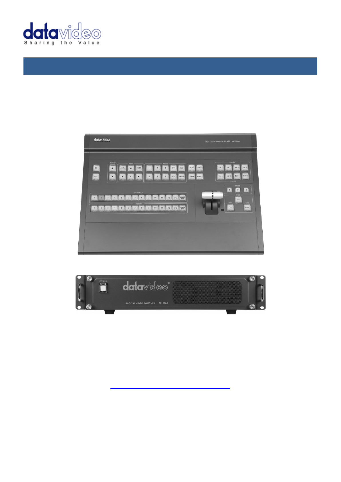
Product Overview
The SE-2800 is a cos t effective HD/SD switcher featuring eight* o r twelve channels. Thanks to a 2RU 19” form
factor and 12V DC input the SE-2800 is ideal for use in port able rack units or outside broadcas t vehicles. The SE2800 produces superb 10 bit 4:2:2 broadcast quality pictures while also offering flexible input and output
configurations. The SE-2800 also has powerful, easy to use effects, such as dual picture in picture (PIP),
downstream keyers (DSK) and logo insertion, as well as a clock and multiple still image frame stores.
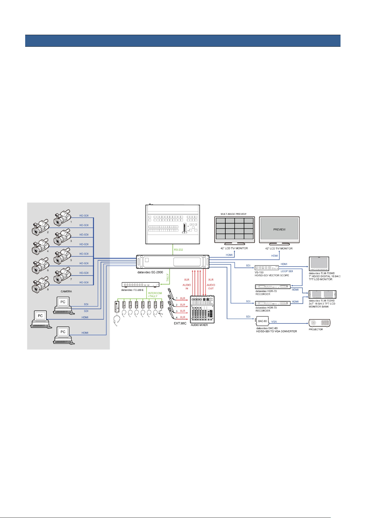
The SE-2800 has been d esigned for live pr oductions suc h as concerts, conf erence, sports and worship events as
well as news and s tudio based programm es that may need to com bine a number of video sourc es with a mixed
audio feed. The unit can also be configured and controlled over an Ethernet network allowing even greater
flexibility and even more user set up options.
That’s Datavideo, sharing the value!
*Eight channel units can be upgraded to twelve at a later date
Please speak with your dealer for more information.
6
Page 7

Features
The twelve input version can be configured as:
Twelve SDI or HD-SDI inputs,
Or Nine SDI or HD-SDI inputs with three HDMI inputs,
Or Six composite inputs, with three SDI inputs and three H DMI inp uts
Or Six composite inputs, with six SDI inputs.
The eight input version* can be configured as:
Eight SDI or HD-SDI inputs,
Or Six SDI or HD-SDI in puts with tw o HDMI inp uts ,
Or Four composite inputs, with two SDI inputs and two HDMI inputs
Or Four composite inputs, with four SDI inputs.
HDMI based single or dual screen multi-view outputs.
A choice from five set ups, two with optional HDMI Program output.
• Three user defined SDI or HD-SDI outp uts .
Each of these outputs has the option to be:
Program output
Or Preview output
Or Program output without logo
Or Program output without logo and DSK overlay
Or Aux output of a selected video input channel (single Aux).
• User defined and positioned dual picture in picture (PIP).
• Easy two step PIP source assignment using keyboard.
• Two downstream keyers (DSK) with a set up choice of basic Luma key or alpha channel.
• Easy two step DSK source assignment using keyboard.
• User choice from seven stored logos for insertion on preview and program outputs.
• One dynamic logo or moving image sequence. File type can be TGA, GIF or AVI up to 75 frames long.
• Frame Store (FS) source for each input channel. User can quick ly to ggle between a pre-loade d still image
and the connected live source.
• On screen real-time clock featuring HH:MM only – User defined position.
• User defined countdown timer for each input shown within the HDMI Multi-view output.
• Six user defined wipe butt o ns - choice of 16 wipes with optional border.
• User can define three speed buttons (in frames) for selected transition when using Auto Take button.
• T-Bar can be operated in one way or two way mode.
• Choice of 8 full raster colour backgrounds or SMPTE 75% bars for BG button.
• Up to four channels of audio can be embedded on to the SDI a nd HDMI Program outputs. Eit her from an
external audio mixer (not supplied) or selected HDMI, SDI and analogue XLR inputs.
• Audio peak meters displayed on HDMI Multi-view gives confidence of incoming and outgoing audio.
• User choice for synch input and loop through – composite black & burst or HD Tri-Level sync.
• SE-2800 can be configured over an Ethernet network using a supplied Windows 7 PC application.
• SE-2800 can be controlled remotely over an Ethernet network using a supplied Windows 7 PC application.
• Low voltage B i-colour Tally output on a sing le 25pin D-sub connector – compatible with other Dat avideo
equipment or bespoke applications.
• GPI - Externally trigger transitions or devices using the 3.5mm jack socket.
• XLR 12V DC input – Makes the unit ideal for studio or OB van based applications.
7
Page 8
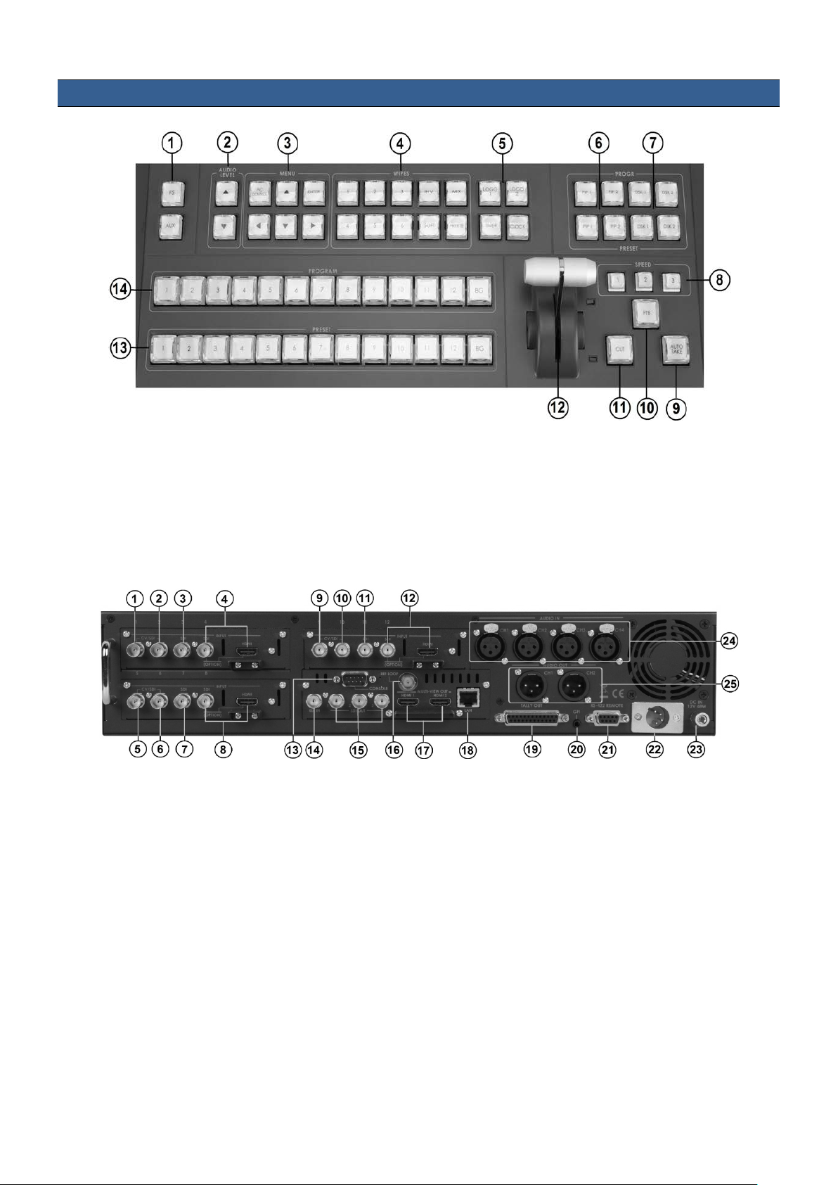
Control Panel Overview
1. Frame Store button
8. Speed Selection
2. Audio Level buttons
9. AUTO TAKE
3. PC / Menu control
10. FTB – Fade To Black
4. Transition selection
11. CUT
5. Logos 1 & 2, Clock & Timer
12. T-Bar – Manual Transitions
6. PIP selection PST & PGM
13. Preset Row (PST)
7. DSK selection PST & PGM
14. Program Row (PGM)
1. Input 1 – SD / HD-SDI / CVBS
13. Connect the SE-2800 keyboard here
2. Input 2 – SD / HD-SDI / CVBS
14. External Sync Input
3. Input 3 – SD / HD-SDI
15. User Defined SDI Outputs 1~3
4. Input 4 – SD / HD-SDI / HDMI
16. Sync Output / Ref Loop
5. Input 5 – SD / HD-SDI / CVBS
17. User Defined Multi view Outputs
6. Input 6 – SD / HD-SDI / CVBS
18. Ethernet port for PC control & updates
7. Input 7 – SD / HD-SDI
19. Tally Output connector
8. Input 8 – SD / HD-SDI / HDMI
20. GPI connector
**
9. Input 9 – SD / HD-SDI / CVBS
21. RS-422 connector (not currently used)
**
10. Input10 – SD / HD-SDI / CVBS
22. 4pin XLR Power Input connector
**
11. Input11 – SD / HD-SDI
23. Grounding Terminal
**
12. Input12 – SD / HD-SDI / HDMI
24. 3pin XLR Audio Inputs
25. 3pin XLR Audio Outputs
Connections & Controls
Main Unit - Rear Panel
** Please note inputs 9 to 12 are not present if you have purchased the eight channel SE-2800.
Eight channel units can be upgraded to twelve inputs, please talk with your local dealer.
8
Page 9
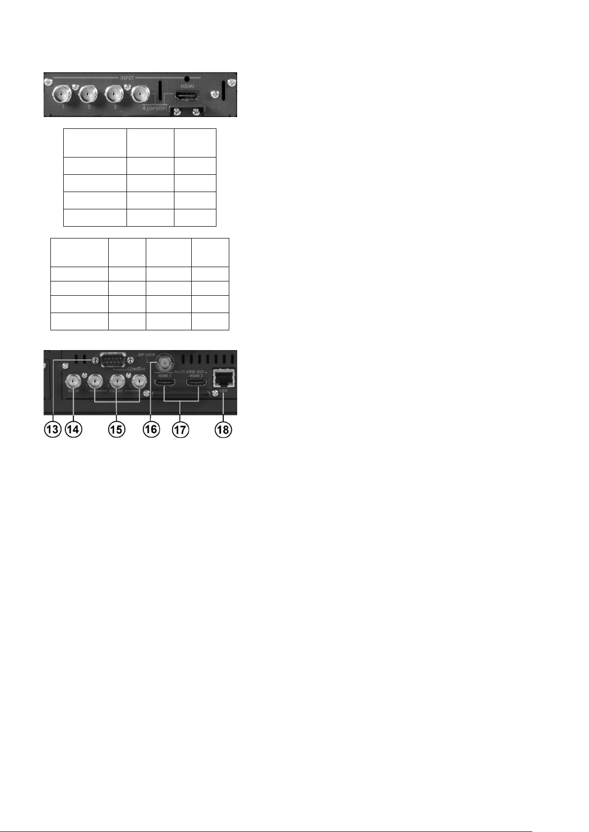
Rear Panel Connections
1, 5 & 9
Yes
Yes
---
2, 6 & 10
Yes
Yes
---
Video Input Modules
Each Video Input Module (shown top left) has the same
2800 switcher. For example, only input
This switcher cannot accept 1080P or 1280x720P or
SYNC I/O
user defined SDI
1920x1080i
HD Inputs
1, 5 & 9 Yes ---
2, 6 & 10 Yes ---
HD-SDI
BNC
HDMI
The SE-2800 can be supplied with eight or twelve video input
channels.
An SE-2800 with eight input cha nnels has two video input modules
fitted. An SE-2800 with t welve input channels has three video inpu t
modules fitted. An eight channel unit can be upgraded to twelve
inputs by adding another Video Input Module.
There are four video input channels on each Video Input Module.
3, 7 & 11 Yes --4, 8 & 12 Yes Yes
SD Inputs
3, 7 & 11 --- Yes --4, 8 & 12 --- Yes Yes
CVBS
BNC
connections, four BNC con nectors and one HDMI port. The fourth
BNC connector and the HD MI port are an option for the same input
SDI
BNC
HDMI
channel.
The two tables, on the lef t, show which types of v ideo inputs can be
connected to the SEchannels 4, 8 and 12 have the HDMI input option.
NOTE:
1440x1080i inputs and has no computer input scaling options.
To change the video standard see page 41.
The SE-2800 can be synchronised with other studio equipment
such as cameras and House sync. Input BNC (14) will accept
House sync or Tri-level syn c. Output BNC (16) can be used to pass
the sync signal to other studio equipment such as cameras or
recorders.
CONSOLE
This 9pin D-Sub connector (13) is used to connect the Control
Panel / Keyboard to the rear of the SE-2800 Main Processing unit.
HDMI MULTIVIEW OUT
The SE-2800 has two HDMI outputs (17) which can be used to
display a preset combination of inputs plus program and preset.
See page 11 for the five preset multi-vie w options .
SDI VIDEO OUTPUTS
The three BNC output connectors (15) are
outputs. Each of these SDI outputs has the option to be:
1. Program output
2. Preview output
3. Program output without logo
4. Program output without logo and DSK
5. Aux output of a selected input channel
SDI outputs 2 and 3 also have the option to be a Program output
which has been downscaled from HD to SD resolution.
ETHERNET PORT
This RJ45 Ethernet port (18) is used to connect the SE-2800 to a
PC for remote control, or to update the unit’s firmware, or to
configure the switcher. See page 25 for more details.
9
Page 10
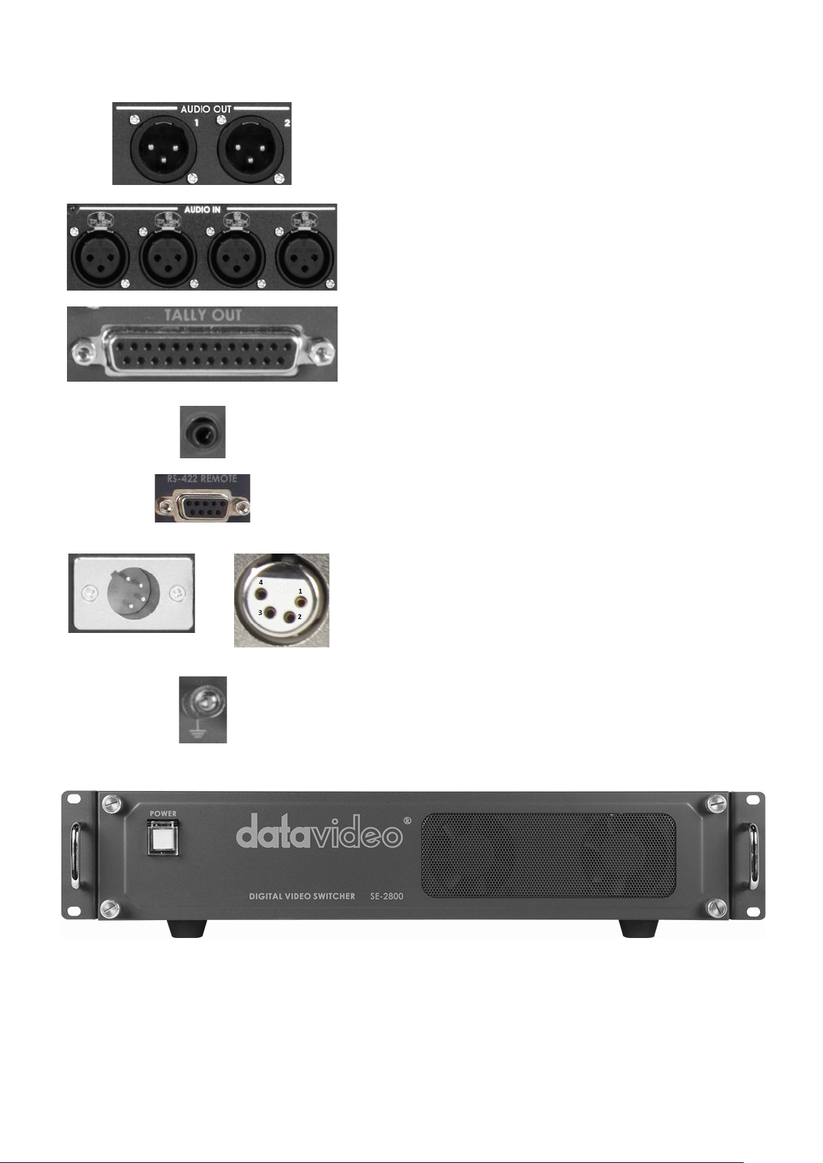
TALLY OUT
GPI
RS-422 REMOTE
DC IN
Grounding Terminal
to use wire with a cross-sectional area of at least 1.0 mm.
AUDIO OUT
Supports two channels XLR Balanced Audio output.
See page 31 for more details.
AUDIO IN
Supports four channels XLR Balanced Audio Input.
See page 31 for more details.
The SE-2800 T ally Out put port pro vides bi-colour tally inform ation
to a number of other Datavideo products, such as the ITC-100
eight channel talkback system or the Datavideo TLM range of
monitors. See page 36 for more details.
The GPI socket can be used for simple external control.
See page 35 for more details.
This feature is not currently active. A firmware update may be
released at a later date. P lease check with your local Datavid eo
office for advice on this connection and the latest firmware.
Connect the supplied 12V 5A PSU to this 4pin XLR socket.
Pin 1 = GND ( - )
Pin 2 = NC
Pin 3 = NC
Pin 4 = VCC ( + )
Main Unit – Front Panel
The front panel on th e SE-2800 main unit has a gril le for two airflo w cool ing f ans. Pleas e do not bl ock or c over this
grille as the unit m ay overheat. This grille sh ould also be kept free of dus t. The front panel can be removed by
using the four thumbs c rews. A s of t br ush or c loth can then be us ed to c l ean th e grille before attaching it b ac k to the
unit.
The power button starts and shuts down both the SE-2800 main unit and its attached keyboard.
When connecting this unit to any other component, make sure
that it is properly grounded by connecting this terminal to an
appropriate point. W hen connecting, use the sock et and be sure
10
Page 11
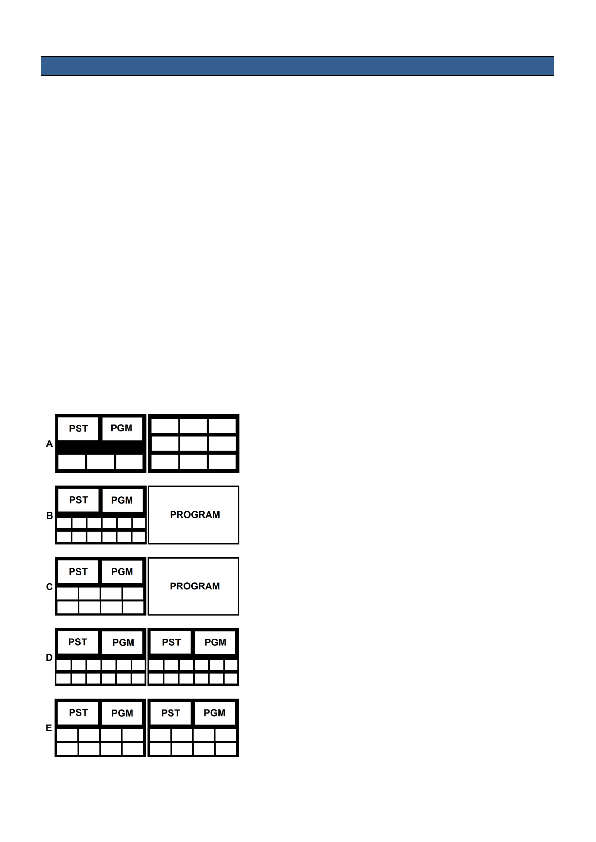
HDMI Multi-view
HDMI 1 HDMI 2
Shown left are the five multi-view configuration options A to E.
SE-2800 Multi-view m onitoring is avai lable across one or two HDMI monitors (not supplied). These HDMI output s
can be used to monitor video and audio in a num ber of dif ferent configurat ions. For each s et up, em bedded audio
level indication is also available on all inputs as well as the Preview and Program windows.
This Multi-view is supp lied from the HDMI connection(s ) on the rear panel. (See page 8, Rear Panel, item 17.)
When connected to two compatible HDMI monitors a variety of multi-image layouts is possible.
Configuration A:
- On HDMI screen 1: 9 live inputs
- On HDMI screen 2: 3 live inputs with additional Preview and Program windows
Configuration B:
- On HDMI screen 1: 12 live inputs with additional Preview and Program windows
- On HDMI screen 2: Program window
Configuration C:
- On HDMI screen 1: 8 live inputs with additional Preview and Program windows
- On HDMI screen 2: Program window
Configuration D:
- On HDMI screen 1: 12 live inputs with additional Preview and Program windows
- On HDMI screen 2: Same as HDMI screen 1
Configuration E:
- On HDMI screen 1: 8 live inputs with additional Preview and Program windows
- On HDMI screen 2: Same as HDMI screen 1
How t o change the Multi-view output
To change the multi-view optio n on your switcher pres s the ENTER
button in the MENU ar ea of the SE-280 0 Contro l Panel / Keyboard.
This will display an on screen m enu on HDMI output 1. Then use
the arrow down button to highlight the option M ulti Screen Mode.
Use the arrow keys to highlight your preferred option from
those shown on the lef t. Use the arrow keys to place a tick in the
selection box and then press ENTER to save this choice.
On screen Tally indication
The SE-2800 Multi-Image Preview supplies basic tally information
by highlighting the live Pro gram input source with a red border, and
the cued next input source with a yellow border.
Function Area
Below the Program and Preset image windows is a function area
occupied by a real time Clock , Countdown T imer (if active), chosen
Wipe indicator, PC or Console contr ol indication and chosen Audio
mix and Audio level indicators.
Labels
Below each video input channel window there is a label. These
labels can be edited using the software supplied with the SE-2800,
see page 25 for more details.
11
Page 12
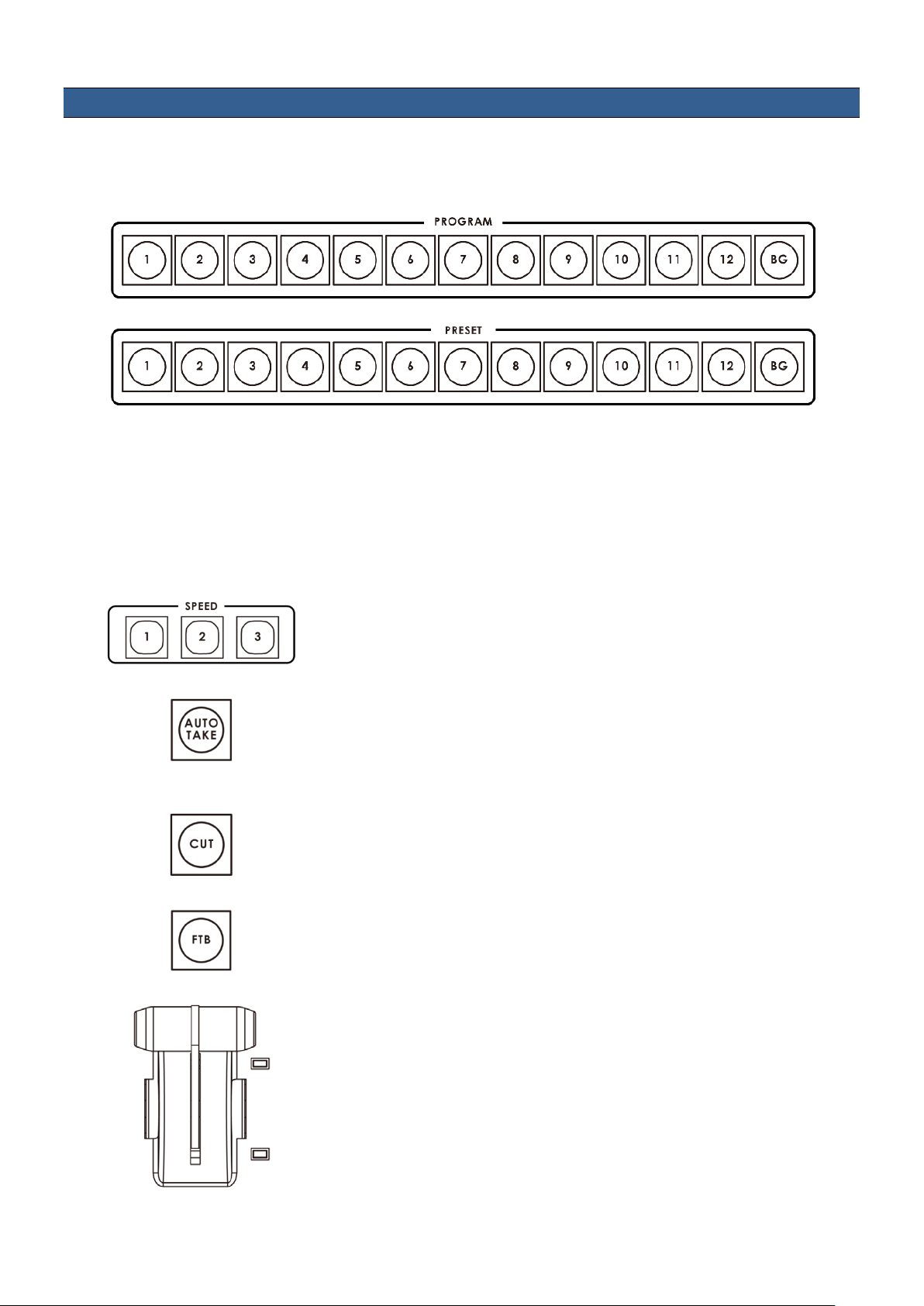
Keyboard Controls – Video Switching
SPEED
AUTO TAKE
CUT
FTB
T-Bar
Program and Preset rows
The Program row of buttons is the active channel, this is the live output. The active channel will appear as the
Program Output (PGM). You c an swit ch or CUT from one video source to another direc tly on the Program row. You
will see the multi view PGM output change as you press different keys along this top row of buttons.
The Preset row is the cued channel, this channel will appear in the PST or Preview window. The Preset row
selection decides which input will be transitioned next when using any of the transition controls.
N.B. The keys on the Program and Pre set rows will be inactive while the T-Bar is active o r moving. Only
when the T-Bar is fully up or fully down will the keys respond.
BG
Background button – assigns a background colour or SMPTE 75% bars for use on the Program and Preset row.
There are three speed buttons which can be defined by the user. By
pressing a speed button th e user is choos ing the rate of tr ansition or tim e
taken when using the AUTO TAKE button.
This performs an automated switch from the current program source to
the selected preset source. The selected transition wipe or dissolve will
also be used. The timing of the transition is set by the chosen Speed
button.
This performs a simple immediate switch from the current main source to
the selected sub source. The selected transition wipe or dissolve is not
used.
Fade To Black, this button fades the current video program source to
black. When press ed again it acts in r everse from com plete black to the
currently selected program video source.
This performs a m anually controlled transition from the current pr ogram
source to the selected preset source. The selected transition wipe or
dissolve will be used . When the T-Bar has tra vell ed a s f ar as it c an go t he
transition between sourc es is complete. The T -Bar has indicators next to
it which light when the transitio n is com plete.
The T-Bar can be operated in one of two modes which is chosen by a
menu option, see pag e 17 onwards for more details.
12
Page 13
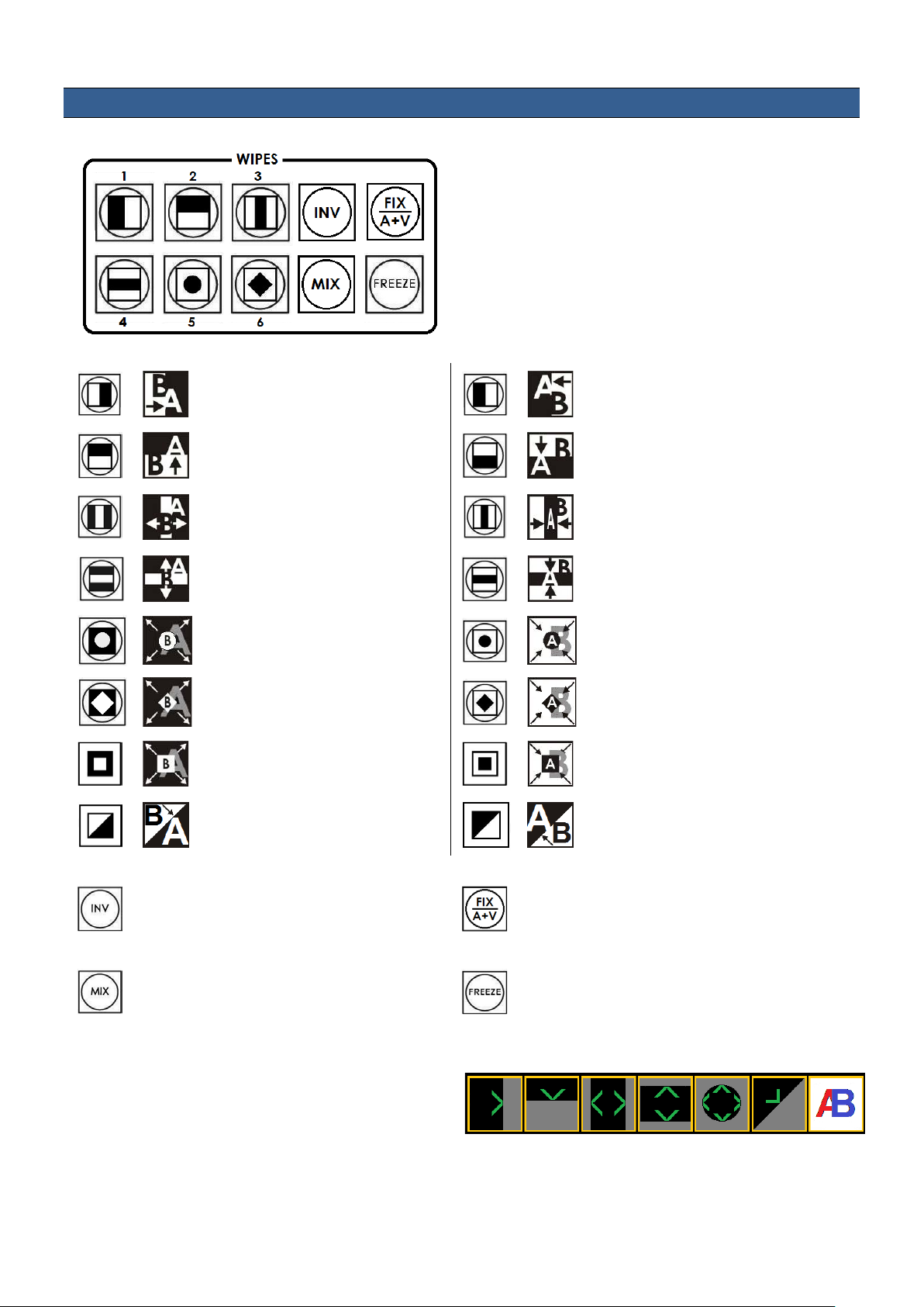
Keyboard Controls – Video Trans itions
The SE-2800 features six user defined wipe buttons, an
buttons.
INV
opposite direction.
FIX / A+V
Audio Fixed and Audio-F-Video (A+V).
MIX
Dissolve for the next transition.
FREEZE
live video of the selected program source.
Transition Confirmat ion
Transition Selection
A/B dissolve or MIX button, an INV or Invert wipes b utton
and a FREEZE button.
All wipes can have a n optional col our border app lied. The
wipe border width a nd colour are chosen within the menu
system.
Transitions can be p erformed m anually us ing the T -Bar or
automatically by using the SPEED and AUTO TAKE
Vertical Wipe Left to Right.
Horizontal Wipe Bottom to Top.
Vertical Wipes from Centre to Left
and Right sides.
Horizontal Wipes from Centre to
Top and Bottom.
Circle Wipe from Centre to
outside edges.
Diamond Wipe from Centre to
outside edges.
Box Wipe from Centre to outside
edges.
Diagonal wipe from upper left to
lower right.
Vertical Wipe Right to Left.
Horizontal Wipe Top to Bottom.
Vertical Wipes from Left and Right
sides to Centre.
Horizontal Wipes from Top and Bottom
to Centre.
Circle Wipe from outside edges to
Centre.
Diamond Wipe from outside edges to
Centre.
Box Wipe from outside edges to
Centre.
Diagonal wipe from lower right to
upper left.
Invert the selected wipe so it travels in the
Pressing this button selects a basic A/B
The selected transition is highlighted in the status
area of the HDMI multi-view output. When the INV
button is pressed the six wipe icons change to t heir
opposite direction icon.
Switch the audio mixing selection between
Freeze the program source image or return to
13
Page 14

Keyboard Controls – LOGO 1, LOGO 2, CLOCK a nd TIMER
The SE-2800 has the ability to s tore six stat ic logos a nd one d ynamic logo. The
logo files are trans ferred to the SE-2800 from a W indows PC us ing the E thernet
connection and the supplie d SEConfig software. See page 25 for mor e details
on using this software.
LOGO 1
The LOGO 1 and LOGO 2 buttons are use d to dis pla y pre-selected logos on th e
SE-2800 Preset and Program outputs. W hen the button is active the selected
logo is shown. These logos are selected from the switcher’s memory and
positioned using a menu option see page 17 for details.
LOGO 2 or CLOCK
The user cannot display LOGO 2 and CLOCK at the same time. Instead use
LOGO 1 and CLOCK together or use LOGO 1 and LOGO 2 together.
The clock time can be synchronised with a computer or set manually using a
menu option. The colo ur and font used in the clock digits can be cha nged using
the supplied SEConfig software. See page 25 for more details on using this
software or see page 17 onwards for the Clock menu options.
TIMER
In some mixing or switching applications it is useful to have a countdown timer. It
could be that the input is a pre-recorded vi deo clip and you need t o know when
to be ready to switch away from it.
This countdown tim er function is onl y seen in the status ar ea of the HDMI multiview output to the right of the nor mal Clock function. T he timer can be selected
for one input channel, several channels or all channels.
When the TIMER button is active and the user switches to a selected input
channel the countdown starts on the HDMI multi-view.
The value of the count down, in m inutes and seconds (MM: SS), is s et b y a m enu
option. Whilst the countdown is in progress T-Bar operation is ignored.
When the countdown reaches zero the user can then switch or transition to
another input channel. If the countdown reaches zero the switcher will not
automatically change to the selected Preset source.
14
Page 15

Keyboard Controls – PIP1, PIP2 , DSK1 and DS K2
PIP Preset and PIP Program
DSK Preset and DSK Program
When looking at the top right c orner of the SE-2800 Control Pa nel / Keyboard
there are four PIP keys. These are labelled Program and Preset. The upper
PIP1 and PIP2 keys relate to activating Picture In Picture images on the
Program outputs. T he lower PIP1 and PIP2 k eys relate to activat ing Picture In
Picture images on the Multi-view or Preview outputs.
Assigning a video source input to a PIP
Using the lower PIP1 or PIP2 but tons you can assign a selected v ideo input to
the chosen PIP video layer.
1) First press and hold down the requ ired PIP button on the lower row. T he
Preset row of input sources will light.
2) While still holding down the PIP button , press to select the required input
from the Preset row.
3) The input will flash to confirm it is selected.
This selection will a lso be confirmed on the HDMI Multi-view, with a P1 or P 2
label shown next to the selected input image.
The full PIP process is described on page 22.
When looking at the top right c orner of the SE-2800 Control Panel / Ke yboard
there are four DSK keys. These are labelled Program and Preset. The upper
DSK1 and DSK2 ke ys relate to act ivating D own Strea m Keying on the Progr am
outputs. The lower DSK1 and DSK2 keys relate to activating Down Stream
Keying on the Multi-view or Preview outputs.
Assigning an input to a DSK channel f or keying
Using the lower DSK1 or DSK2 buttons you can assign a selected video input to
the chosen DSK video layer.
1. First press and hold down the required D SK button on the l ower row. The
2. While still holding down th e DSK button, press to selec t the required input
3. The input will flash to confirm it is selected.
This selection will als o be confirmed on the HDMI Multi-vi ew, with a T1 or T2
label shown next to the selected input image.
The full DSK process is described on pag e 23.
Preset row of input sources will light.
from the Preset row.
15
Page 16

Keyboard Controls – Frame Store , AUX and Audio level
FS – Frame Store Button
AUX Source Selection
Audio Level
The SE-2800 has eight or twelve v ideo channels, depending on the num ber of
inputs it has. Each of these channels has its own F ram e Stor e , making a total of
eight or twelve Frame Stores. Each of these Frame Stores can hold one still
image. This still image can be called i nto the productio n by using the FS button
located at the top left c orner of the SE-2800 C ontrol Panel / Ke yboard. The FS
button allows the user to toggle between the s till image of the Fram e Store or
the live video input also connected to that same video channel.
How to choose live video input or Fram e S t ore
1. First press and hold do wn the FS button. The Pres et row of input sour ces
will light.
2. While still holding down the FS button, press the required input on the
Preset row.
3. The input button will flash to confirm the Frame Store is selected.
This selection will a lso be confirmed on t he HDMI Multi-vie w, with the selected
channel showing the live input or frame store image.
The contents of eac h Frame Store is uploaded to th e SE-2800 from a PC. The
supplied SEConfig software is used to do this. The file upload process is
described on page 25.
The SE-2800 has three user defined SDI outputs , s ee page 9 it em 15. One or all
of these outputs can be se t up as an auxiliary (AUX) output via a m enu option.
See page 17 onwards for details.
The AUX output source can be quickly selected in the following way.
1. First press and hold do wn the AUX button. The Pr eset row of input sources
will light.
2. While still holding down the AUX button, press the required input on the
Preset row.
3. The input button will flash to confirm the AUX source is selected.
This selection will also be confirmed by the SD/HD-SDI Monitor supplied with
these AUX images.
The SE-2800 has ab ility to do a basic mix/s witch of analogue, SD I and HDMI
embedded audio, see page 31 for details.
The AUDIO LEVEL b uttons are r elated t o the le vel of t he Program audio outp ut,
whether SDI embedded or analogue XLR.
16
Page 17

Menu Options
HDMI SD 16:9
When the ENTER button is pressed the Main Menu l ist is displayed on the HDMI 1
Multi-view output.
This section covers the Menu options in the order that they appear on the
SE-2800 HDMI 1 Multi-view. These settings may also appear in more detail
elsewhere in this instruc tio n m anual. Options ma y vary dependi ng on th e fir m ware
version in use.
Once the chosen setting has been conf irmed with the ENTER button it is stored within the switchers non-volatile
memory.
Version Number
V.xx.xx - where xx.xx is the firmware version number
Input Video Settings
Inputs Standard and Format
Brightness
Contrast
Saturation
Aperture
Y-C Delay
Set To Nominal
Inputs 1,2,5,6,9 &10 Can be a choice of HD SDI*
SD SDI 4:3
SD SDI 16:9
CVBS 4:3
CVBS 16:9
Inputs 3,7 &11 Can be a choice of HD SDI*
SD SDI 4:3
SD SDI 16:9
Inputs 4,8 &12 Can be a choice of HD SDI*
SD SDI 4:3
SD SDI 16:9
or
HDMI*
HDMI SD 4:3
Range xx to xx
Range xx to xx
Range xx to xx
Not used in current firmware
Not used in current firmware
Reset to default values
*All HD inputs are natively 16:9 as pect .
Input Audio Settings
SDI Embedded Audio Set. Inputs 1 to 12
HDMI in Embedded Audio Pair Input 4,8 or 12
Outputs Emb Audio Group Outputs 1,2 or 3
Auto Audio Mixing Type
Level
Nominal
User choice of
Range -60 to +60
Resets value to zero
User choice of
User choice of
User choice of
X type or V type
Tick selection
17
Group 1,2,3 or 4
Pair 1 or 2
Group 1,2,3 or 4
Group 1,2,3 or 4
X type = A/B cross fade
V type = Fade out A then Fade in B
Page 18

T-Bar Audio Mixing Type
Tick selection of
Follow auto audio mixing type (use above option)
By the end (clean cut or immediate audio switch)
PIP Settings
LOGO Settings
Speed Buttons Setting
Position PIP1
Size PIP1
Border PIP1
Position PIP2
Size PIP2
Border PIP2
Logo1
Logo2
Speed1
Speed2
Speed3
X-Position (Left to right) = 000 to 097
Y-Position (Lower to Upper) = 000 to 108
PIP Size = 1 (small) to 33 (large)
Border Size = 0 (OFF), 1 (Thin) to 15 (Thick)
Border Color = 1 to 8 (user defined colours)
1=White, 2=Yellow, 3=Cyan, 4=Green, 5=Magenta,
6=Red, 7=Blue, 8=Black
X-Position (Left to right) = 000 to 110
Y-Position (Lower to Upper) = 000 to 135
Selection = 1 to 8
Logo selection 1 to 7 are still image
Logo 8 selection is dynamic moving image
Range 1 to 127 (Frames)
Wipe 1 to 8 (See page 13 also)
Soft Edge 0 to 4
Wipe Buttons Setting Buttons 1 to 6
OUT 1 is an HD SDI only user choice of Program
Program Logo Free
Program Logo & Titles Free
Preview
Aux
OUT 2 user choice of Standard & Format HD SDI
Outputs Mode
DSK Settings
SD SDI 4:3
SD SDI 16:9
Plus MODE choice of Program
Program Logo Free
Program Logo & Titles Free
Preview
Aux
OUT 3 has the same user choices as OUT 2
Titles 1
Titles 2
Color 1 to 8
1=White, 2=Yellow, 3=Cyan, 4=Green, 5=Magenta,
6=Red, 7=Blue, 8=Black
Titles + a-CH mode (alpha channel)
Luma Key mode
Luma Key Level 0 (black) to 255 (white)
18
Page 19

BG Color Setting
User choice of background colour from 1 to 9
1=White, 2=Yellow, 3=Cyan, 4=Green, 5=Magenta, 6=Red, 7=Blue, 8=Black,
9 = SMPTE 75% colour bars
T-Bar Mode
1kHz to Bars
Keys Brightness
Keys Mode
Audio Level is shown
Reference
One Way Mode
Two Way Mode
When BG Color Setting option above = 9
1kHz tone can be ON or OFF depending on tick selection
User choice of 1 to 4
Brightness of keyboard buttons, 1= Low, 4= High
Tick selection ON or OFF, ON=Active buttons are Red, OFF=Green is Active
Tick selection ON or OFF, ON=Audio Peak Meters shown on HDMI Multi-view
External Tick selection for ON or OFF
Mode Choice of HD Analog 3 Level Signal
Or SD Composite PAL/NTSC
H-Timing Zero to 15
= T-Bar operates transition in only one direction
= T-Bar operates transition in both directions
Aux
Factory Settings
Clock Settings
Multi Screen Mode
GPI Settings
The value shown here relates to the selected input – See page 16 also.
This setting is also related to the Outputs Mode on page 17.
Tick selection ON or OFF, ON= Reset all settings to their default values.
X-Position (Left to right) = 000 to 110
Y-Position (Lower to Upper) = 000 to 135
Set Hours
Set Minutes
Clear Seconds
This selection relates to the HDMI outputs 1 (=W1) and 2 (=W2).
A : W1 = PGM + PVW + 3 IN ; W2 = 9 IN
B : W1 = PGM + PVW + 12 IN ; W2 = PGM
C : W1 = PGM + PVW + 8 IN ; W2 = PGM
D : W1 = PGM + PVW + 12 IN ; W2 = W1
E : W1 = PGM + PVW + 8 IN ; W2 = W1
See page 11 also.
Input Select = Chosen input number
Time Delay = In frames between 1 to 75
19
Page 20

Countdown Timer Settings
Input channels 1-12, Va lue 1 -12
more details )
Each input can selected for Count Down ON or OFF.
If Count Down is ON then the Down Counter value is set in minutes and
seconds (MM:SS) - Max.= 1 Hour or 60:00, Default = 15 Seconds or 00:15
Audio Associations
Multi Screen Audio
( used to choose an embedded audio source – see page 31 onwards for
Tick selection of Program or Preview audio on the HDMI outputs.
20
Page 21

SE-2800 Video Layers
The SE-2800 is a Standard Definiti on or High Definition Digital Video S witcher and as well as mixing video and
audio sources it has additional functions such as Picture In Picture (PIP), DSK LUMA KEY and LOGOs.
Before attempting to use the SE-28 00’s PIP, DSK LU MA KEY and LOGO func tions it may help to first unders tand
the order of the video layers at the SE-2800 Program (PGM) outputs.
The Background video layer is the normal video la yer when mixing and switc hing with the SE-280 0. It occupies
the whole screen area of the Program output. T his la yer can be hidden or part h idden b y the PIP, DSK a nd LOGO
layers in front of it.
The PIP 1 layer does not occupy the whole screen and is shown in front of the Background video layer when
enabled. In som e setups the PIP 1 im age can be hidden behind the PIP 2 im age. This is not a fault. Change t he
position or size of the PIP 1 or PIP 2 image if required.
The PIP 2 layer does not occ upy the who le scr een and is s hown in f ront of the Bac kgr ound video and P IP 1 la yers
when enabled. In som e setups the PIP 1 im age c an hide the PIP 2 im age. Change the positi on or si ze of the PIP 2
or PIP 1 image if required.
The DSK 1 layer can occupy the whole s creen. If set up incorrectl y this layer can stop the video layers behind it
from being seen properl y. Re-adjus t your D SK 1 setti ngs or s witch off the DSK1 f unction on th e SE-280 0 to res tore
the video behind it.
The DSK 2 layer can occupy the whole s creen. If set up incorrectl y this layer can stop the video layers behind it
from being seen properl y. Re-adjus t your D SK 2 setti ngs or s witch off the DSK1 f unction on th e SE-280 0 to res tore
the video behind it.
The LOGO and Clock layer does not occupy the whole sc reen and all other la yers are visible thro ugh it. A logo if
positioned incorrectl y can p artia lly hide an important part of the video, PIP or CG LU M A KEY layers. Typically logos
or station ID bugs are placed in a corner of the screen.
NB: Wher e possible prepar e and posit ion the upper video la yer elem ents in advanc e of the live pr oduction s tarting
to avoid them appearing on the program output incorrectly.
Most broadcast net works have gu idelines and advice on the us e of video, im ages, m us ic, logos and on s cre en text
so it is best to chec k beforehand when planning a p roduction. Do not use copyright protected content until you
have the relevant perm issions. Information on royalty f ree video, images and music is widel y available, speak to
your local dealer or search for advice on the internet.
21
Page 22

PIP – Picture In Picture function
PIP Preset and PIP Program
The SE-2800 Picture in Pict ure functi on allows you to place on e or two smaller PI P images over a c hosen f ull size
background image. T he smaller PIP im ages c an be set to pre-def ined si zes and pos itioned alm os t anywher e within
the Preview/Program screen area. These PIP windows can also have a coloured border applied, and can be
brought into the production with a default PIP dissolve transition.
PIP Settings
Before trying to activate t he PIP function it is b est to understand how to set up or choos e the rig ht options for your
production. Press the ENTER Key in the MENU area of the SE-2800 keyboard. Navigate to the PIP Settings
option using the down arrow key. The PIP menu options provided here are:
PIP Settings Position PIP1
Size PIP1
Border PIP1
Position PIP2
Size PIP2
Border PIP2
X-Position (Left to right) = 000 to 097
Y-Position (Lower to Upper) = 000 to 108
PIP Size = 1 (small) to 33 (large)
Border Size = 0 (OFF), 1 (Thin) to 15 (Thick)
Border Color = 1 to 8 (user defined colours)
1=Yellow, 2=Cyan, 3=Green, 4=Magenta, 5=Red, 6=Blue
When looking at the top right c orner of the SE-2800 Control Pa nel / Keyboard
there are four PIP keys. These are labelled Program and Preset.
The upper PIP1 and PIP2 k eys relate to activating Pict ure In Picture im ages on
the Program outputs.
The lower PIP1 and PIP2 ke ys relate to activating Pict ure In Picture images on
the Multi-view or Preview outputs.
Assigning a video source input to a PIP
Using the lower PIP1 or PIP2 but tons you can assign a selected v ideo input to
the chosen PIP video layer.
1) First press and hold down the requ ired PIP button on the lower row. T he
Preset row of input sources will light.
2) While still holding do wn the PIP button, press to selec t the required input
from the Preset row.
3) The input will flash to confirm it is selected.
This selection will a lso be confirmed on the HDMI Multi-view, with a P1 or P 2
label shown next to the selected input image.
22
Page 23

DSK function (CG / LUMA KEY)
DSK Preset and DSK Program
The SE-2800 has two Down Stream Keyers (DSK1, DSK2). This means it is able to take a key source video input
and replace the white or black parts of this image with the video from another source. If the input video carries an
alpha channel it is also possible to key in this way too.
DSK Settings
Before trying to activate t he DSK f unction it is bes t to unders tand ho w to set up or c hoose the ri ght opti ons f or your
production well in advance of the production.
Press the ENTER Key in the MENU area of the S E-28 00 keyboard. Navigate to the DSK Settings option using the
down arrow key. The DSK menu options provided here are:
DSK Settings Titles 1 (DSK1)
Titles 2 (DSK2)
When looking at the top right c orner of the SE-2800 Control Pa nel / Keyboard
there are four DSK keys. These are labelled Program and Preset.
The upper DSK1 and DSK2 k eys relate to activating Down Stream Keying on
the Program outputs.
The lower DSK1 and DSK 2 keys relate to activating Down Stream Ke ying on
the Multi-view or Preview outputs.
Assigning an input to a DSK channel f or keying
Using the lower DSK1 or DSK2 buttons you can assign a selected video input to
the chosen DSK video layer.
1. First press and hold down the required D SK button on the l ower row. The
2. While still holding down th e DSK button, press to selec t the required input
3. The input will flash to confirm it is selected.
This selection will als o be confirmed on the HDMI Multi-vi ew, with a T1 or T2
label shown next to the selected input image.
Titles + a-CH mode (alpha channel mode)
Luma Key mode
Luma Key Level 0 (black) to 255 (white)
Preset row of input sources will light.
from the Preset row.
23
Page 24

Example SE-2800 and CG-350 Set Up
An example set up for the DSK1 and DSK2 feature would be to sup pl y separate HD-SDI Key and Fill sign als fr om
a Datavideo CG-350 Character Generator PC. This PC can provide CG overlays of text and graphics fr om the
outputs of a 3
1. Ensure the CG-350 software is set up for External key in its settings.
2. The Key sig nal from the Deck link card is then fed to input 9 on the SE-2800 (see diagram below). Press and
hold down the DSK1 butt on on the lower row. The Preset row of input sources will light, choose input 9. T he
input will flash to confirm it is selected. This selection will also be conf irmed on the HDMI Mu lti-view, with a T 1
shown next to the selected input image.
3. The Fill signal from the Decklink card is then fed to input 10 on the SE-2800 (see diagram below).
4. Now go into the m ulti-view m enu by pressing ENTER on the SE-2800 k eyboard. Naviga te to DSK SETTI NGS
> TITLES 1 and choose T ITLES + a-CH MODE. T he SE-2800 will autom atically use inputs 9 and 10 as ke y
and fill.
If you have two CG-350 computers then the same steps can be used for DSK2 set up but using inputs 11, 12 and
the second CG-350 PC.
If you have an SE-2800 wit h on l y eight i npu t c han nels , then you could set up a sin gle k e y and f il l DSK, us i ng i nputs
5 and 6. This leaves six other video input channels to work with.
If you have an SE-2800 with onl y eight input cha nnels and need to us e two DSKs then separat e Luma k ey set ups
can be created using the instructions on page 23. This leaves six other video input channels to work with.
rd
party PCIe video card such as Blackmagic Design’s D ec klink HD Extreme 3D+ card.
24
Page 25

How to obtain software or firmw ar e for the SE-2800
6. If you immediately get an error window, do not
7. Now Press PC Control bu tton so it is ON in the
8. Select Ethernet to display the Computer’s IP
down list. The first three numbers in both IP
ow. These are; switcher, settings, input
settings, multi screen window signs (source
The latest Firmware updat es and Software applicatio ns for this switcher can be obtai ned by contacting your local
Datavideo office or dealer. A list of regional Datavideo offices is provided at the rear of this manual.
Switcher configurati on us ing a computer – SEConfig software
It is possible to configure the SE-2800 with a Windows 7 computer using an Ethernet connection.
1. Switch off or shut down the SE-2800 and Computer in the normal way.
2. Connect the Ethernet cable between the SE-2800 rear panel and the Windows 7 Computer.
3. Turn on the Windows 7 Computer and SE-2800 switcher.
4. Install the supplied SEConfig software on to a Windows 7 Computer.
5. Double click the SEConfig DV icon to launch the application.
worry, click OK.
MENU area of the SE-2800 keyboard.
Address. Click the Find button to find a nd display
the SE-2800 Switcher’s IP Address in the drop
addresses should match. See below example.
9. Click Connect and additional function tabs will
become available at the top of the application
wind
labels), still pictures, logos, dynamic logo, multi
screen A, multi screen B+D and multi screen C+E
25
Page 26

Switc h er tab
This first tab can be used to choose the method of
connection between the computer and the switcher.
In this case the SE-2 800 is connecte d using selected
Ethernet IP addresses.
Note that the first three numbers in the IP a ddresses
of the switcher and computer should be the same.
The last number in each IP address should be
unique.
If you are connecting for the first time you may be
asked by the com puter to change the firewall se tting
to allow this application to connect to the switcher.
Profiles
It is possible to store the current prof ile or settings of the switc her to your com puter. This file can then be re stored
to the machine at a later date allowing simple configuratio n of the unit. Depending on the inclu ded levels of the
profile this save process may take some time to complete.
Settings tab
The settings tab is another way to change the menu
settings of the s witcher. The opt ions may appear in a
slightly different order to those in the onscreen menu
described on page 17.
Each menu option ca n be expanded by c licking on the
plus sign in the left hand pane. The right hand pane
shows any values which can be changed.
Input settings tab
The Input settings tab allows each input to be
configured from the computer.
Note due to the design of the switcher different inp uts
may have more or les s options as they are not all the
same. See page 9, Video Input Module.
Each menu option can be ex panded b y clicking on th e
plus sign in the left h and pane. The right hand pane
shows any values which can be changed.
26
Page 27

Multi screen window signs (labels) tab
This tab allows the user to rename the input source
labels on the HDMI multi view.
The READ button can be us ed to load th e curr ent labe l
of a selected input into the app lication window on the
left.
This selected label can then be edi ted using the TEXT
box. If required the f ont and colour of the text can also
be changed.
The WRITE button can then be used to write the ne w
label text into the switcher’s memory.
Still pictures (FS) tab
Each switcher has the ability to st ore still pictures in its
frame stores. If the switcher has eight inputs it has th e
ability to store eight s till pictures. Twelve pictures can
be stored if the unit has twelve inputs.
See FS button on page 16 also.
The LOAD button can used to browse for a picture
stored on the computer . T his pictur e is then loaded into
the application window.
The WRITE button can the n be used to save the new
picture into a selected frame store on the switcher.
Logos tab
The SE-2800 can store up to seven still logos in its
memory.
Using the logos tab you can use the LOAD button to
browse for a logo stored on the computer. T his logo is
then loaded into the application windo w.
The WRITE button can then be used to save the new
logo into a selected logo store on the switcher.
27
Page 28

Dynamic Logo tab
The SE-2800 can store one dynamic moving logo in
its memory. The dynam ic logo can be a targa (TGA)
sequence, GIF or AVI. It must be no longer than 75
frames/images long.
Using the Dynamic logo tab you can use the LOAD
button to browse for a logo sequence of images stored
on the computer. This logo sequence is then loaded
into the application window.
The WRITE button can then be used to s ave the new
logo sequence into the dynamic logo store on the
switcher.
Multi screen A tab
Multi screen B+D tab
Multi screen C+E tab
These three tabs are used to write ne w Mult i screen la youts to the switcher in order to change the HD MI m ulti-view
layouts as described on page 11.
NOTE: Only change these layouts wi th guid ance from your local Datav ideo off ice as attemp ting to ed it or loa d your
own layouts may result in a poor outcome or a non-responsive switcher.
28
Page 29

Setting up with the SE Remote s of tware
It is possible to control t he SE-2800 with a Windows 7 com puter using an Ethernet connection. The SE R emote
software supplied with the switcher needs to be installed on the computer first.
Connect an Ethernet cable between the PC and t he SE -2800 switcher.
Turn on the PC and SE-2800.
The SE-2800 then needs to be place d into PC Control mode. To do this pres s the PC Control button on the SE-
2800 Control Panel or keyboard.
Now you can launch the SE Remote software on the PC.
Remote software displays an image of the SE-2800’s keyboard as shown below.
SET function
The Settings or SET button is located just above the T-Bar in the SE Remote display above.
When clicked a new windo w will open as shown left. This
Settings window is used to match the software to the IP
address of the connected SE-2800 switcher.
If unknown, the switcher’s IP address may be found by
using the SEConfig software first.
NOTE: It is not possible to run both the SEConfig and SE
Remote software applications at the same time.
The Find button within the SEConfig software will help confirm the IP addr ess of the switcher. See p age 25 for
more information on SEConfig.
The PC used must be in the sam e IP network as the SE-2800. So the firs t three octets (numbers) in the PC’s IP
Address must match the first three octets of the switcher’s IP address. The fourth octet should be a different
number for the PC and switcher.
To reset the IP Address of the PC/laptop use the Network and Sharing Center option in Windows 7 Control
Panel. Click on Local Area Connection then Properties. Click to highlight Internet Protocol Version 4
(TCP/IPv4) then click Properties again. Then click Use the following IP address.
29
Page 30

Controlling the switc he r w it h a computer – SE Remote software
It is possible to control t he SE-2800 with a Windows 7 com puter using an Ethernet connection. The SE R emote
software supplied with the switcher needs to be installed on the com puter first. The SE-2800 then needs to be
placed into PC Control mode. To do this press the PC Control button on the SE-2800 Control Panel. Once
launched the Remote s oftware displ ays an im age of the SE-2800’s keyboard as s hown belo w. An y active fun ctions
or selections will be shown with a red button or key. These buttons or keys can be clicked with a mouse or
alternatively you could use a touch screen monitor. See previous page for set up information.
Software based Macro func ti ons
It is possible to record a Macro type playlist to the computer when using the SE Remote software. This Macro
function allows these pre-rec orded keyboard actions or select ions to be played back within a project wher e timing
is important or where the same steps are repeated throughout the production. The Macro function buttons are
REC, and PLAY. These buttons are located just above the T-Bar in the SE Remote display above.
REC & PLAY functions
Left mouse click the grey REC button and it will light up red. All of your actions when using the Remote Console will
now be recorded to f ile. The onl y action that will not b e recor ded is the T -Bar, us e the CUT or AUT O TAKE buttons
instead. The function buttons just above the T-Bar as listed on this page are also ignored.
Click the red REC butt on a gai n and a s ave win do w w ill app ear . You can n ow save the recorded acti ons as a m ac r o
text file to a chosen location on the computer.
Click the grey PLAY but ton and a load file window will appear. You can now browse t o and load a m acro text file.
When you load a file the recorded actions will begin to play back until the end of the file.
TIME function
This button is located just above the T-Bar in the SE Remote display above. Mouse clicking on the TIME button will
synchronize the time on the SE-2800 switcher to the current time on the computer.
30
Page 31

AUDIO function
Overview
The SE-2800 has a s imple, cost effective, aud io switcher built in. The S E-2800 has the abilit y to take audio from
several sources either X LR analogue, SDI and/or HDMI inputs . The audio can be embedded onto the H DMI and
SDI outputs and/or fed to the analogue XLR audio connections.
When using the audio functions of the SE-2800 s witcher you may de-embed a udio from selected SDI or HDMI
inputs and then output this audio from the XLR outputs of the switcher to a separate audio mixer like the Datavideo
AM-100 audio mixer.
Once the audio is mixed externally with any microphones or audio sources it can then be fed back into the SE-2800
on the analogue XLR input s. The SE-2800 c an then em bed this externall y mixed audio on to th e Program SDI and
HDMI outputs.
Audio Menu Options – De-embedding SDI or HDMI audio
Using the following SE-2800 menu options audio can be selected from the SDI or HDMI video inputs.
SDI Embedded Audio Set. Inputs 1 to 12
HDMI in Embedded Audio Pair Input 4,8 or 12
As each SDI / HD-SDI source c an have up to sixteen channels of audio, and HDMI eight c hannels, we need to
choose the audio channels with the options above and by the following reference tables.
User choice of
User choice of
31
Group 1,2,3 or 4
Pair 1 or 2
Group 1,2,3 or 4
Page 32

SDI Embedded Audio
Group
Stereo Pair
Channel
Number
Group 1
Stereo pair 1
left 1 right
2
Stereo pair 2
left 3 right
4
Group 2
Stereo pair 3
left 5 right
6
Stereo pair 4
left 7 right
8
Group 3
Stereo pair 5
left 9 right
10
Stereo pair 6
left
11
right
12
Group 4
Stereo pair 7
left
13
right
14
Stereo pair 8
left
15
right
16
HDMI Embedded Audio
Stereo Pair
Channel
Number
Stereo pair 1
left 1 right
2
Stereo pair 2
left
3
right
4
Stereo pair 3
left
5
right
6
Stereo pair 4
left 7 right
8
In some cases there may only be two channels of audio associated with the video: Group1, Stereo Pair 1.
32
Page 33

Audio Menu Options – Monitoring the audio level s
The SE-2800 can confirm the incoming audio levels by showing audio peak meters on the HDMI multi-view.
Audio Level is shown
It is also possible to hear the preview or program audio from the multi-view HDMI outputs using the menu option
below.
Multi Screen Audio
Tick selection ON or OFF
Tick selection of Program or Preview audio on the HDMI outputs.
Audio Menu Options – Changing the audio input l e vel
The SE-2800 can change the incoming audio level on the video inputs by adjusting the following menu option.
Input Audio Settings
The audio level can also be changed at the external audio mixer if one is used - see our example on page 31.
Level
Nominal
Range -60 to +60
Resets value to zero
Changing the audio output level
The SE-2800 can change the program output audio levels by using the following keyboard buttons
The AUDIO LEVEL buttons are related to the level of the Program audio output,
whether SDI embedded or analogue XLR.
.
33
Page 34

Working with a fixed or single audi o source
Example 1:
We have two mono m ics (channels 1 & 2) conn ected to a HD cam era. These em bedded audio channels ar e then
output from this camera, HD-SDI, to the SE-2800 switcher. If we want to only hear these two audio channels
regardless of the video channel used then we would set up the switcher in the following way.
Press the ENTER key in the MENU area of the SE-2800 keyboard to displ ay the on screen menu on the HD MI 1
output.
Change the Audio Association settings in the menu system to show a value of 1 for each vi deo input channel.
Press the ENTER key to store the audio values chosen for each video input.
Change the SDI Embedded Audio setting in the sw itcher’s menu s ystem to show a value of Group 1 an d Pair 1.
Press the ENTER key to store the audio values chosen for each video input.
Now exit the menu b y pressing an y wipe key an d look at the FIX / A+V button i n the wipes ar ea
of the keyboard.
Select the AUDIO FIXED status with this button when looking at the status area of the HDMI
multi-view. The button will be backlit red. The status area is located just below or near the
Preview image on the HDMI multi-view monitor.
Switching between diff er e nt embedde d a udio sources
Example 2:
We have two mono m ics each connected to a diff erent HD cam era. T he embedded au dio is then outp ut from each
camera, HD-SDI, to the SE-2800 switcher. If we want to hear the audio from each cam era as the video channe ls
are switched, audio follows video, then we would set up in the following way.
Press the ENTER key in the MENU area of the SE-2800 keyboard to displ ay the on screen menu on the HD MI 1
output.
Change the Audio Association settings in the menu system to s how a v alu e of 1 f or each v ide o i nput c han nel t ha t
is associated with audio inp ut 1. Then change to a value of 2 each video inpu t c hanne l that is as s ociate d wit h aud io
input 2. Press the ENTER key to store the audio values chosen for each video input.
Change the SDI Embedded Audio setting in the sw itcher’s menu s ystem to show a value of Group 1 an d Pair 1.
Press the ENTER key to store the audio values chosen for each video input.
Now exit the menu b y pressing an y wipe key and look at the FIX / A+V button in the wipes area
of the keyboard.
Select the AUDIO-F-VIDEO status with this button when look ing at the status area of the HDMI
multi-view. The butt on will be off . The status area is located just below or near th e Preview im age
on the HDMI multi-view monitor.
When switching between the video sources the audio sources will also change. We can choose how the audio will
change sources, whether it be a clean cut (immediate switch) or some sort of transitioned change (cross fade or
fade out & in). To do this we would need to set up with the following menu options.
Auto Audio Mixing Type
T-Bar Audio Mixing Type
User choice of
Tick selection of
X type or V type
Tick selection
Follow auto audio mixing type (use above option)
By the end (clean cut or immediate audio switch)
34
X type = A/B cross fade
V type = Fade out A then fade in B
Page 35

GPI / GPO Connections
The SE-2800 can con trol external recorder/playback devices like the HDR-45 and HDR-55 via a simple contact
closure GPI / GPO switch.
The GPI interface is a 3.5 mm Jack Socket which is situated on the rear p anel of the SE-2800. Contact closure
between the Outer and Inner c ontacts on the jack plug will trigg er a user selected event. Power is supplied by the
SE-2800 and is less than 5V DC.
This GPI socket can also be us ed as a GPO sock et to tr igger rec ord or pl ayback events with other e quipm ent s uch
as the Datavideo HDR-70 recorder.
SAFETY FIRST The cabling required needs to be designed specifically to connect the SE-2800 to the chosen
record or playback device as they are not all the same. The cabling required can be made by yourself or a
competent technician. Please speak with your Dealer or local Datavideo office to get further help and advice.
35
Page 36

SE-2800 Tally Outputs
The SE-2800 has a D-sub 25 pin female tally output port. These
Dielectric strength: Max. DC 24V
connections provide bi-colour tally information to a number of other
Datavideo products, such as the ITC-100 eight channel talkback
system and the TLM range of LCD Monitors.
These ports are open collector ports and as such do not provide
power to tally light circuits.
The pin outputs are defined as follows:
Pin No. Signal name Input/Output Description of signal
1 Program 1 Open collector output Tally output of input video Program 1
2 Program 2 Open collector output Tally output of input video Program 2
3 Program 3 Open collector output Tally output of input video Program 3
4 Program 4 Open collector output Tally output of input video Program 4
5 Program 5 Open collector output Tally output of input video Program 5
6 Program 6 Open collector output Tally output of input video Program 6
7 Program 7 Open collector output Tally output of input video Program 7
8 Program 8 Open collector output Tally output of input video Program 8
9 Program 9 Open collector output Tally output of input video Program 9
10 Program 10 Open collector output Tally output of input video Program 10
Current: Max. 50mA
11 Program 11 Open collector output Tally output of input video Program 11
12 Program 12 Open collector output Tally output of input video Program 12
13 GND Ground Ground
14 Preset 1 Open collector output Tally output of input video Preset 1
15 Preset 2 Open collector output Tally output of input video Preset 2
16 Preset 3 Open collector output Tally output of input video Preset 3
17 Preset 4 Open collector output Tally output of input video Preset 4
18 Preset 5 Open collector output Tally output of input video Preset 5
19 Preset 6 Open collector output Tally output of input video Preset 6
20 Preset 7 Open collector output Tally output of input video Preset 7
21 Preset 8 Open collector output Tally output of input video Preset 8
22 Preset 9 Open collector output Tally output of input video Preset 9
23 Preset 10 Open collector output Tally output of input video Preset 10
24 Preset 11 Open collector output Tally output of input video Preset 11
25 Preset 12 Open collector output Tally output of input video Preset 12
36
Page 37

How to obtain software or firmw ar e for the SE-2800
5. Double click the firm ware update icon to launch
6. Confirm the supported devices list says SE-2800 then click NEXT.
The latest Firmware updat es and Software applicatio ns for this switcher can be obtai ned by contacting your local
Datavideo office or dealer. A list of regional Datavideo offices is provided at the rear of this manual.
How to update the SE-2800 Firmware
From time to time Datavideo m ay release new firm ware to fix reported bugs in the curr ent SE-2800 firm ware or to
add a new feature. Customers can update the SE-2800 f irmware themselves if they wish or they can contact their
local dealer or reseller for assistance should they prefer this method.
This page describes the f irmware upda te process f or the complete u nit, if you have a ll the items required it should
take approximately 1 hour 20 minutes total time to complete.
Once started the update process should not be interrupted in any way as this could resul t in a non-responsive
unit.
As well as a working SE-2800 you will need:
The latest Firmware update file for the SE-2800.
This can be obtained from your local Datavideo office or dealer.
The SE-2800 power supply.
The SEConfig software.
A Windows 7 computer with an Ethernet port.
An Ethernet cable.
To update the SE-2800 firmware:
1. Switch off or shut down the SE-2800 and Computer in the normal way.
2. Connect the Ethernet cable between the SE-2800 rear panel and the Windows 7 Computer.
3. Turn on the Windows 7 Computer.
4. Unzip the firmware update folder to the Computer Desktop so the file within it is easy to locate.
the Flash Update Utility.
37
Page 38

Updating the SE-2800 firmware:
7. The following window will be displayed. Select
then click
8. The following window will be displayed. You can
and it will be
9. Select Automatically update the device to latest
10. Click the Yes button to confirm you wish to
Device is connected via Ethernet
NEXT.
now POWER ON the SE-2800
discovered by the Computer .
firmware version then click NEXT.
perform the firmware update.
38
Page 39

Updating the SE-2800 firmware:
11. The update process will begin and two progress
close the
Install the
14. Double click the SEConfig dv icon to launch the
15. If you immediately get an error window, do not
16. Press PC Control button so it is ON in the MENU
17. Select Ethernet to display the Computer’s IP
19. The next step will be to re-calibrate the SE-2800 T-Bar to get it working correctly.
bars will be shown. T he lower bar, T otal Progress,
will take around 15 minutes to complete.
12. Once this process is complete
application and power cycle the SE-2800.
The firm ware is now updated, but please continue
with the following steps in order to complete the
switcher’s update process.
13. When the SE-2800 has restarted.
SEConfig software on to the Computer.
second part of the update process.
worry, click OK.
area of the SE-2800 keyboard.
Address. Click the Find button to find and display
the SE-2800 Switcher’s IP Address in the drop
down list. The first three numbers in both IP
addresses should match. See below example.
18. Click Connect and then click Restore Factory
Settings in the top right h and corner. The pr ocess
will take approximately 45 minutes to complete.
39
Page 40

How t o Re-calibrate the SE-2800 T-Bar
still holding down the
If necessary change the T-Bar Mode in the OSD MENU options.
After a firmware update of the switcher it will be necessary to re-calibrate the T-Bar to get it working correctly.
1. Move the T-Bar to its lowest position.
2. Power OFF the SE-2800 switcher.
3. Press and hold down button 1 on both the Program and Preset
rows of the switcher’s keyboard.
4. Power ON the SE-2800 switcher while
buttons in step 3.
5. The switcher will start but the keyboard lights will remain dead
except for the T-Bar pr ogress LEDs. W hen these LEDs flash ON
and OFF release the buttons from step 3.
6. Move the T-Bar to almost its top position (2-3mm away) and
then press the CUT button.
7. Move the T-Bar back to almost its lowest position (2-3mm
away) and then press the AUTO TAKE button.
8. To exit the calibrati on proc edure, press the CLOCK button.
9. Ensure the TIMER button is OFF.
10. Test the T-Bar.
40
Page 41

How to change the SE-2800 video standard
5. Doub le cl ic k t he f irm ware u pdat e ic on t o l aunch the
7. The following window will be displayed. Select
then click
As well as a working SE-2800 you will need:
The latest Firmware update file for the SE-2800.
This can be obtained from your local Datavideo office or dealer.
The SE-2800 power supply.
The SEConfig software.
A Windows 7 computer with Ethernet port.
An Ethernet cable.
To change the SE-2800 video standard:
1. Switch off or shut down the SE-2800 and Computer in the normal way.
2. Connect the Ethernet cable between the SE-2800 rear panel and the Windows 7 Computer.
3. Turn on the Windows 7 Computer.
4. Unzip the firmware update folder to the Computer Desktop so the file within it is easy to locate.
Flash Update Utility.
6. Confirm the supported devices list says SE-2800
then click NEXT.
Device is connected via Ethernet
NEXT.
41
Page 42

8. The following window will be displayed. You can
now POWER ON the SE-2800
and it will be
10. Click the Yes button to confirm you wish to
discovered by the Computer .
9. Select Manually select a firmware version then
click NEXT.
proceed.
42
Page 43

11. The Video can now be changed to the desired
standard.
12. You will now see which firmware elements are
13. Click NEXT at the bottom of the flash update
1920x1080i 50
1920x1080i 59.94
1920x1080i 60
selected to be changed.
window. Then click the Yes button to confirm you
wish to proceed.
14. Wait for the update to progress.
15. Once the process is finished re-start the switcher by powering it off and back on again.
16. Check the resolution at the output now matches the desired 1080i standard.
17. Check the T-Bar and other functions still operate correctly.
43
Page 44

Example SE-2800 Set Up
All measurements in millimetres (mm).
Dimensions
44
Page 45

Specifications
• Maximum 12 inputs, can be configurable to
• Possible combination, for example 10 HD SDI + 2 HDMI, or 3 HD SDI + 3 HDMI + 6 CVBS
• 3 BNC output connectors for SDI Outputs
• DB-9 for Console
• HD/SDI: 1920 x 1080i/50, 1920 x 1080i/60, 1920 x 1080i/59.94
• Y:Cb:Cr, 4:2:2 10 bit
• 2x HDMI output
• Resolution is 1920x1080i
• Serial D-Sub 9 Pin x 1 RS422
• GPI port
SMPTE 292M standard complied with
• Equalizer use 5C-FB cable support 100 meters
SD SDI signal
Analog Y/C, Composite CCIR601 NTSC and PAL
Operating Temperature
• 0°C to 40°C (32°F to 102°F)
Humidity
• 10% to 90% (non condensing)
Base Unit : 482mm (W) x 93mm (H) x 302mm (D) = 5.08 Kg ( 11.20 lbs )
Above H is from desk surface to top of T-Bar in lowest position
Power
( Below based on SE-2800 12 channel unit )
Inputs
Outputs
Video Input
Preview Outputs
12 HD SDI, 12 SD SDI, 6 CVBS or 3 HDMI
• 2 HDMI for Multi-screen (v.1.1)
• RJ-45 for PC Remote controls
• 2 BNC for Sync-In and Sync-Out
• SD: PAL 720 x 576 /50Hz
• SD: NTSC 720 x 480 /59.9Hz
• SD: NTSC 7.5 IRE (US standard)/ 0 IRE (Japan standard) options
• HDMI 1920 x 1080i/50
• HDMI 1920 x 1080i/59.94
• HDMI 1920x1080i/60Hz
• HDMI 720 x 576 /50Hz
• HDMI 720x480i/60Hz
• Way 1:
HDMI 1 Multiscreen1: 9 smaller windows for inputs 1-9 with embedded audio level
indication (group1, channel 1)
HDMI 2 Multiscreen2: 3 smaller windows for inputs 10-12 with embedded audio level
indication (group1, channel 1) + 2 bigger windows for Preview + Program,
embedded audio level indication for Program (group1, channel 1)
• Way 2:
HDMI 1 Multiscreen1- 12 smaller windows for inputs 1-12 with embedded audio
level indication (group1, channel 1) + 2 bigger windows for Preview and Program.
embedded audio level indication for Program (group1, channel 1)
HDMI 2 Multiscreen2 : Program, Multiscreen 1
• Way 3:
HDMI 1 Multiscreen1- 8 smaller windows for inputs 1-8 with embedded audio
level indication (group1, channel 1) + 2 bigger windows for Preview and Program.
embedded audio level indication for Program (group1, channel 1)
HDMI 2 Multiscreen 2 : Program, Multiscreen 1
Other Interface
HD SDI signal
Dimension & Weight
• Tally Output D-Sub 25 Pin x 12 Channel Open Collector Output
• Support Line mode
• Output return loss : More than 15 dB (5MHz to 750MHz)
• Output level : 0.8 Vpp ± 10%
• Rise time : Less than 270 ps
• Fall time : Less than 270 ps
• Difference between rise time and fall time within 100 ps
• Alignment jitter : Less than 0.2 UI
• Timing jitter : Less than 1.0 UI
• Eye aperture ratio : More than 90%
• DC offset : 0 ± 0.5V
Above W and H includes rack ears and feet
Control Panel : 431mm (W) x 83mm (H) x 320mm (D) = 2.44 Kg ( 5.38 lbs )
• Input AC 100 ~ 240V Switching Adaptor, output DC 12V / 5A (48W)
More than 10 dB (750MHz to 1.5 GHz)
45
Page 46

Service and Support
Tel: +1 562 696 2324
Fax: +1 562-698-6930
E-Mail: techsupport@datavideo.us
Tel: +31-30-261-96-56
Fax: +31-30 261-96-57
E-Mail: service@datavideo.nl
Tel: +44 1457 851 000
Fax: +44 1457 850 964
E-Mail: sales@datavideo.co.uk
Tel: +886 2 8227 2888
Fax: +886-2-8227-2777
E-mail: service@datavideo.com.tw
Tel: +86 21-5603 6599
Fax:+86 21-5603 6770
E-mail: service@datavideo.cn
Tel: +65-6749 6866
Fax: +65-6749 3266
E-mail: sales@datavideo.sg
Tel: +852 2833 1981
Fax: +852-2833-9916
E-mail: info@datavideo.com.hk
Tel: +33 1 60 37 02 46
Fax: +33 1 60 37 67 32
E-mail: info@datavideo.fr
Tel: +91 120 4309120
Fax: +91 120 4309121
E-mail: sales@datavideo.in
It is our goal to make your products ownersh ip a satisf ying ex perienc e. Our s upport s taff ar e available to assist you
in setting up and operating your system. Please ref er to our web site w ww.datavideo.com for answers to com mon
questions, support requests or contact your local office below.
Datavideo Global Website: www.datavideo.com
Datavideo Corporation
Datavideo Technologies Europe BV
Datavideo UK Limited
Datavideo Technologies Co., Ltd
Datavideo Technologies China Co., Ltd
Datavideo Technologies (S) PTE Ltd
Datavideo HK Ltd
Datavideo France s.a.r.l.
Datavideo Technologies India PVT LTD.
All the trademarks are the properties of their respective owners.
Datavideo Technologies Co., Ltd. All rights reserved 2013.
Rev Date: 06/06/2013 P/N: G082060591E2_A4
46
 Loading...