

Page 1
DVK-400
4K CHROMAKEY
Instruction Manual
Page 2

Table of Contents
FCC COMPLIANCE STATEMENT ................................................................................................................................... 3
WARNINGS AND PRECAUTIONS .................................................................................................................................. 3
WARRANTY................................................................................................................................................................. 4
STANDARD WARRANTY ................................................................................................................................................ 4
THREE YEAR WARRANTY ............................................................................................................................................... 4
DISPOSAL .................................................................................................................................................................... 5
CHAPTER 1 PRODUCT OVERVIEW......................................................................................................................... 6
1.1 FEATURES ............................................................................................................................................................. 6
CHAPTER 3 CONNECTION ............................................................................................................................................ 8
3.1 FRONT VIEW ......................................................................................................................................................... 8
3.2 REAR VIEW ........................................................................................................................................................... 9
CHAPTER 4 BASIC SETUP ........................................................................................................................................... 12
CHAPTER 5 DVK-400 4K CHROMAKEY CONTROL SOFTWARE .................................................................................... 13
5.1 HOW TO LAUNCH THE DVK-400 4K CHROMAKEY CONTROL SOFTWARE ............................................................................ 13
5.2 HOW TO SET THE NETWORK RELATED SETTINGS FOR THE DVK-400 4K CHROMAKEY ........................................................... 14
5.3 INTRODUCTION OF THE DVK-400 4K CHROMAKEY CONTROL SOFTWARE INTERFACE ............................................................ 20
5.4 HOW TO RESET THE DVK-400 TO FACTORY DEFAULT SETTINGS ...................................................................................... 35
CHAPTER 6 HOW TO USE THE CHROMAKEY FUNCTION FOR VIDEO CHROMAKEYING ............................................... 36
6.1 EXAMPLE FOR VIDEO CHROMAKEYING BY THE DVK-400 ................................................................................................ 38
CHAPTER 7. FIRMWARE UPDATE ................................................................................................................... 41
CHAPTER 8. DIMENSIONS ......................................................................................................................................... 42
CHAPTER 9 FREQUENTLY-ASKED QUESTIONS .................................................................................................... 43
CHAPTER 10. SPECIFICATIONS ................................................................................................................................... 44
SERVICE AND SUPPORT............................................................................................................................................. 48
Disclaimer of Product & Services
The information offered in this instruction manual is intended as a guide only. At all times,
Datavideo Technologies will try to give correct, complete and suitable information. However,
Datavideo Technologies cannot exclude that some information in this manual, from time to time,
may not be correct or may be incomplete. This manual may contain typing errors, omissions or
incorrect information. Datavideo Technologies always recommend that you double check the
information in this document for accuracy before making any purchase decision or using the
product. Datavideo Technologies is not responsible for any omissions or errors, or for any
subsequent loss or damage caused by using the information contained within this manual. Further
advice on the content of this manual or on the product can be obtained by contacting your local
Datavideo Office or dealer.
2
Page 3

FCC Compliance Statement
This device complies with part 15 of the FCC rules. Operation is subject to the following two
conditions:
(1) This device may not cause harmful interference, and
(2) This device must accept any interference received, including interference that may cause
undesired operation.
Warnings and Precautions
1. Read all of these warnings and save them for later reference.
2. Follow all warnings and instructions marked on this unit.
3. Unplug this unit from the wall outlet before cleaning. Do not use liquid or aerosol cleaners.
Use a damp cloth for cleaning.
4. Do not use this unit in or near water.
5. Do not place this unit on an unstable cart, stand, or table. The unit may fall, causing serious
damage.
6. Slots and openings on the cabinet top, back, and bottom are provided for ventilation. To
ensure safe and reliable operation of this unit, and to protect it from overheating, do not block
or cover these openings. Do not place this unit on a bed, sofa, rug, or similar surface, as the
ventilation openings on the bottom of the cabinet will be blocked. This unit should never be
placed near or over a heat register or radiator. This unit should not be placed in a built-in
installation unless proper ventilation is provided.
7. This product should only be operated from the type of power source indicated on the marking
label of the AC adapter. If you are not sure of the type of power available, consult your
Datavideo dealer or your local power company.
8. Do not allow anything to rest on the power cord. Do not locate this unit where the power cord
will be walked on, rolled over, or otherwise stressed.
9. If an extension cord must be used with this unit, make sure that the total of the ampere ratings
on the products plugged into the extension cord do not exceed the extension cord rating.
10. Make sure that the total amperes of all the units that are plugged into a single wall outlet do
not exceed 15 amperes.
11. Never push objects of any kind into this unit through the cabinet ventilation slots, as they may
touch dangerous voltage points or short out parts that could result in risk of fire or electric
shock. Never spill liquid of any kind onto or into this unit.
12. Except as specifically explained elsewhere in this manual, do not attempt to service this
product yourself. Opening or removing covers that are marked “Do Not Remove” may expose
you to dangerous voltage points or other risks, and will void your warranty. Refer all service
issues to qualified service personnel.
13. Unplug this product from the wall outlet and refer to qualified service personnel under the
following conditions:
a. When the power cord is damaged or frayed;
b. When liquid has spilled into the unit;
c. When the product has been exposed to rain or water;
3
Page 4

d. When the product does not operate normally under normal operating conditions.
Adjust only those controls that are covered by the operating instructions in this manual;
improper adjustment of other controls may result in damage to the unit and may often
require extensive work by a qualified technician to restore the unit to normal operation;
e. When the product has been dropped or the cabinet has been damaged;
f. When the product exhibits a distinct change in performance, indicating a need for
service.
Warranty
Standard Warranty
Datavideo equipment is guaranteed against any manufacturing defects for one year from the
date of purchase.
The original purchase invoice or other documentary evidence should be supplied at the time of
any request for repair under warranty.
The product warranty period beings on the purchase date. If the purchase date is unknown,
the product warranty period begins on the thirtieth day after shipment from a Datavideo office.
All non-Datavideo manufactured products (product without Datavideo logo) have only one
year warranty from the date of purchase.
Damage caused by accident, misuse, unauthorized repairs, sand, grit or water is not covered
under warranty.
Viruses and malware infections on the computer systems are not covered under warranty.
Any errors that are caused by unauthorized third-party software installations, which are not
required by our computer systems, are not covered under warranty.
All mail or transportation costs including insurance are at the expense of the owner.
All other claims of any nature are not covered.
All accessories including headphones, cables, batteries, metal parts, housing, cable reel and
consumable parts are not covered under warranty.
Warranty only valid in the country or region of purchase.
Your statutory rights are not affected.
Three Year Warranty
All Datavideo products purchased after July 1st, 2017 qualify for a
free two years extension to the standard warranty, providing the
product is registered with Datavideo within 30 days of purchase.
Certain parts with limited lifetime expectancy such as LCD panels, DVD drives, Hard Drive, Solid
State Drive, SD Card, USB Thumb Drive, Lighting, Non-PCIe Card and third party provided PC
components are covered for 1 year.
The three-year warranty must be registered on Datavideo's official website or with your local
Datavideo office or one of its authorized distributors within 30 days of purchase.
4
Page 5

Disposal
For EU Customers only - WEEE Marking
This symbol on the product or on its packaging indicates that this product must
not be disposed of with your other household waste. Instead, it is your
responsibility to dispose of your waste equipment by handing it over to a
designated collection point for the recycling of waste electrical and electronic
equipment. The separate collection and recycling of your waste equipment at
the time of disposal will help to conserve natural resources and ensure that it is recycled in a
manner that protects human health and the environment. For more information about where you
can drop off your waste equipment for recycling, please contact your local city office, your
household waste disposal service or the shop where you purchased the product.
CE Marking is the symbol as shown on the left of this page. The letters "CE" are
the abbreviation of French phrase "Conformité Européene" which literally
means "European Conformity". The term initially used was "EC Mark" and it was
officially replaced by "CE Marking" in the Directive 93/68/EEC in 1993. "CE
Marking" is now used in all EU official documents.
5
Page 6

Chapter 1 Product Overview
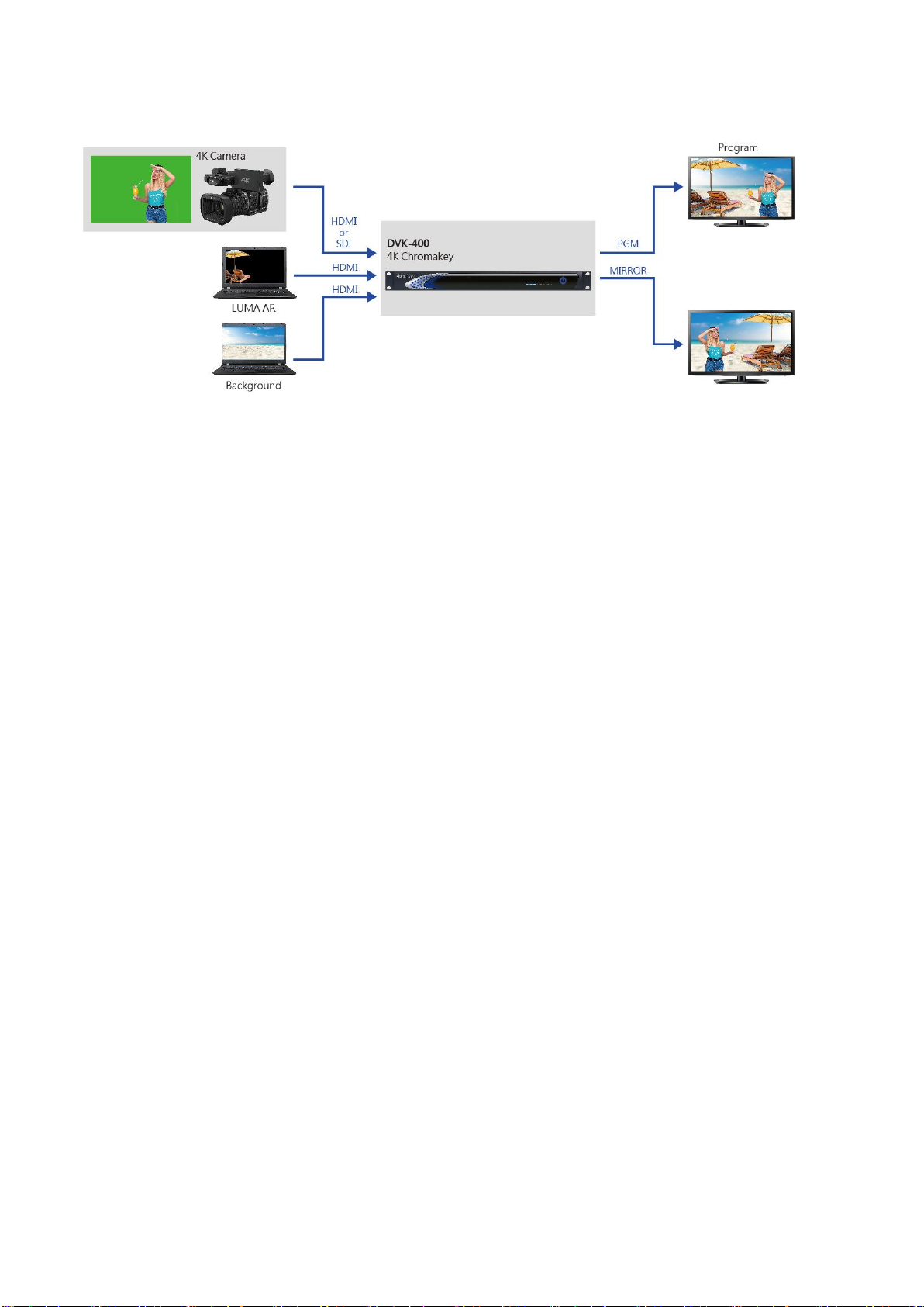
The Datavideo DVK-400 is an advanced 4K Chromakey for presenting perfect chromakey effect
with its easy-to-use user interface.
The Datavideo DVK-400 allows users to use it by connecting to the Notebook PC locally. Moreover,
it can be used by connecting to the IP network remotely.
The Datavideo DVK-400 can be used in the live events applications which are based on HDMI and
SDI videos. Moreover, the DVK-400 supports the video chromakey for up to 4K resolution and it
also provides easy-to-use Spill Suppression and Color Enhancement features for users.
1.1 Features
Supports 4K real-time chromakey with 4:4:4 color sampling and 10-bit color depth.
Supports Easy Operation and Control via LAN connection to a Notebook PC.
Supports advanced algorithm for presenting transparency, smoke, reflection and shadow in
detail.
Supports easy-to-use Spill Suppression function.
Supports full foreground post-processing for achieving natural synthesis with background.
Supports multiple HDMI and SDI outputs for Program and Preview with Mirror option.
Supports User Memory Preset function.
Supports Chromakey Noise Reduction function.
Supports Matte Control function for adjusting the Black Level and White Level for achieving
precise chromakey for eliminating the reflective color from the foreground.
Supports Dark Enhancement/Bright Enhancement and Shadow Enhancement Functions.
Supports post-processing for calibrating Brightness, Contrast, Saturation parameters for
applying those parameters to the foreground signal after chromakey processing.
Supports Garbage Mask with Soft edge.
Supports Auto Chromakey function.
Supports PGM Mirror Function.
6
Page 7
Chapter 2 System Diagram
7
Page 8
Interface
Description
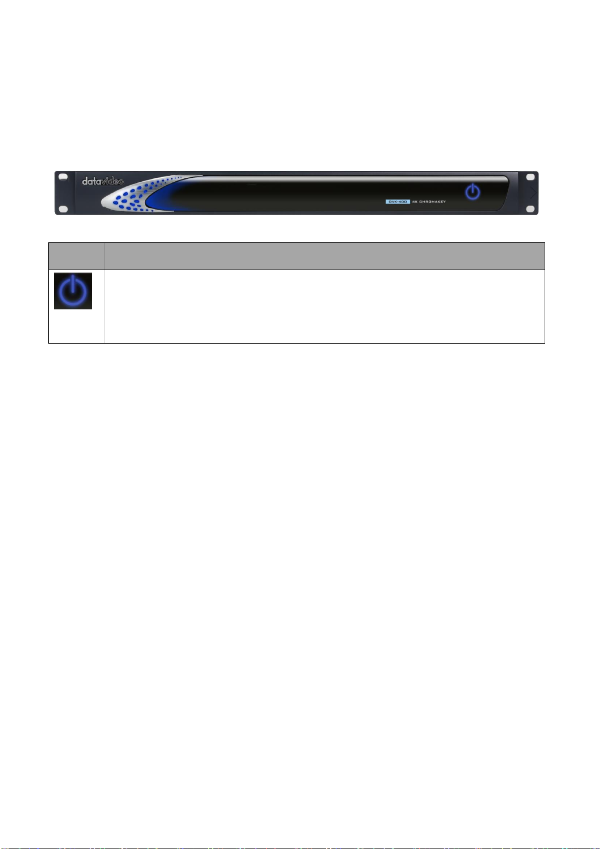
This is the power button which is located at the front panel. Please turn on the power
switch which is located at the rear panel of the DVK-400 and then please press this
button to turn on the power of the DVK-400.
Chapter 3 Connection
This part will show users the way for connecting the Datavideo DVK-400 4K Chromakey. Please
refer to following paragraphs for details.
3.1 Front View
8
Page 9
3.2 Rear View
Interface
Description
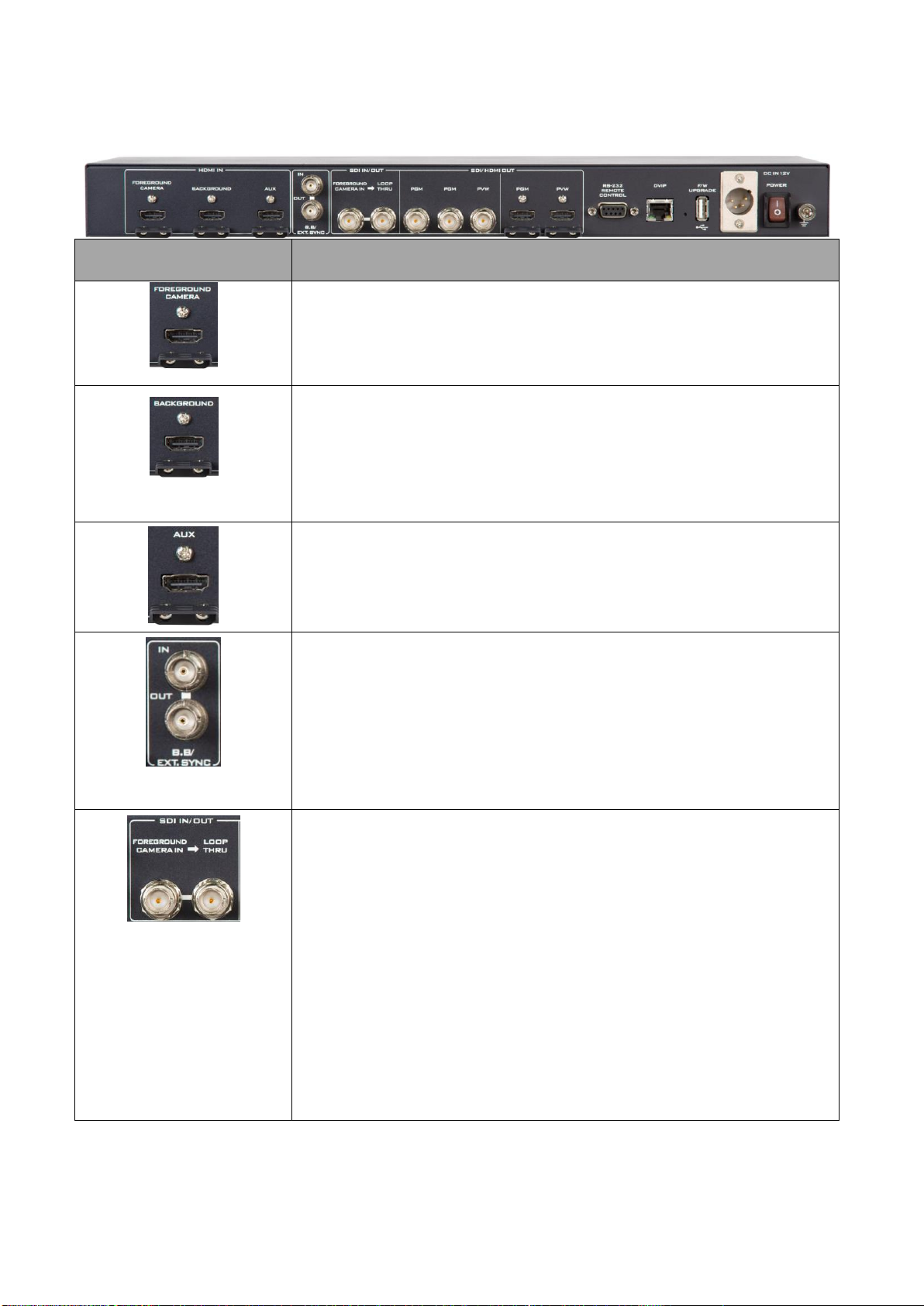
FOREGROUND CAMERA
Please connect the camera for shooting the foreground subject to this
HDMI interface.
BACKGROUND
After the subject image is chromakeyed, please connect the HDMI
input source which is used to be the background source to this
interface.
AUX
This interface allows users to connect to the HDMI interface of the
notebook PC for the Logo icon input.
B.B EXT. SYNC
When there is a B.B or a tri-level sync signal which is connected to be
the input signal for the DVK-400 4K Chromakey, it can be a reference
source of the video output synchronization.
SDI IN/OUT
FOREGROUND CAMERA IN
Please connect the foreground camera for shooting the foreground
subject to this SDI interface.
LOOP THRU
This interface can connect to an external connected monitor for
looping the FOREGROUND CAMERA IN input signal directly to the
external connected monitor.
9
Page 10
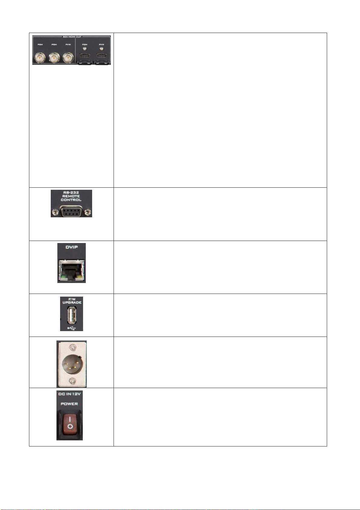
SDI/HDMI OUT
PGM
This interface can be connected to an external connected monitor for
transmitting the new video which is combined by the foreground
video and the new background after the foreground video is
chromakeyed.
PVW
This interface can be connected to an external connected monitor for
previewing the new image which is combined by the foreground and
the new background after the original foreground video is
chromakeyed.
RS-232 REMOTE CONTROL
Please connect an RS-232 to USB adapter cable from this interface to
your notebook PC for controlling the DVK-400 4K Chromakey
remotely.
DVIP
Please connect an RJ-45 Ethernet cable from this interface to the RJ45 interface of your laptop for controlling the DVK-400 4K Chromakey
by the DVIP protocol.
F/W UPGRADE
This interface is used for updating the firmware by connecting a USB
thumb drive only.
12V Power Interface
Please connect a 12V DC power cable to this interface for supplying
power for the DVK-400 4K Chromakey.
DC IN 12V POWER Switch
This is the DC IN 12V power switch of the DVK-400.
10
Page 11
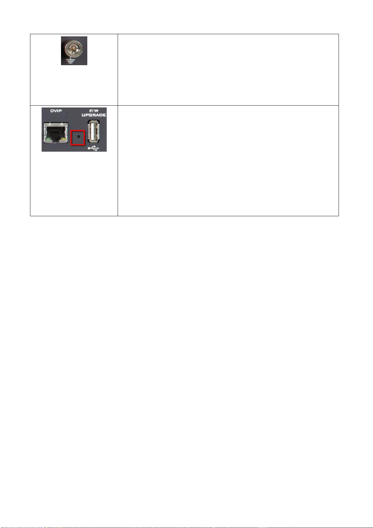
Ground
When connecting this device to any other component, please make
sure that it is connected via this end. Please point this end to other
suitable points for proper grounding. When connected, please use
this interface and please make sure to use a socket and use a wire
with a cross-section of at least 1.0mm2.
IP Address Reset Hole
When the DVK-400 is connected to a PC by the static IP address, if the
IP address of the DVK-400 can not be scanned by users, it is possible
that this DVK-400 was set in DHCP mode. To solve this issue, please
press the IP RESET hole on the rear panel of the DVK-400 by a sharp
object and then please wait for about 5 seconds for releasing the
pressing. After that, the IP address of the DVK-400 will be resumed to
factory default static IP address, 192.168.100.120. And then users can
scan the DVK-400 IP address for re-connecting.
11
Page 12

Chapter 4 Basic Setup
Before using the DVK-400 for chromakeying, it is necessary for users to set the DVK-400 up in
advance. Please follow following steps for setting the basic setup of the DVK-400.
1. Please use an HDMI cable to connect from the foreground camera input source to the
“FOREGROUND CAMERA” HDMI interface. If there is SDI interface only for your foreground
camera, please use a SDI cable to connect the foreground camera to the “CAM IN” SDI interface
on the rear panel of the DVK-400.
1. Please use an HDMI cable to connect from the foreground camera input source to the
“FOREGROUND CAMERA” HDMI interface on the rear panel of the DVK-400. If there is an SDI
interface only for your foreground camera, please connect the foreground camera to the “CAM
IN” SDI interface on the rear panel of the DVK-400 through an SDI cable.
2. Please use an HDMI cable to connect from your background video source to the
“BACKGROUND” interface on the rear panel of the DVK-400. In this example, the HDMI input
source is the Notebook PC.
3. Please use an HDMI or an SDI cable to connect from the “PVW HDMI” or “PVW SDI” interface on
the rear panel of the DVK-400 to the HDMI interface of an external connected monitor to be the
monitor for monitoring the chromakey effect of the DVK-400.
Notes:
If users need an external connected mirroring screen, please use an HDMI cable to connect
from the “PGM HDMI” interface on the rear panel of the DVK-400 to the HDMI interface of
an external connected monitor and then this monitor can be used as an external
connected mirroring monitor.
If it is needed for users to input a Logo, please use an HDMI cable to connected from the
AUX interface on the rear panel of the DVK-400 to the HDMI interface of a laptop.
If it is needed to use the DVIP protocol to control the DVK-400, please use an RJ-45
Ethernet cable to connect from the RJ-45 Ethernet interface of your laptop to the DVIP RJ45 Ethernet interface on the rear panel of the DVK-400.
If it is needed to use the RS-232 interface to control the DVK-400, please use a D-sub 9 pin
to USB adapter cable to connect from the RS-232 REMOTE CONTROL interface on the rear
panel of the DVK-400 to the USB interface of your laptop.
After those steps are finished, the hardware setup procedure for the DVK-400 is completed.
12
Page 13
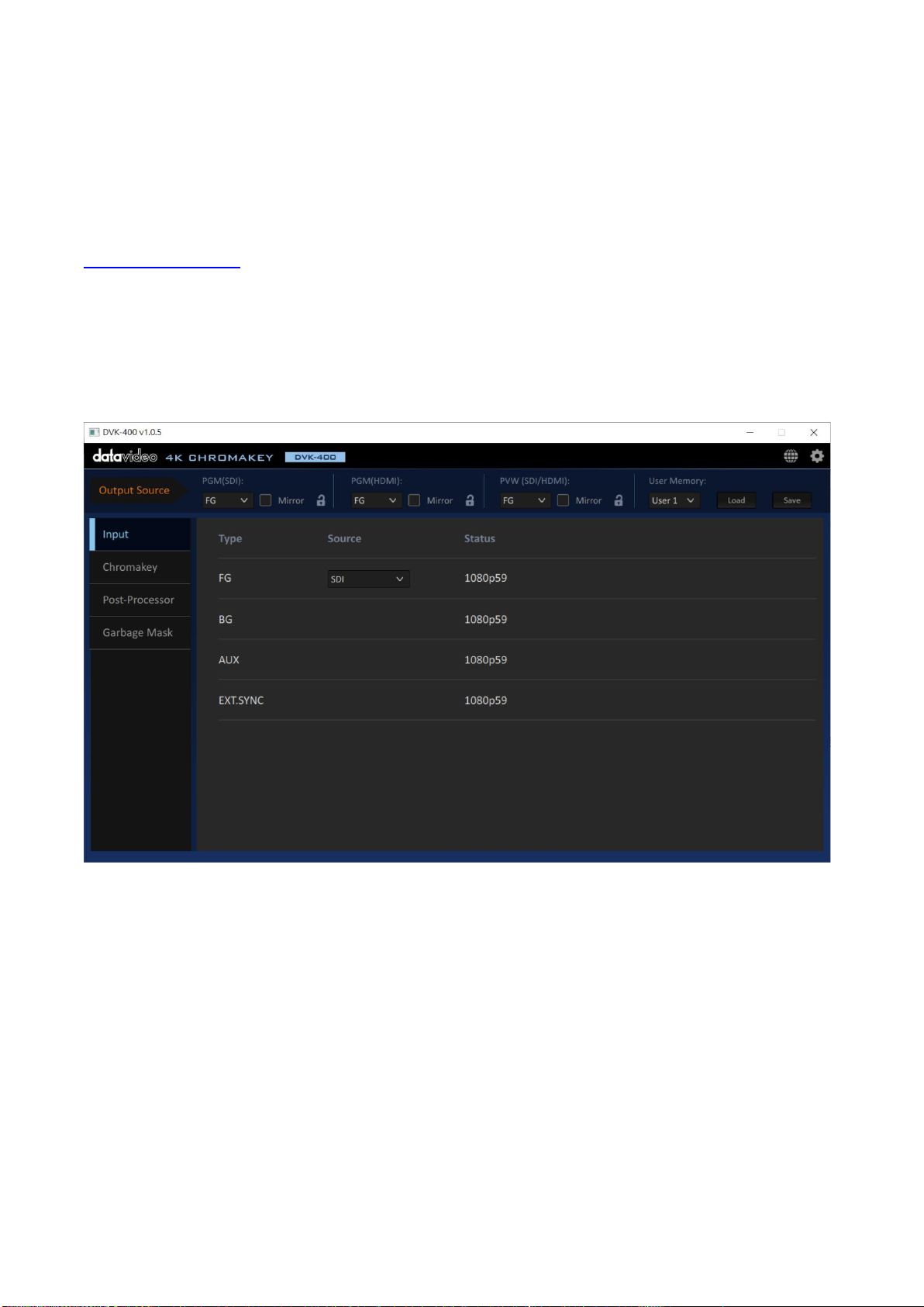
Chapter 5 DVK-400 4K Chromakey Control Software
5.1 How to Launch the DVK-400 4K Chromakey Control Software
Please follow following steps for launching the DVK-400 4K Chromakey control software.
1. Please download the DVK-400 4K Chromakey control software from Datavideo official website
www.datavideo.com
2. Please unzip the DVK-400 4K Chromakey control software.
3. Please double-click the “DVK-400.exe” for launching the DVK-400 Chromakey control software
interface which is shown as following diagram.
13
Page 14
5.2 How to Set the Network Related Settings for the DVK-400 4K Chromakey
Before the operation of the DVK-400 4K Chromakey control software, it is necessary for users to
set the way for controlling the DVK-400 and to connect the DVK-400 to the notebook for operating
the DVK-400 4K Chromakey control software. Please follow following steps for setting the network
related settings of the DVK-400.
Connect by the DVIP Protocol
1. Please make sure that there is an RJ-45 Ethernet cable connected from the RJ-45 interface of
your notebook PC to the DVIP RJ-45 Ethernet interface on the rear panel of the DVK-400.
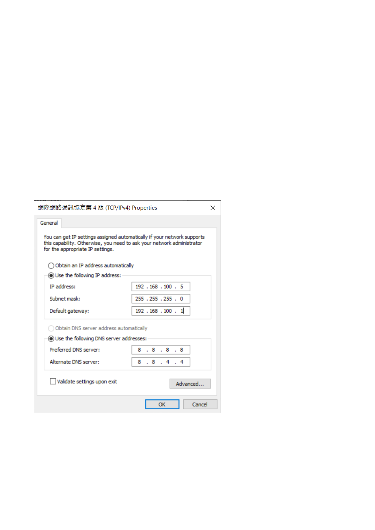
2. The default static IP address of the DVK-400 is 192.168.100.120. If the DVK-400 is connected to
your notebook PC by the Ethernet cable directly, please set the network setting of your notebook
PC in static IP mode in advance. Moreover, please set the static IP address of your notebook PC in
the same Local Area Network (LAN) with the DVK-400 which is shown as following example.
14
Page 15
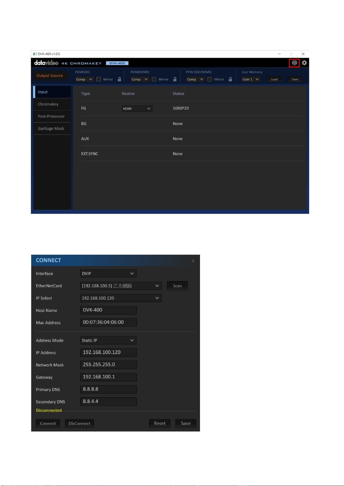
3. Please click the “Globe” icon which is located on the top-right side of the interface.
4. The CONNECT control interface will be shown.
15
Page 16
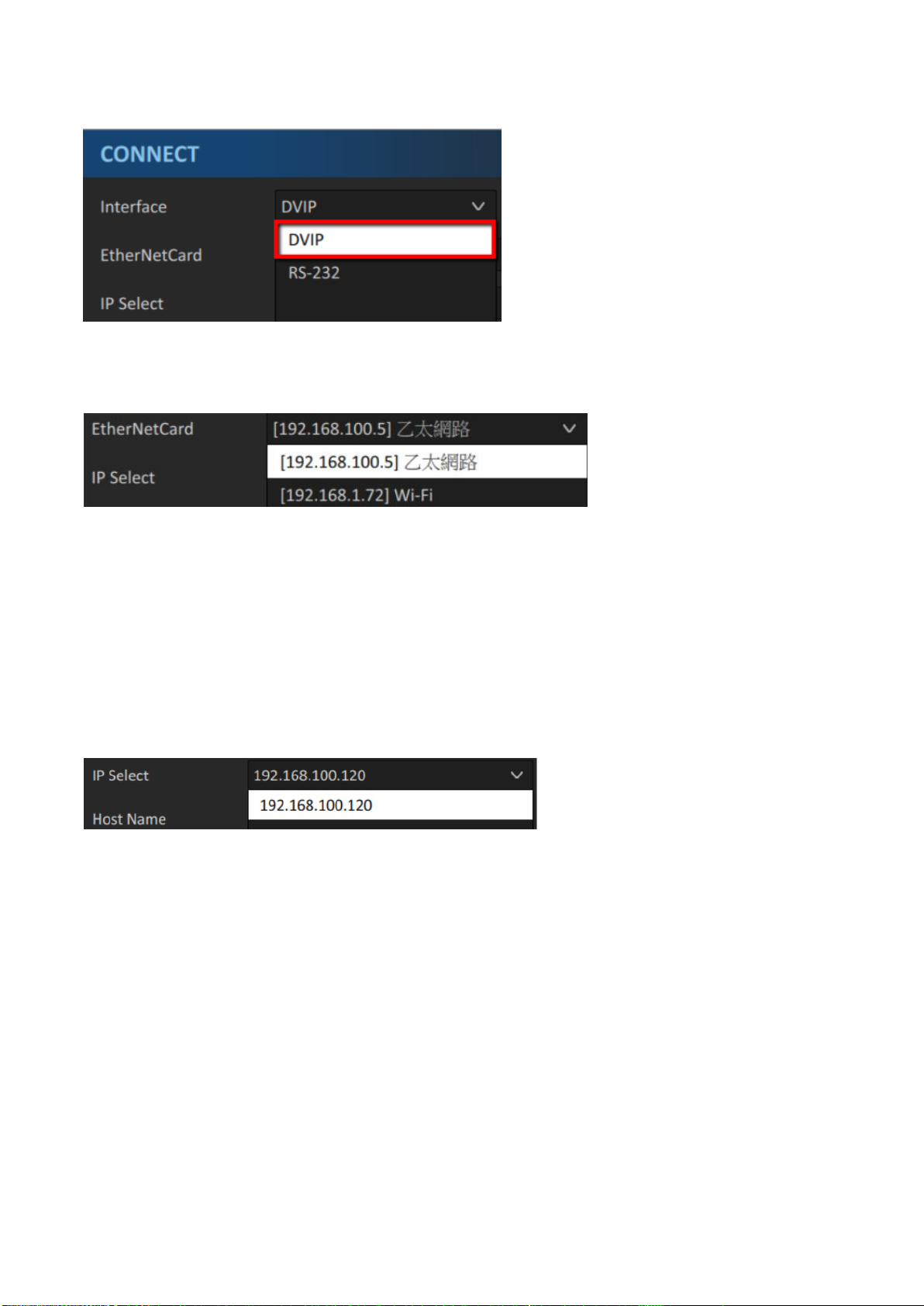
5. Please select DVIP from the “Interface” drop-down menu.
6. The Ethernet Card which is found by the PC will be shown on the EtherNetCard option. Please
select the Ethernet Card which is used to connect to the DVK-400 from the drop-down menu.
7. When the DVK-400 is used for the first time, please remember to press the “Scan” button which
is located on the right side of the “EtherNetCard” option for the App to search IP addresses of all
connected DVK-400s within the same Local Area Network (LAN). In the searching process, the
word “Scanning” will be shown on the bottom-left side of the CONNECT dialogue box.
8. Please select the IP address of the DVK-400 that you want to connect from the IP Select option.
After that, the messages including the Host Name=DVK-400, Mac Address, Address Mode, IP
Address will be shown.
16
Page 17
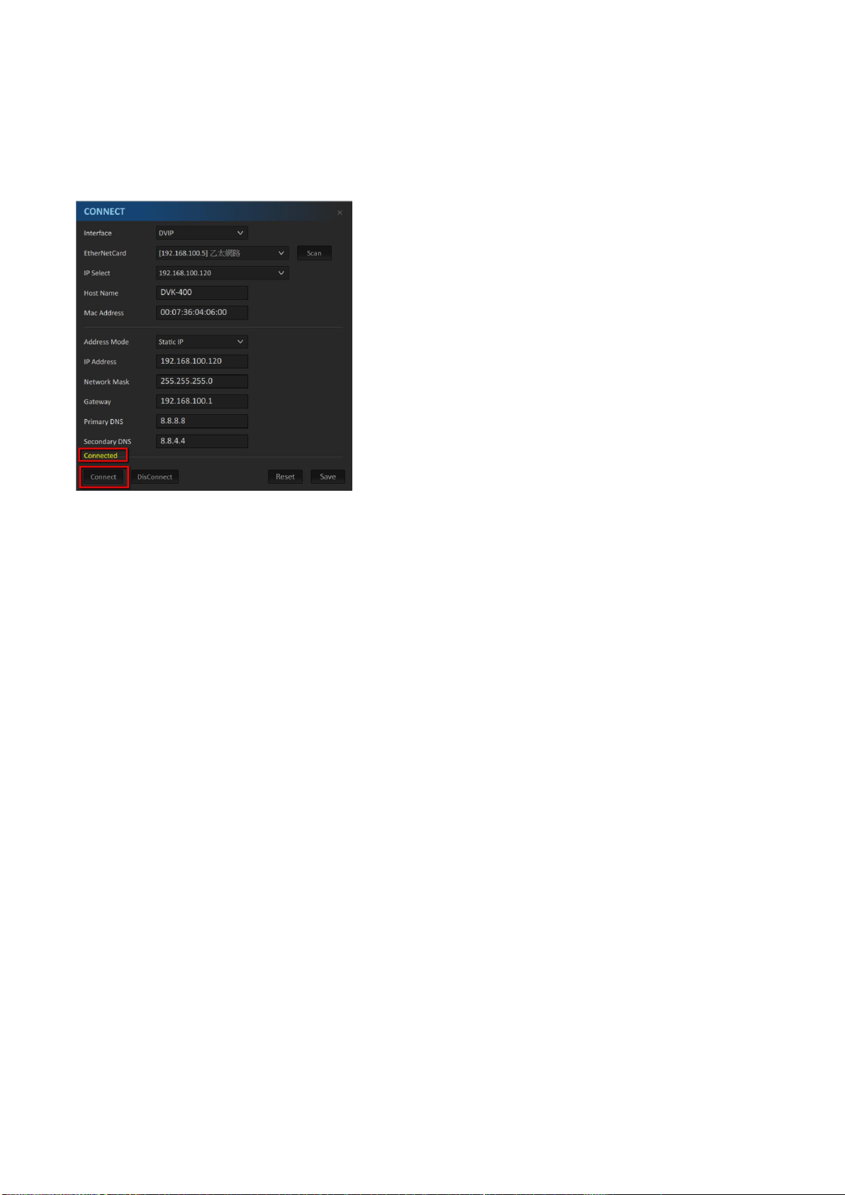
9. Please press the “Connect” button and then please wait until the word “Connected” is shown in
yellow for showing that the DVK-400 and the control software are connected successfully.
Note: When the “Connect” button is pressed and the connection is established, the CONNECT
dialogue box will be closed automatically.
Note: If the Address Mode is needed to be modified to be Static IP/DHCP settings or the IP address
of the Static IP is needed to be modified, please press the “Save” button. After the “Saving”
message disappears, the message “DVK-400 is configured. Please scan to refresh” will be shown.
Users need to turn off and then turn on the power of the DVK-400. After the DVK-400 control
software interface is shown, please press the Scan button again to select the right IP address from
the IP Select option again for taking effect the modification.
17
Page 18
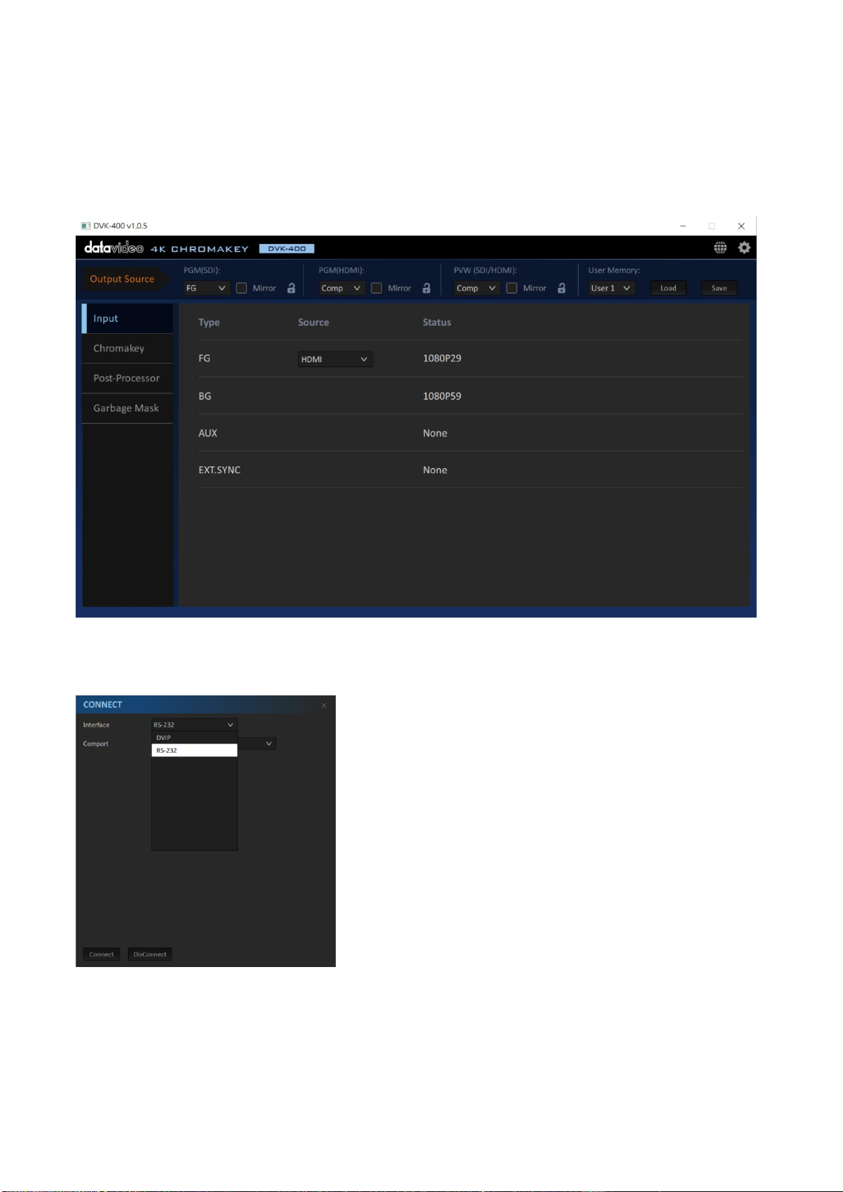
Connect by the RS-232 Interface
Please follow following steps for connecting the DVK-400 to the notebook PC by the RS-232
interface.
1. Please connect the RS-232 cable between the PC and the DVK-400. After that, please launch the
latest version of the DVK-400 control App.
2. Please click the Globe icon which is located on the top-right side. After that, please select RS-
232 from the Interface drop-down menu.
3. The “Comport” option will show the COM port list which is detected by the system. Please
select the connected COM port from the drop-down menu.
18
Page 19
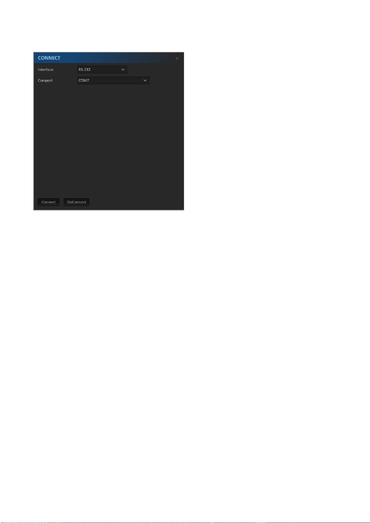
4. Please press the “Connect” button for connecting and then please wait until the CONNECT
dialogue box is closed.
Note:
1. If the RS-232 to USB adapter cable is used by users, please make sure that this cable is
connected properly before opening the DVK-400 control App for seeing the COM port in the
Comport list. Please select the right COM port and then press the “Connect” button. If the
connection is failed, the CONNECT dialogue box will not be closed and there is an error
message that will be shown on the bottom-right corner of the App. Users need to check
whether the connection is correct or not and to check that whether the RS-232 interface is
occupied by other software or not.
19
Page 20
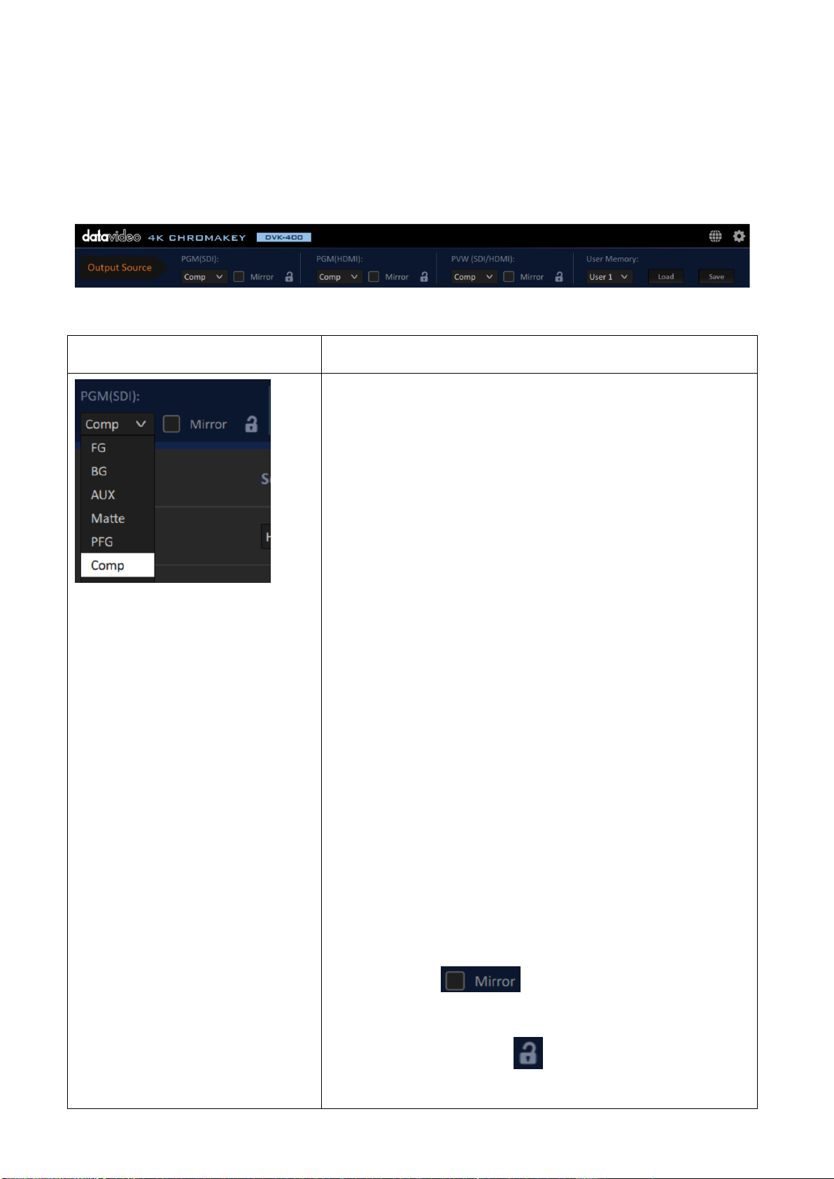
5.3 Introduction of the DVK-400 4K Chromakey Control Software Interface
Option
Description
PGM(SDI)
The PGM (SDI) drop-down menu allows users to select what
kind of output source must be used for the PGM SDI
interface if the PGM SDI interface is connected. Those output
sources can be divided into following categories.
FG:This option allows users to output the
FOREGROUND CAMERA video source.
BG: This option allows users to output the
BACKGROUND video source.
AUX: This option allows users to output the video source
from the AUX interface.
Matte: This is the FG Black and White MATTE. Full
Black=Remove, Full White=Solid, Gray=translucent
PFG:The PFG is the Processed-Foreground. The
background color of the foreground image will become
gray or will be color reproduced.
Comp: This is the FOREGROUND+BACKGROUND
composite picture.
*If the “Mirror” is checked, the output source
will be mirroring in left and right reversal.
*If users click the lock icon and then the output source
can not be changed.
Please see following paragraphs for the introduction of the DVK-400 4K Chromakey Control
Software interface.
Output Source: The main interface of the Output Source option is shown as following
diagram.
20
Page 21
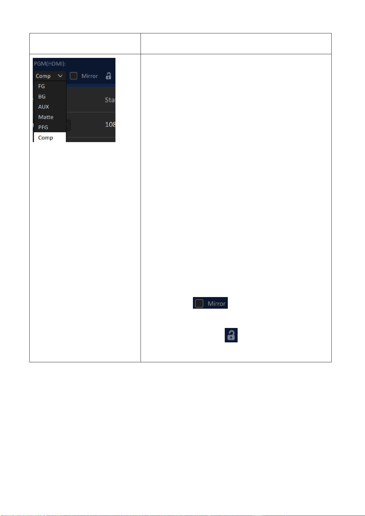
PGM(HDMI)
The PGM(HDMI) drop-down menu allows users to select
what kind of output source must be used for the PGM HDMI
interface if the PGM HDMI interface is connected. Those
output sources can be divided into following categories.
FG:This option allows users to output the
FOREGROUND CAMERA video source.
BG: This option allows users to output the
BACKGROUND video source.
AUX: This option allows users to output the video source
from the AUX interface.
Matte: This is the FG Black and White MATTE. Full
Black=Remove, Full White=Solid, Gray=translucent
PFG:The PFG is the Processed-Foreground. The
background color of the foreground image will become
gray or will be color reproduced.
Comp: This is the FOREGROUND+BACKGROUND
composite picture.
*If the “Mirror” is checked, the output source
will be mirroring in left and right reversal.
*If users click the lock icon and then the output source
can not be changed.
21
Page 22
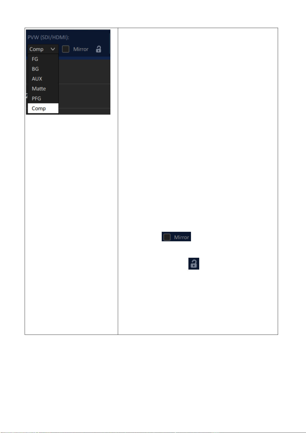
PVW(SDI/HDMI)
The PVW(SDI/HDMI) drop-down menu allows users to select
what kind of output source must be used for the PVW SDI or
PVW HDMI interface. Those output sources can be divided
into following categories.
FG:This option allows users to output the
FOREGROUND CAMERA video source.
BG: This option allows users to output the
BACKGROUND video source.
AUX: This option allows users to output the video source
from the AUX interface.
Matte: FG This is the FG Black and White MATTE. Full
Black=Remove, Full White=Solid, Gray=translucent
PFG:The PFG is the Processed-Foreground. The
background color of the foreground image will become
gray or will be color reproduced.
Comp: This is the FOREGROUND+BACKGROUND
composite picture.
*If the “Mirror” is checked, the output source
will be mirroring in left and right reversal.
*If users click the lock icon and then the output source
can not be changed.
* When sampling the screen color automatically or manually,
the PVW screen will show the FG screen temporarily.
Moreover, the sampling cursor (+) will be shown. After the
color sampling is finished, it will switch back to the PVW
screen.
22
Page 23
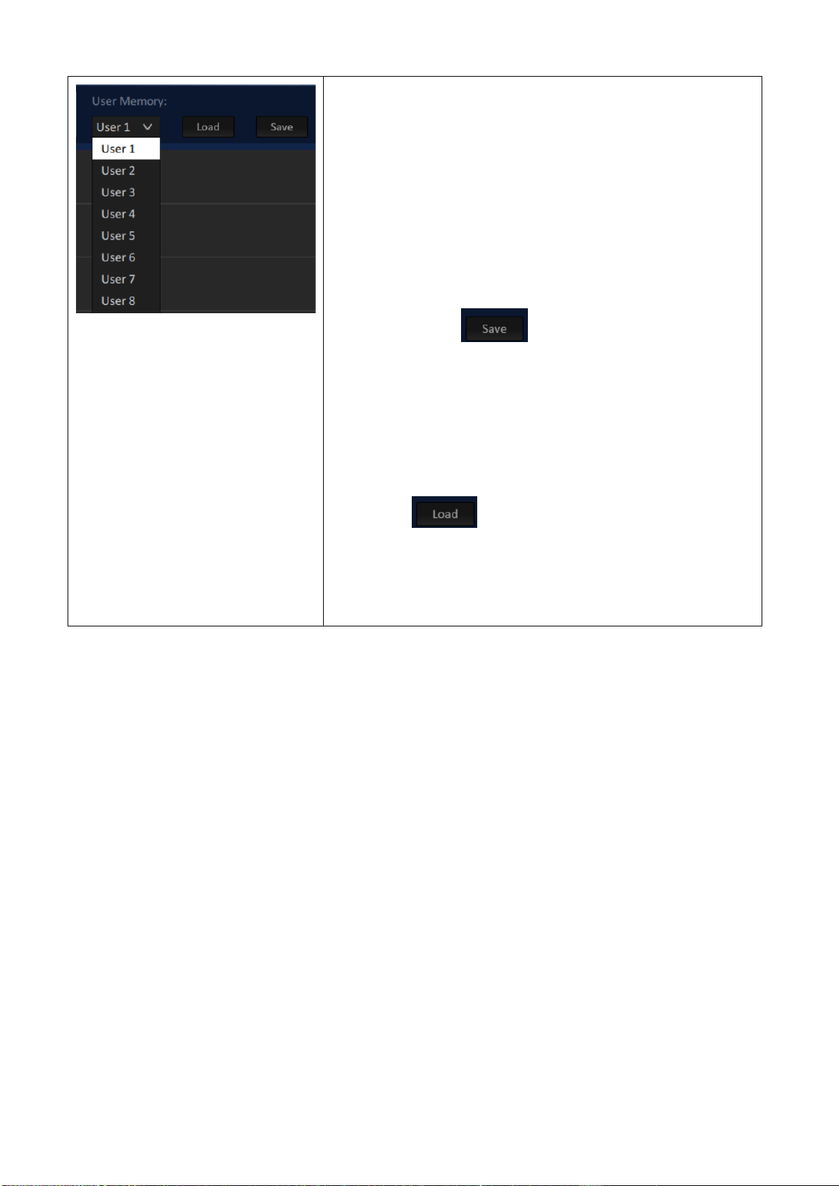
User Memory
This User Memory function allows users to store current
settings and then users can recall those settings in the future.
There are 8 settings including User 1 to User 8 for users to
store their desired settings.
If users want to store current settings
Please modify different setting respectively. After that,
please select User 1 to User 8 and then please press the
“Save” button . Please wait until the word
“Setting completed” is shown and then it means the
saving is finished.
If users want to load pre-saved settings.
Please select the User number for your pre-saved
settings. After that, please press the “Load”
button . Please wait until the word “Setting
completed” is shown and then it means that the loading
is finished.
23
Page 24
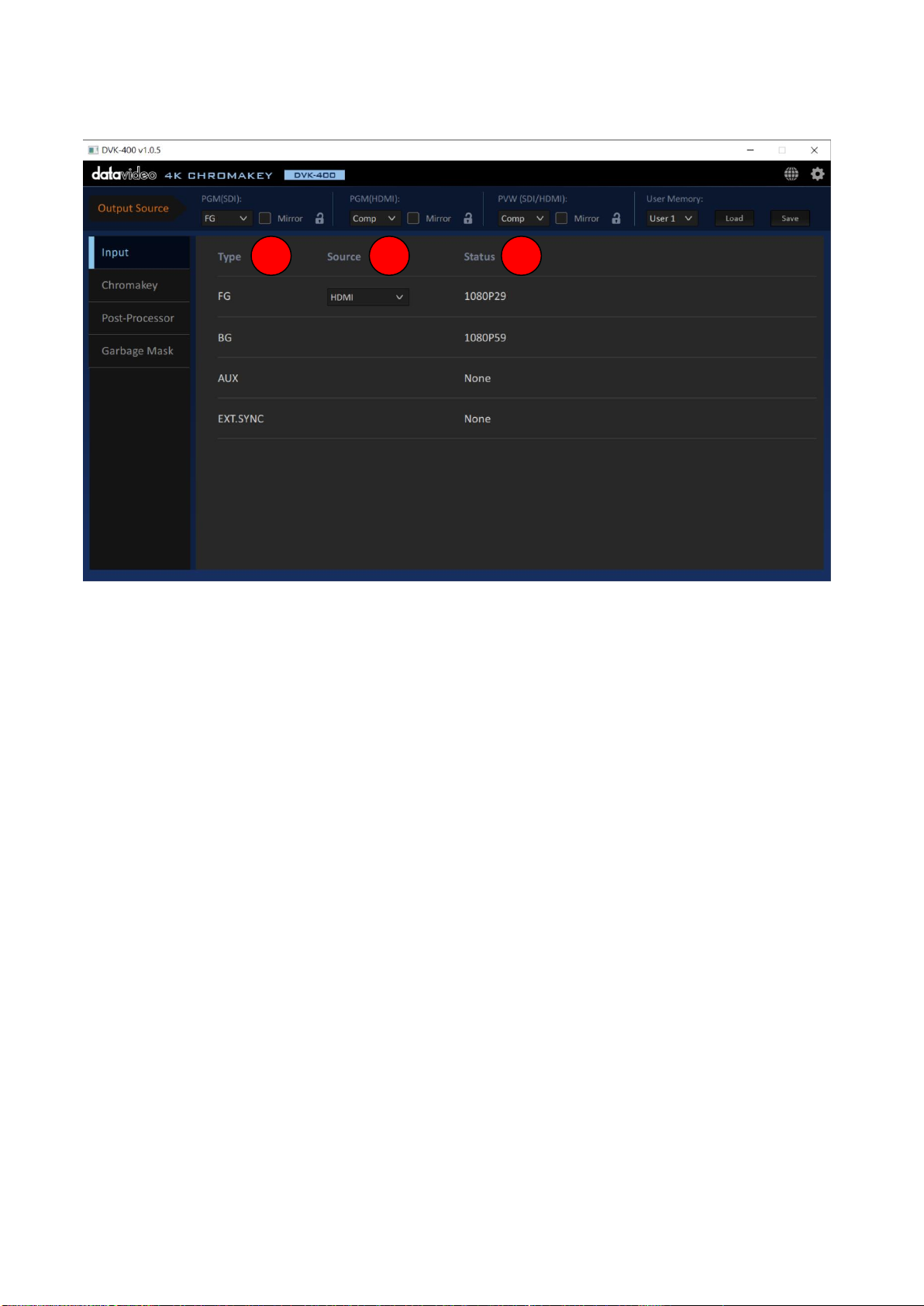
Input option: The main interface of the Input option is shown as following diagram.
1 2 3
1. Type: This option lists DVK-400’s input interfaces including FG/BG/AUX interface and EXT.SYNC
interface.
2. Source: After the DVK-400 is connected successfully by the DVIP or RS-232 protocol, this option
will show the type of the connected Foreground interface such as SDI or HDMI.
3. Status: After the DVK-400 is connected successfully, this option will show the resolution of
connected foreground camera or background. If the AUX or EXT.SYNC interface is connected, this
option will also show the status of those interfaces.
24
Page 25
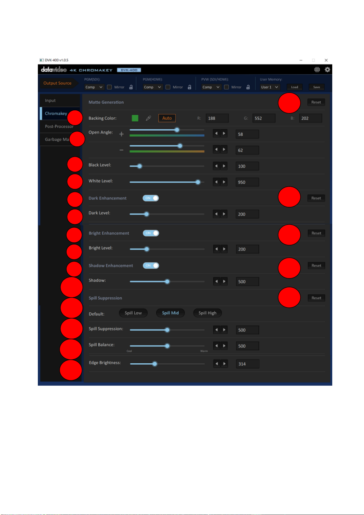
Chromakey Option: The main interface of Chromakey is shown as following diagram.
1
2 3 4 5 6
7
8
9
10
11
12
13
14
15
15
15
15
15
25
Page 26
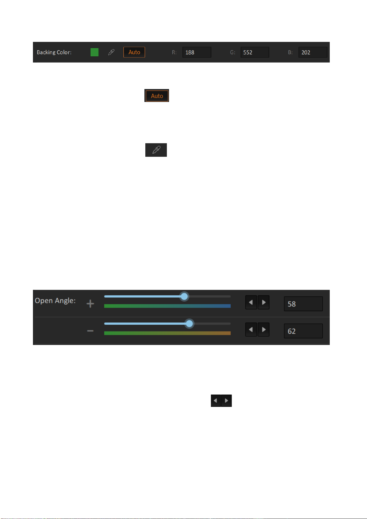
1. Backing Color:
This option provides Auto color sampling (dropper) and manual color sampling for users. Generally
speaking, the Auto color sampling is sufficient for users.
Auto: Please press the “Auto” button and then users will see that the FG is shown on the
PVW OUT for about 2 seconds. Moreover, users will see that the “+” is shown and moved on the
screen for color sampling. It will calculate the screen color (Green Screen, Blue Screen or others)
and then it will reset all parameters on the Chromakey page to default values automatically.
Manual: Please click the dropper icon for users to select the color of the green screen or
blue screen which is located behind the foreground subject. At this time, the “Pick Back Color”
background color selection window will be shown. When the mouse cursor is moved, there is a
“+” that will appear to move with the cursor. The screen will switch to Foreground PVW OUT
screen for users to see the “+” character. Please move the “+” to the reference color area and
then please click the mouse once. After that, please press “Auto” to confirm the selected screen
color. At this time, it will reset all parameters on the Chromakey page to default values. If the “OK”
button is pressed by users, only the screen color will be changed and other parameters will not be
changed.
Note: If the Saturation or Brightness of the green/blue is lower than 20%, it is possible that the
“Auto” automatic color sampling will be failed and users can not see the color change from the
screen. In order to solve this issue, users need to improve the lighting and the camera settings.
2. Open Angle:
This “Open Angle” option allows users to set a certain degree of the color range in the color wheel
to be the chromakey range. (Generally speaking, the default +/-60 is sufficient for users. Only
when there are yellow/green objects become translucent, then users need to decrease the degree
range to modify those yellow/green objects to solid. Users can adjust the value of the “Open
Angle” option by sliders or left-arrow & right-arrow buttons .
26
Page 27
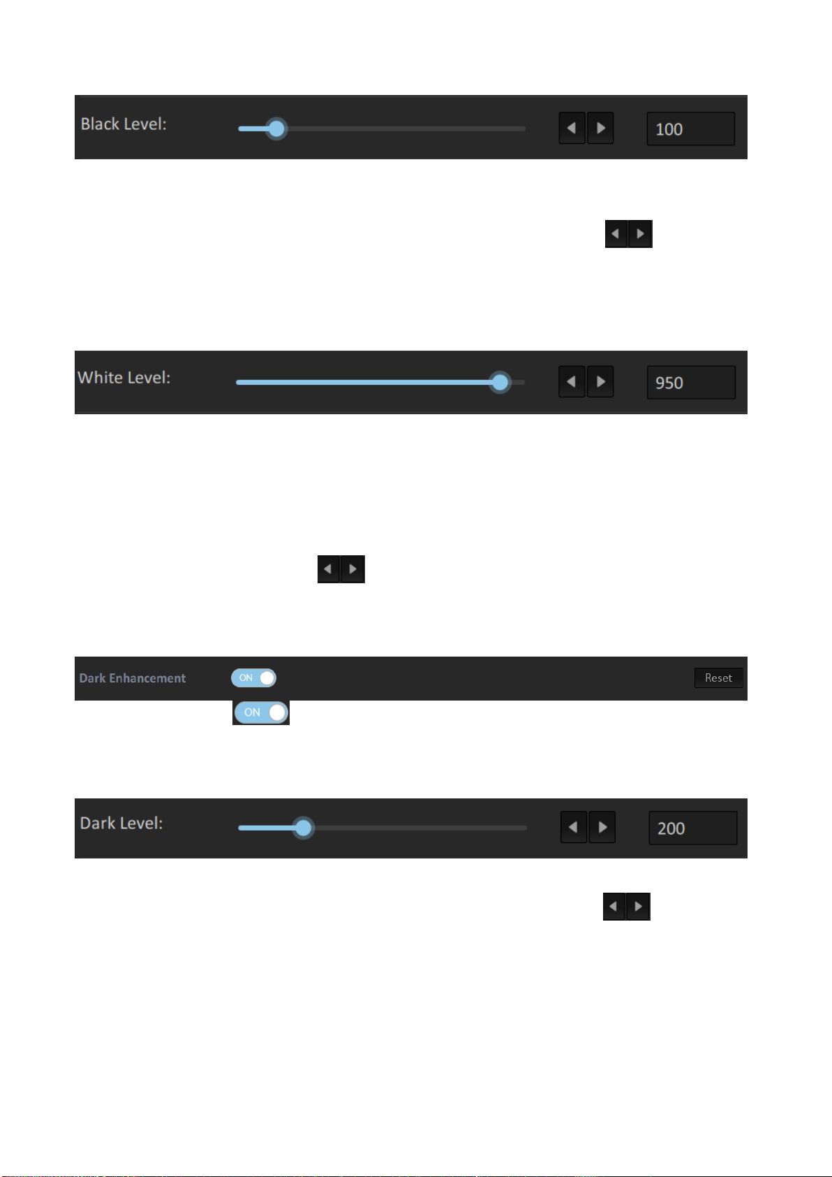
3. Black Level:
Please slide the Black Level slider to the right side or press the right-arrow button to increase the
black level for eliminating the uneven situation in the composite screen. If the PVW OUT is
switched to Matte output, users can see that there are more areas which are eliminated and
become black. Users can use the slider or the left-arrow or right-arrow button to adjust the
value of the Black Level option.
4. White Level:
If the green/blue is reflected on the object, it can make more transparent objects to become
translucent or to become more solid. (Generally speaking, the best Black Level should be 100~400.
If the Cleanliness is too high, it will decrease the detail of the composite screen. It is recommended
to improve the lighting of the environment. The White Level must be higher than the Black Level.
The best difference is that the White Level value must be 300 higher than the Black Level for
achieving more natural effect. Users can adjust the value for the White Level option by using the
left arrow or the right arrow button . If the PVW OUT is switched to Matte, users can see
that more areas become solid and the color is changed to white.
5. Dark Enhancement:
Please press the switch which is located next to the Dark Enhancement option to launch
the Dark Enhancement function.
6. Dark Level
(Default Level = 200). If the Dark Level is increased, the black object or hair will become more
apparent. Users can use the slider of the left-arrow or the right-arrow button for adjusting
the value of the Dark Level option.
27
Page 28
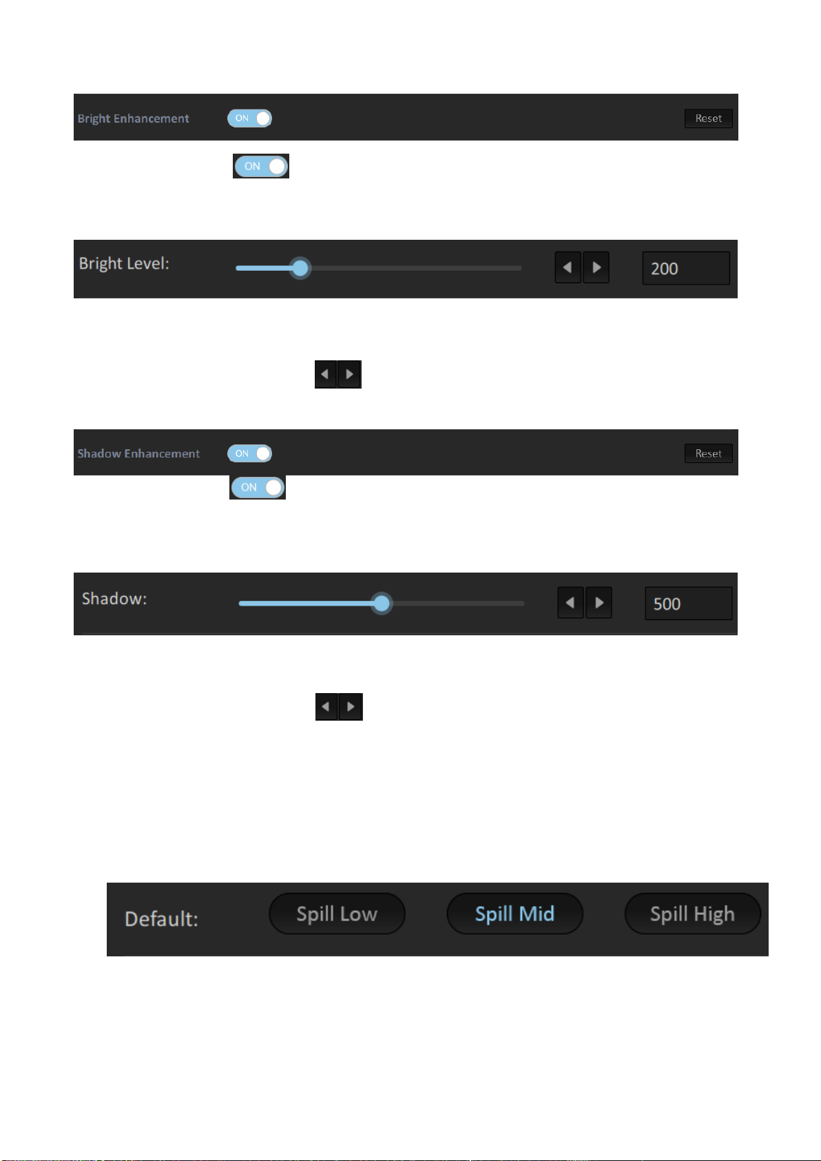
7. Bright Enhancement:
Please press the switch which is next to the Bright Enhancement to launch the Bright
Enhancement function.
8. Bright Level:
Bright Level: (default Level=200). If the Bright Level is increased, the transparent object, glass or
smoke will become more apparent. Users can adjust the value of the Bright Level option by using
the left-arrow or right arrow button .
9. Shadow Enhancement:
Please press the switch which is located next to the Shadow Enhancement to launch the
Shadow Enhancement function.
10. Shadow Level:
In special situation, users can use shadow for creating shadow on the ground or to restore the fine
black hair. (If users don’t need this function, please shut down this function). Users can use the
left-arrow or the right-arrow button to adjust the value of the Shadow Level.
11. Spill Suppression:
Default: The Spill Suppression option of the DVK-400 provides users three default Spill
Suppression level including “Spill Low”, “Spill Mid” and “Spill High”. Users can push one
button for applying their desired Spill Suppression setting.
28
Page 29
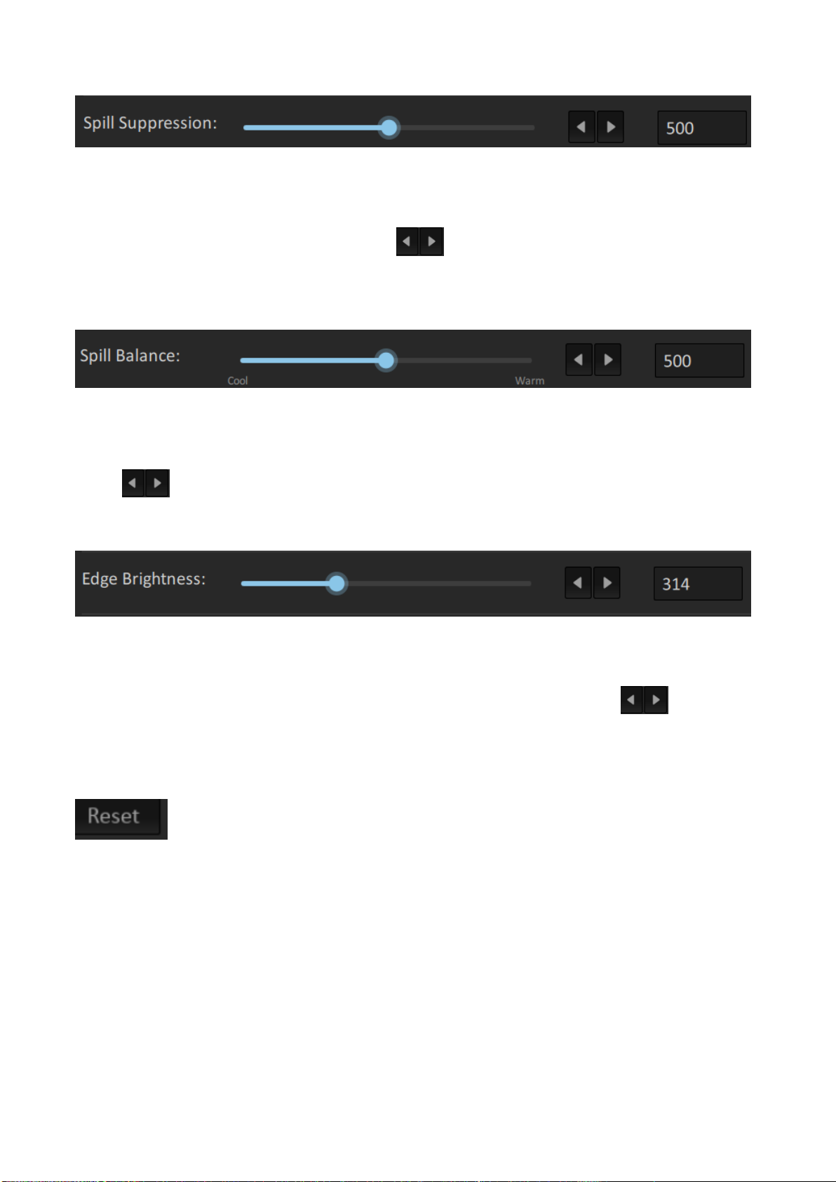
12. Spill Suppression:
The Spill Suppression option is used to restore the reflective green or blue. If the Spill Suppression
is increased, it can restore the reflective green or blue for the subject. Generally speaking, the
suitable Spill Suppression range is from 400 to 700. (The default value is 500). Users can use the
slider, the left-arrow or the right arrow button to adjust the value of the Spill Suppression
option.
13. Spill Balance:
If the Spill Balance value is increased, the skin tone will be biased towards warm colors. If the Spill
Balance value is decreased, the skin tone will be biased towards cool colors. The suitable Spill
Balance value is 500. Users can use the slider, the left-arrow button or the right-arrow
button to adjust the value of the Spill Balance option.
14. Edge Brightness:
Users can adjust the Edge Brightness for making the Edge Brightness to be closer to the
background color. If the Edge Brightness value is too low, it will make the black edge to become
darker. Users can use the slider, the left-arrow button or the right-arrow button to adjust
the value of the Edge Brightness option.
15. Reset:
Please press this Reset button for resetting related options.
29
Page 30
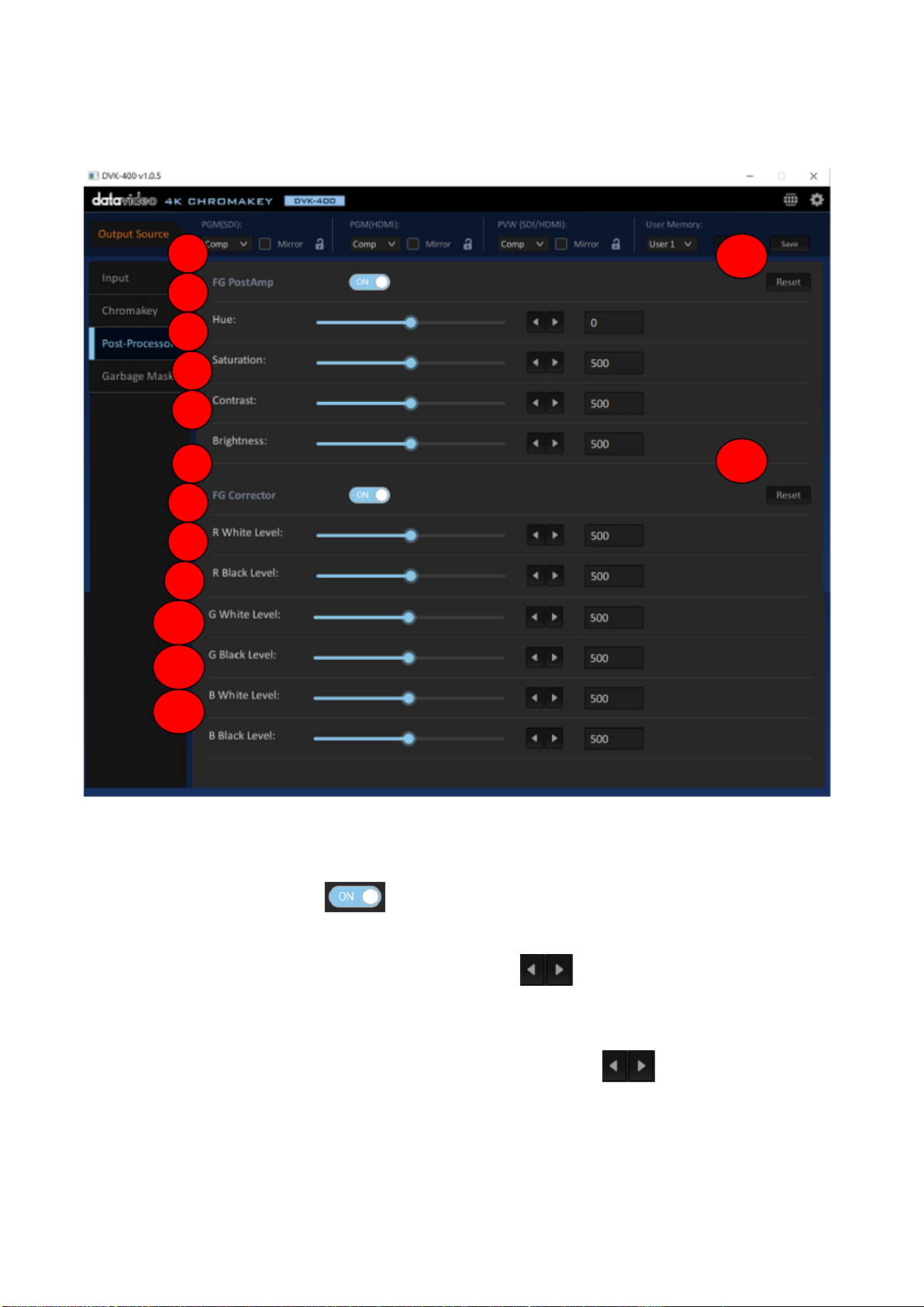
Post Processor:The main interface of the Post Processor is shown as following diagram.
1 2 3
4
5
6 7 8
9
10
11
12
13
13
1. FG PostAmp:
FG PostAmp: Please press the to launch the FG PostAmp function.
2. Hue: This option is used for the adjustment of the Hue for the foreground screen. Users can use
the slider, the left-arrow button or the right-arrow button to adjust the value of the Hue
option.
3. Saturation: This option is used for the adjustment of the Saturation for the foreground screen.
Users can use slider, the left-arrow button or the right-arrow button to adjust the value for
the Saturation option.
4. Contrast: This option is used for the adjusting of the Contrast for the foreground screen.
5. Brightness: This option is used for adjusting the Brightness of the foreground screen.
30
Page 31
6. FG Corrector: This option is used for RGB color calibration. Please click the to launch
the FG Corrector function.
7. R White Level: This option is used for Red White Level calibration. Users can use the slider, the
left-arrow button and the right-arrow button to adjust the value of the R White Level
option.
8. R Black Level: This option is used for Red Black Level calibration. Users can use the slider, the
left-arrow button and the right-arrow button to adjust the R Black Level option.
9. G White Level:This option is used for Green White Level calibration. Users can use the slider,
the left-arrow button and the right-arrow button to adjust the value of the G White Level.
10: G Black Level:This option is used for Green Black Level calibration. Users can use the slider,
the left-arrow button and the right-arrow button to adjust the value of the G Black Level.
11. B White Level:This option is used for Blue White Level calibration. Users can use the slider,
the left-arrow button and the right-arrow button to adjust the value of the B White Level.
12. B Black Level:This option is used for Blue Black Level calibration. Users can use the slider, the
left-arrow button and the right-arrow button to adjust the value of the B Black Level.
13. Reset:
Press this Reset button for resetting the related options.
31
Page 32
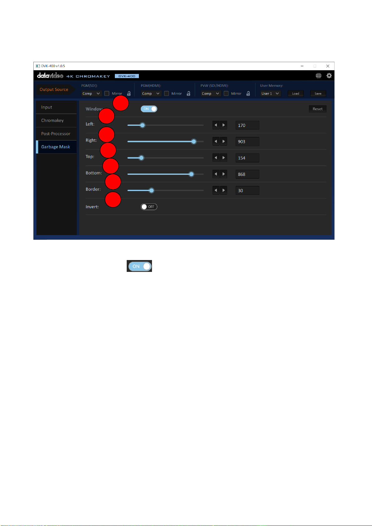
Garbage Mask Option: The main interface of the Garbage Mask is shown as following
1
2
3 4 5
6
7
diagram.
1. Windows:Please press the button to turn on/turn off the foreground matte display
range.
2. Left: This option allows users to adjust the left-side matte, the higher the value is, the more the
left-side edge of the foreground screen will be cropped.
3. Right: This option allows users to adjust the right-side matte, the higher the value is, the fewer
the right-side edge of the foreground screen will be cropped.
4. Top: This option allows users to adjust the top-side matte, the higher the value is, the more the
top-side edge of the foreground screen will be cropped.
5. Bottom: This option allows users to adjust the bottom side matte, the higher the value is, the
fewer the bottom-side edge of the foreground screen will be cropped. 。
6. Border: When the Border value becomes higher, the rectangular area will be expanded to
create a Rounded gradient soft edges from 0 to 100 degrees.
32
Page 33
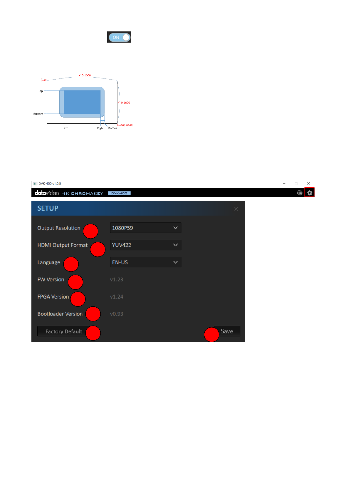
7. Invert: Please press the button to turn on/turn off the invert function. If the Invert
1 2 3 4 5
6
7
8
button is set to open and then the related cropping of the Garbage Mask will be done in reversal
direction.
Setup: The main interface of the Setup option is shown as following diagram. Please open the
main interface of the Setup option from following diagram.
33
Page 34
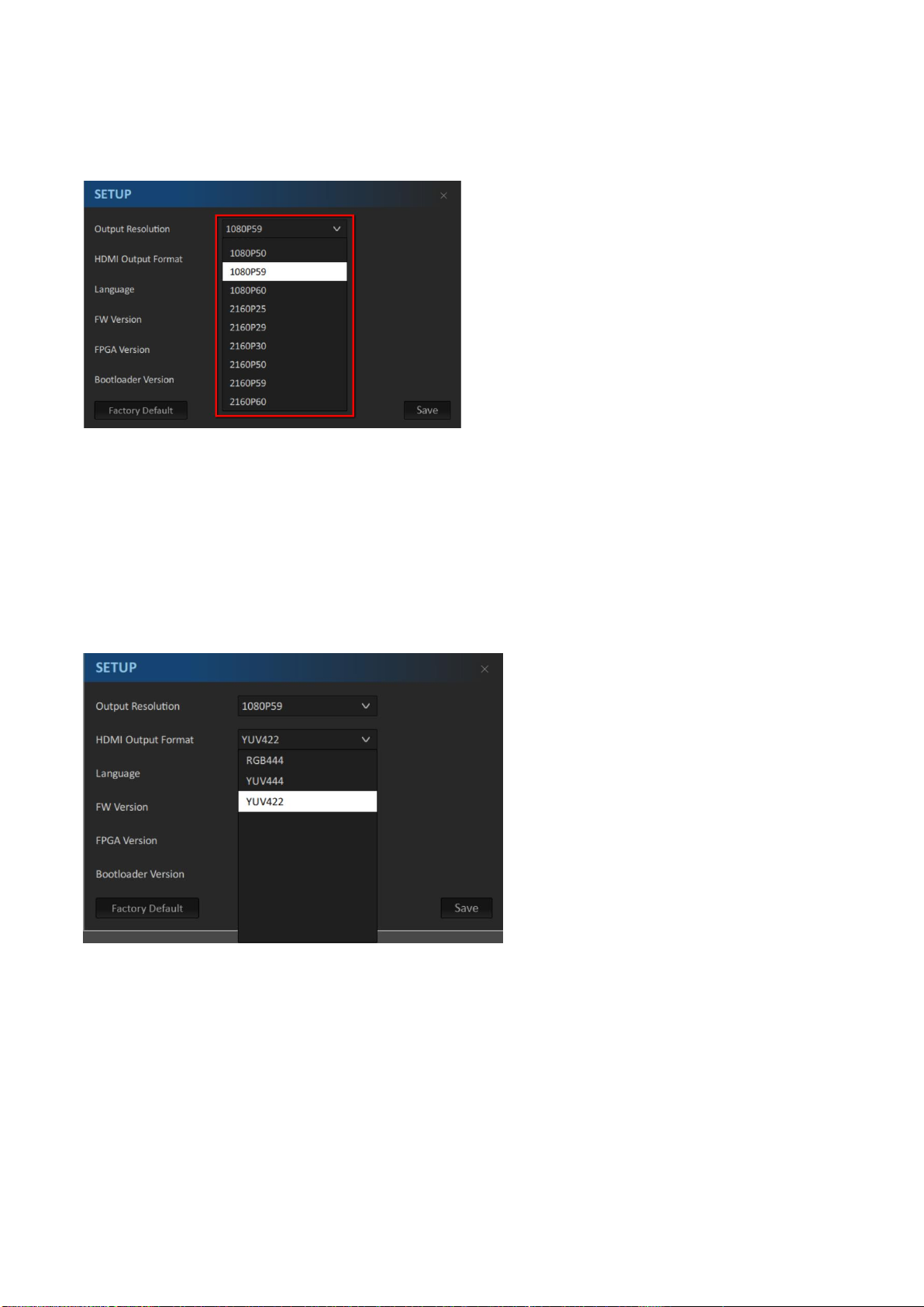
1. Output Resolution: After the DVK-400 is connected, please set the output resolution to be as
the same as the resolution of the foreground camera from this Output Resolution drop-down
menu.
Note:After the “Output Resolution” in the SETUP option is set, please press the “Save” button
for SETUP option and then those formats will become effective.
2. HDMI Output Format: This drop-down menu allows users to select many HDMI output formats
including RGB444, YUV444 and YUV442. After the “HDMI Output Format” is set, please remember
to press the “Save” button and then the new setting will take effect.
3. Language: The DVK-400 provides three Language options for users including English, Traditional
Chinese and Simplified Chinese. After the “Language” option is set, please remember to press the
“Save” button and then the new setting will take effect.
4. FW Version: Users can know the motherboard firmware version of the DVK-400 from this option.
5. FPGA Version: Users can know the FPGA Version of the DVK-400 from this option.
6. Bootloader Version: Users can know the Bootloader version of the DVK-400 from this option.
7. Factory Default: Users can press this button to set those settings to Factory Default values.
34
Page 35
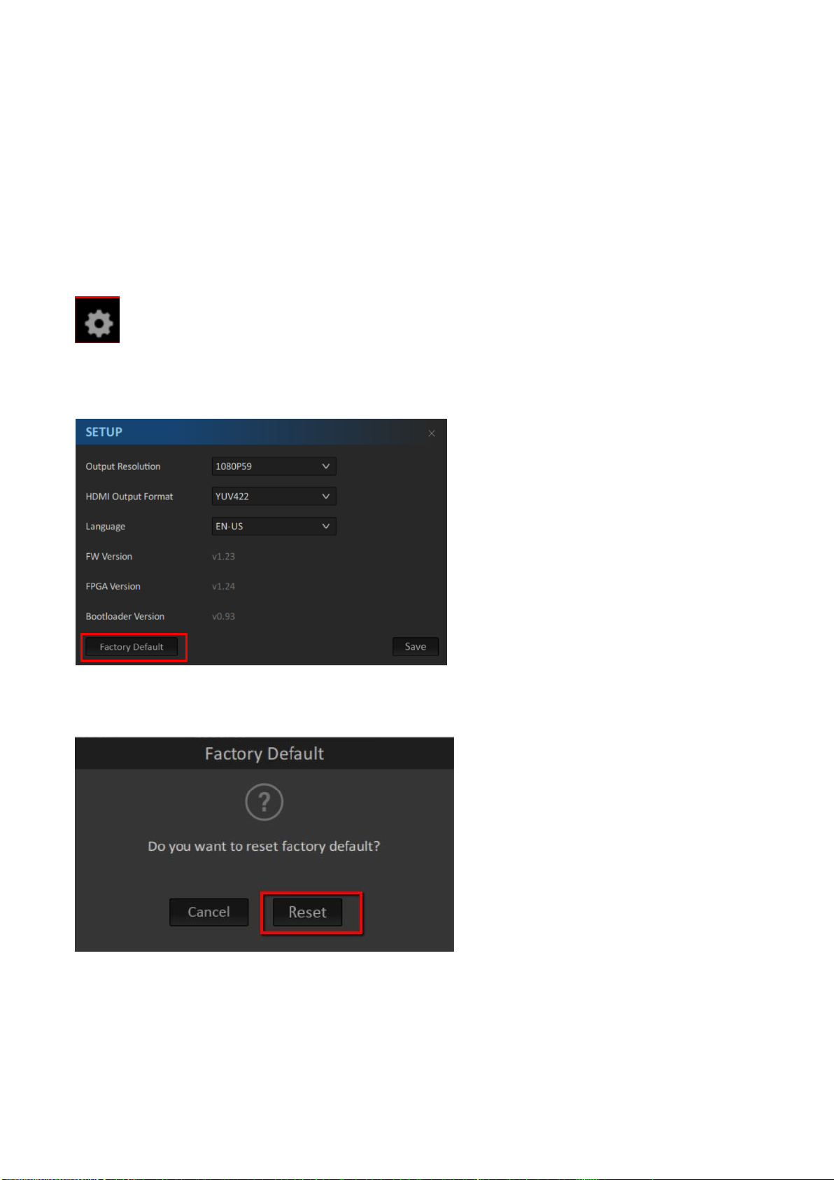
8. Save: This is the “Save” button. For the options including “Output Resolution”, “HDMI Output
Format” and “Language”, users need to press the “Save” button after each option is set for taking
effect those options.
5.4 How to Reset the DVK-400 to Factory Default Settings
Please follow following steps for reset the DVK-400 to Factory Default Settings.
1. Please press the “Setting” icon after the DVK-400 software is launched.
2. Please press the “Factory Default” button.
3. Please press the “Reset” button and then the DVK-400 will be reset to Factory Default Settings.
35
Page 36
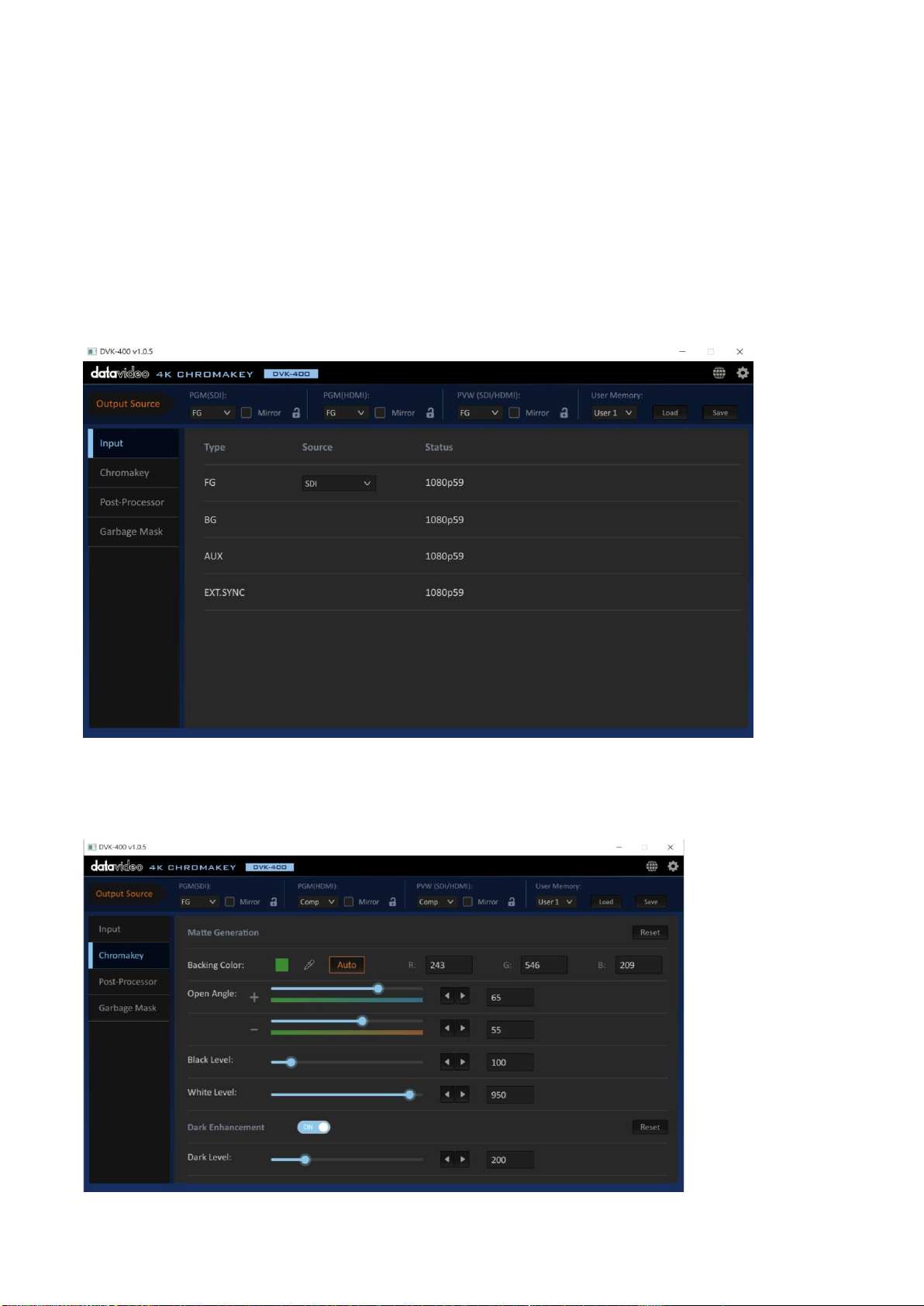
Chapter 6 How to Use the Chromakey Function for Video Chromakeying
Please follow following steps for Video Chromakeying by using the DVK-400 4K Chromakey.
1. Please make sure that the DVK-400 is connected successfully according to instructions in
previous chapter. Moreover, please make sure that all network related settings are set
successfully.
2. Please launch the DVK-400 control software.
3. Please click the “Chromakey” option.
36
Page 37
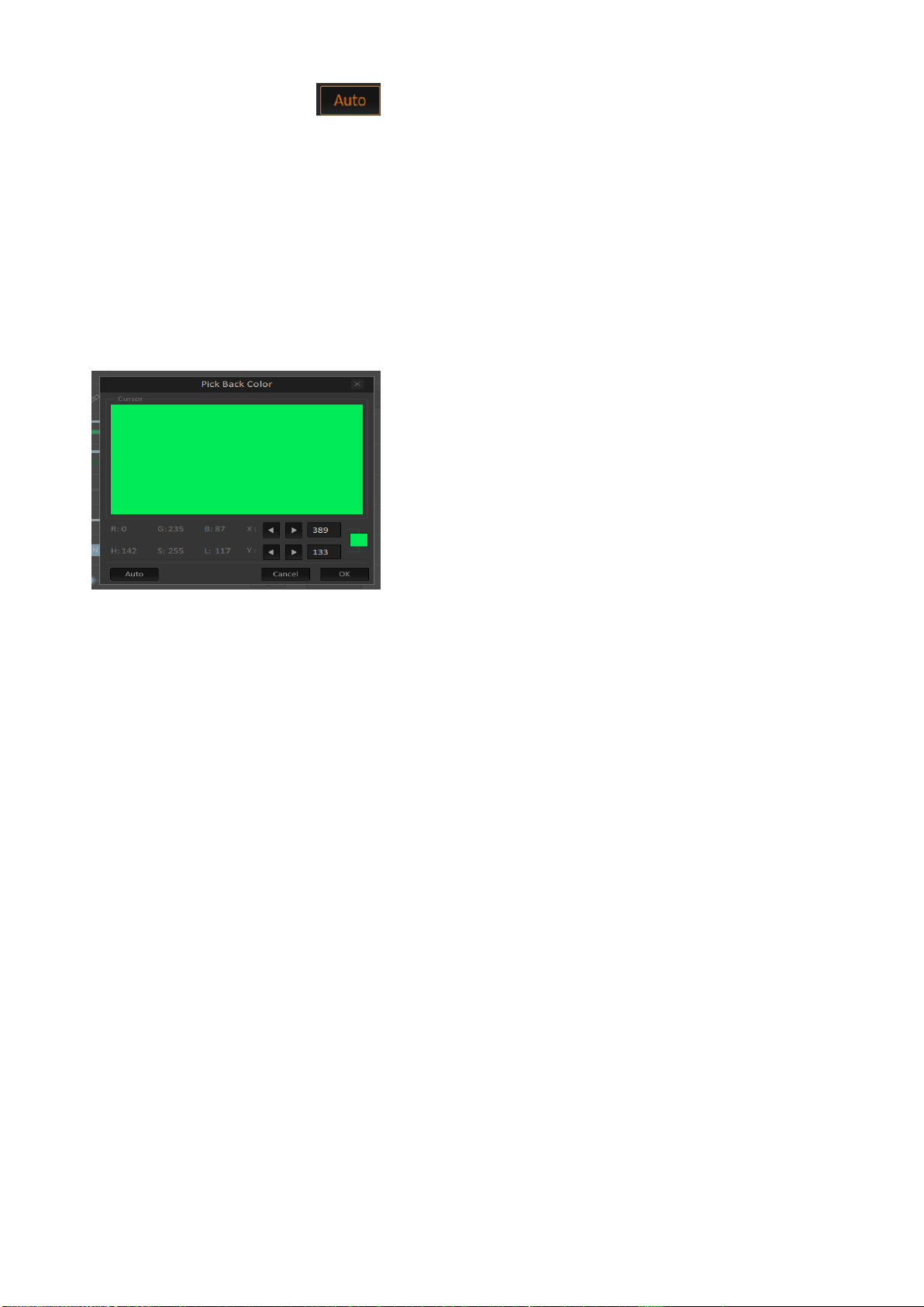
4. Please press the “Auto” icon in the “Backing Color” option for Auto Chromakeying.
The PWM OUT screen will be switched to the Foreground screen temporarily and there is a “+”
icon that will be shown and moved for 2 seconds for auto color sampling. After the screen color is
calculated automatically, all parameters in the Chromakey page will be reset to factory default
values and the video chromakeying will be done automatically.
5. There is a “Pick Back Color” background color sampling window that will be shown. Moreover,
there is a “+” icon that will be shown when the mouse is moved. At the same time, users can see
the movement of the “+” icon from the PGM OUT screen. Please move the “+” icon to the area of
your desired reference color and then please click the mouse once. After that, please click the
“OK” button and then the background color will be calculated automatically.
6. The video Chromakey procedure is finished until this step. If users are not satisfied about the
outcome of the Auto Chromakey, please fine-tuning a variety of control parameters in the
software. There are some rules of the fine-tuning which are shown as following points.
Increase the Black Level: This can help users to eliminate the unevenly lit screen.
Decrease the Black Level: This can help users to make the object which is affected by the
screen reflection to become solid.
Increase the Dark Level: This can help users to make the dark object or the black hair to
appear.
Increase the Bright Level: This can help users to make the bright object or glass to appear.
Increase the Shadow Level: This can help users to make shadows or the end of the black hair
to appear.
Increase the Spill Suppression: This can help to make the skin tone natural.
Adjust the Edge Brightness: This can help users to make the edge of the object or the
translucent brightness to match the background picture naturally.
37
Page 38
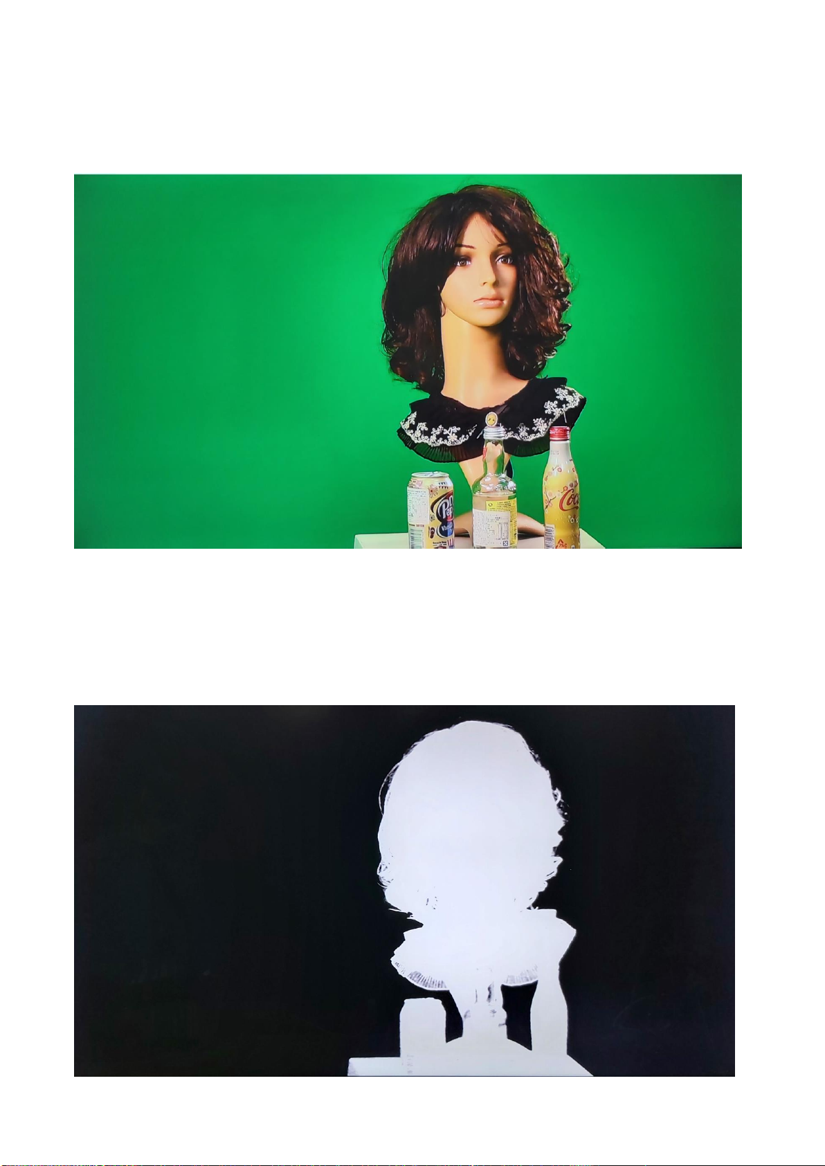
6.1 Example for Video Chromakeying by the DVK-400
At first, when the video is not chromakeyed, the background green mat is shown in green
which is shown as following diagram.
After the Auto Chromakey is done according to previous procedures, the screen will be
shown as following diagram. The area which is shown in black is the chromakey area for the
original green mat. The area which is shown in white is the solid area that will be kept after
the Auto Chromakey is done.
38
Page 39
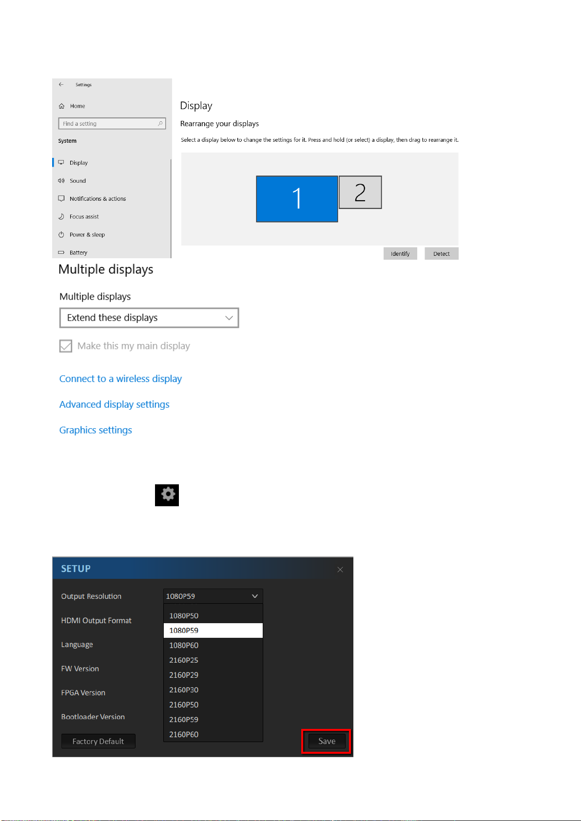
After that, please set your Monitor 1 as “Extend these displays”
Please press the button within the DVK-400 software to set the resolution of your
monitor 2 to be the same as the resolution of the foreground camera. After that, please press
the “Save” button.
39
Page 40
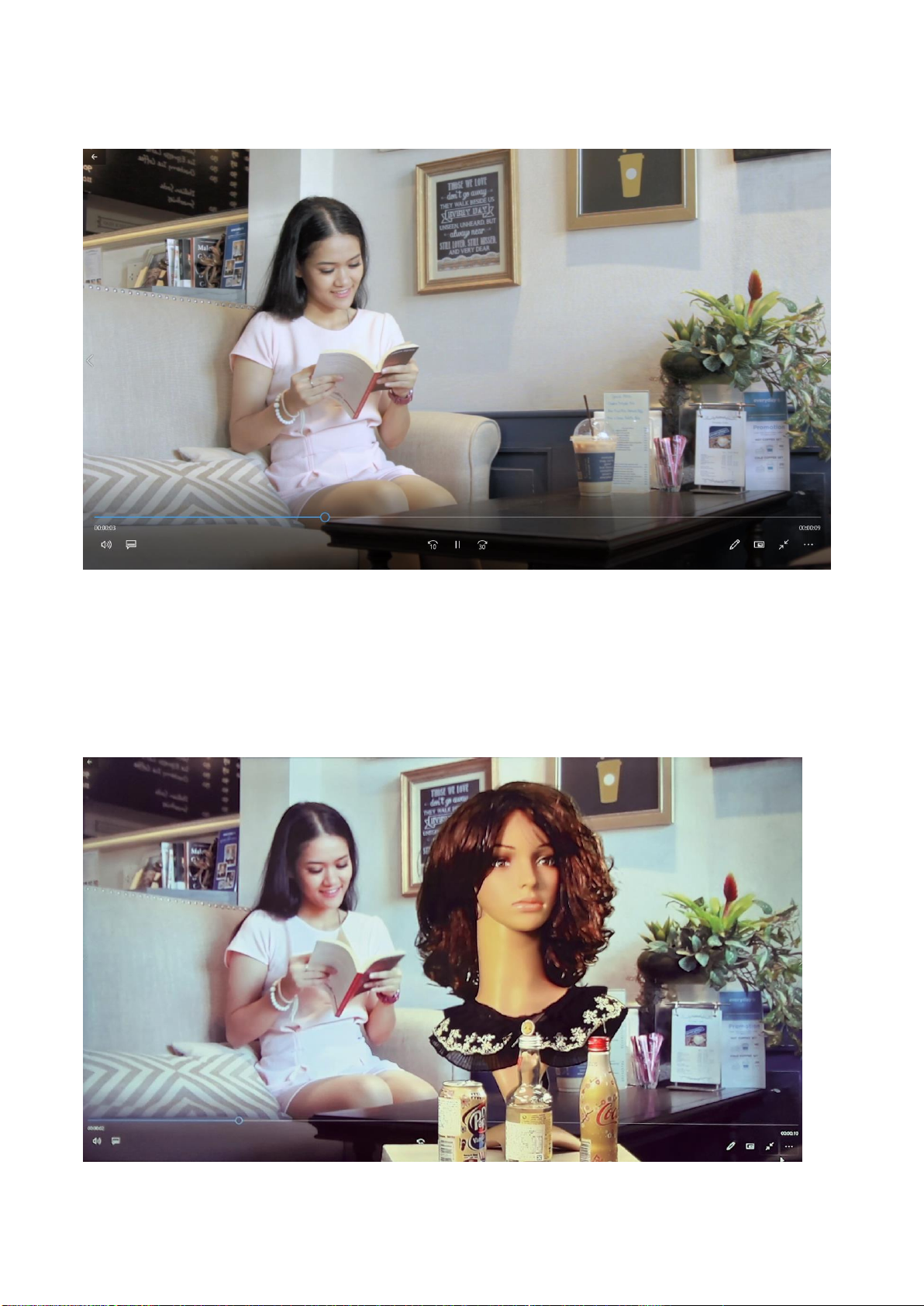
Please prepare the background video material in advance.
Please play the prepared background video and then please drag this video to the external
connected extended monitor. After that, the final chromakey outcome will be shown as
following diagram.
40
Page 41
Chapter 7. Firmware Update
Please follow following steps for updating the DVK-400 firmware.
1. Please download the latest DVK-400 firmware from the Datavideo official website
www.datavideo.com
2. Please prepare a USB thumb drive and then please unzip the downloaded firmware file to the
root directory of the USB thumb drive. Please make sure that the USB thumb drive must be
formatted to FAT16 or FAT32 format in advance.
3. Please unzip the downloaded firmware file to the root directory of the USB thumb drive and
then you can see that there are two files including DVK400FW.bin & DVK400FP.bin.
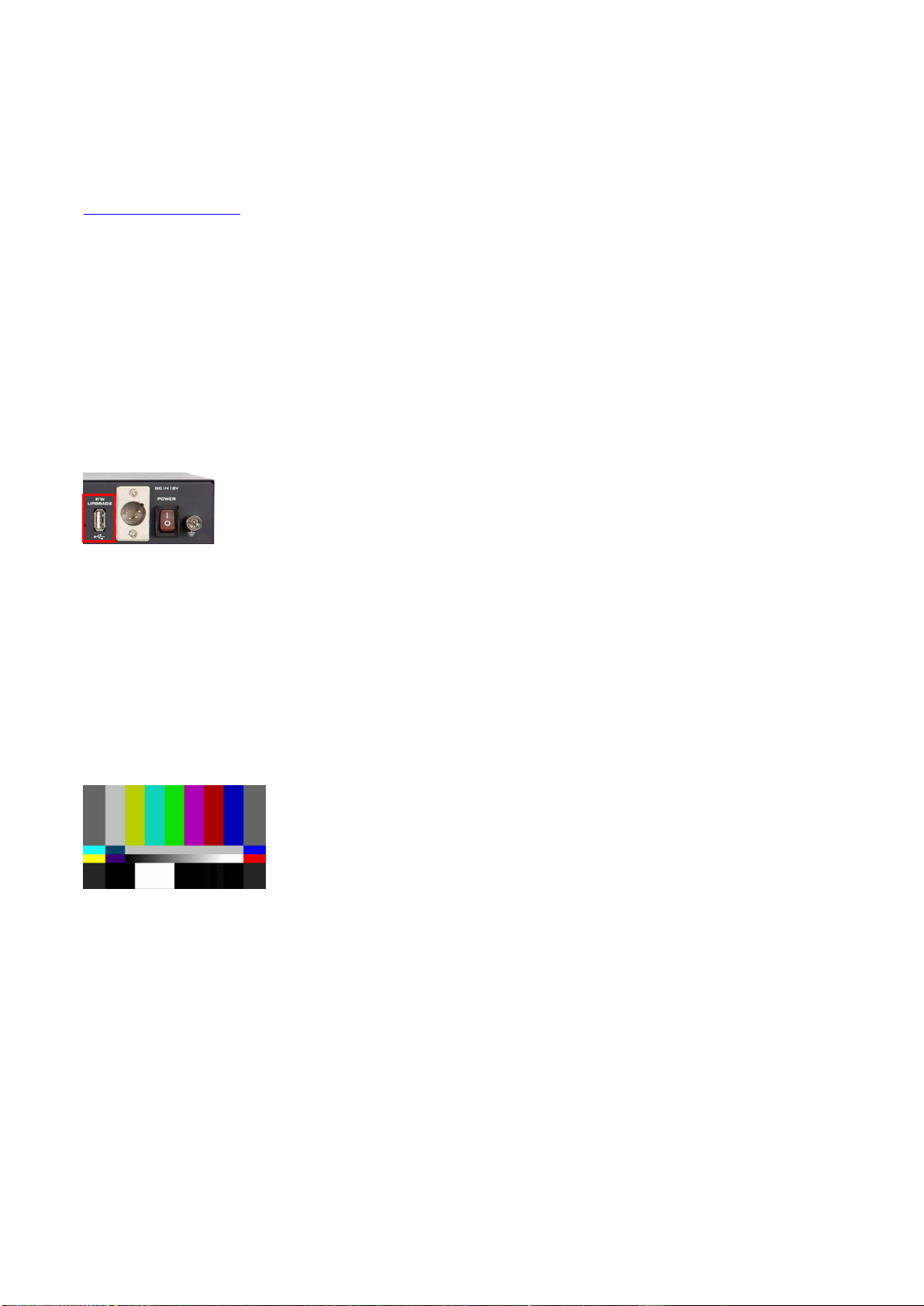
4. Please insert the USB thumb drive into the FW UPGRADE interface which is located on the rear
panel of the DVK-400.
5. Please connect any SDI OUT or HDMI OUT to an external connected monitor and then please
turn on the power of the DVK-400. After that, the firmware upgrading of the DVK-400 will be
started automatically. It will cost for about 1 minutes and there is no picture that will be shown on
the screen. If there is any LED indictor on the USB thumb drive, the LED will be blinking.
6. After the firmware update process is done, all of the HDMI or SDI output interfaces will output
the 1080p 59.94 color bar which is shown as following diagram. When the color bar is shown, it
means that the firmware update procedure is done and the USB thumb drive can be removed.
Note: If the firmware update procedure is failed, there is no output screen for about 1 minutes.
Please connect your notebook PC to the DVK-400 by the PC DVK-400 App (by RS-232 or DVIP
interface). After the connection is established, the color bar will disappear and the resolution will
go back to the original resolution. Please check whether the Firmware, FPGA and Bootloader
versions are updated correctly or not through the SETUP option.
41
Page 42
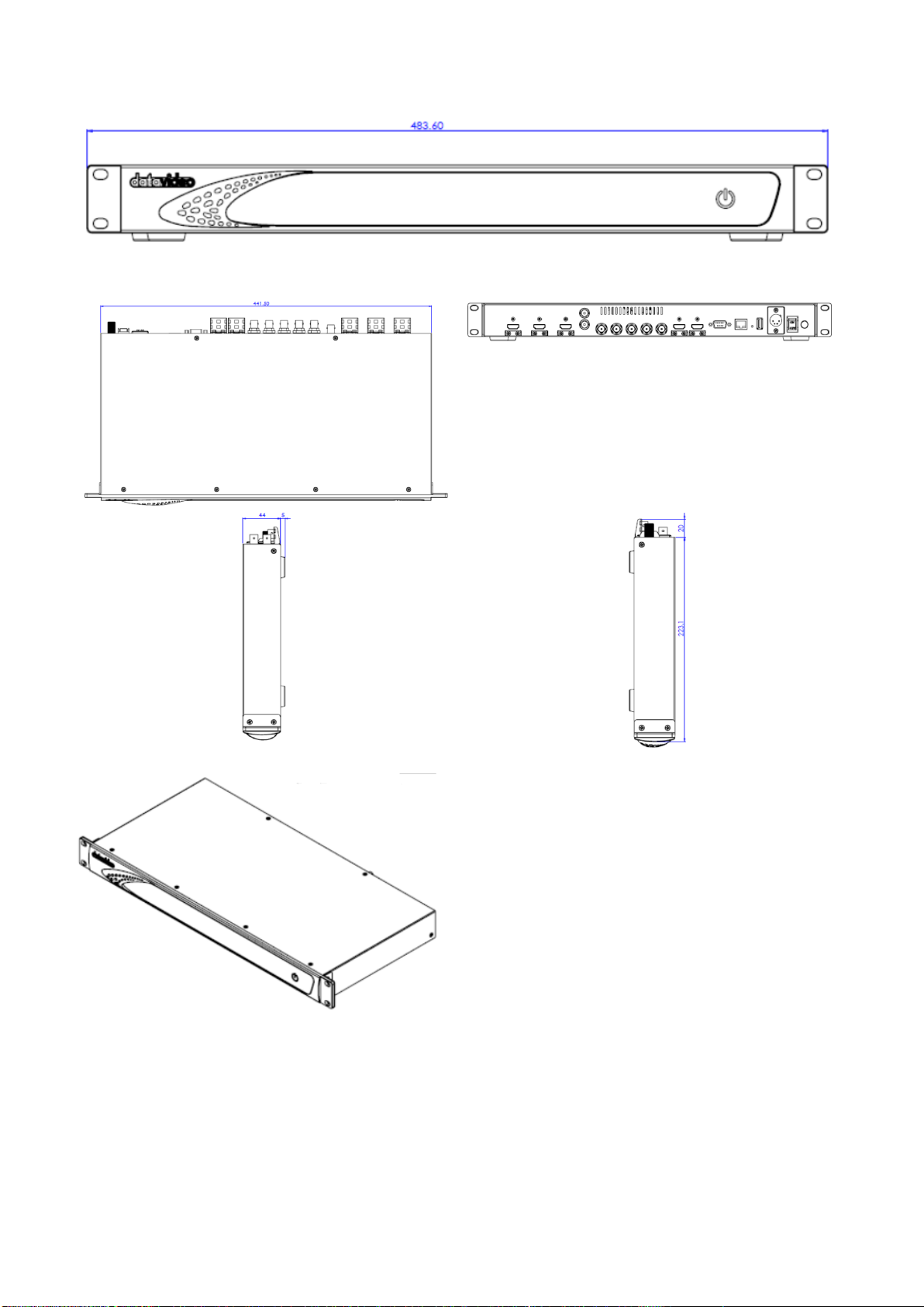
Chapter 8. Dimensions
Unit:mm
42
Page 43

Chapter 9 Frequently-Asked Questions
NO.
Problems
Solutions
1
How to restore the factory default IP
address of the DVK-400?
When the DVK-400 is connected to the
notebook PC directly by the static IP, if the
IP address can not be scanned, it is possible
that this DVK-400 was set in DHCP mode.
To solve this issue, please press the IP
RESET hole which is located on the rear
panel of the DVK-400 and then please turn
off and turn on the power of the DVK-400.
After the IP RESET hole is pressed for about
5 seconds, please release it. And then the
IP address of the DVK-400 will be restored
to the factory default static IP address
192.1 68.100.120. At this time, users can
scan the IP address for further connection.
2
Why sometimes the FG Status in the
Input column of the DVK-400 App
can not be recognized and what is
shown is “None”?
Please make sure that the DVK-400 is
connected correctly. If users switch to
different output source and there is no
change for the output, it means that there
is no connection between the DVK-400 and
the DVK-400 App. Please reconnect the
DVK-400 and the DVK-400 App again to
solve this issue.
If the connection is established correctly,
please make sure that the SDI or HDMI
setting is the same as the physical
connection and then the correct status can
be shown.
3
Why users press the icon to
sample the screen color of the FG,
however, the sampling screen can
not be shown on the PGM OUT?
It is recommended to connect to PVW OUT
when operating the DVK-400 and it will
switch to foreground automatically and the
cursor (+) will be shown. If users connect to
PGM OUT, this function can not be used.
This section describes problems that you may encounter while using the TVS-3000. If you
have questions, please refer to related sections and follow all the suggested solutions. If
problem still exists, please contact your distributor or the service center.
43
Page 44
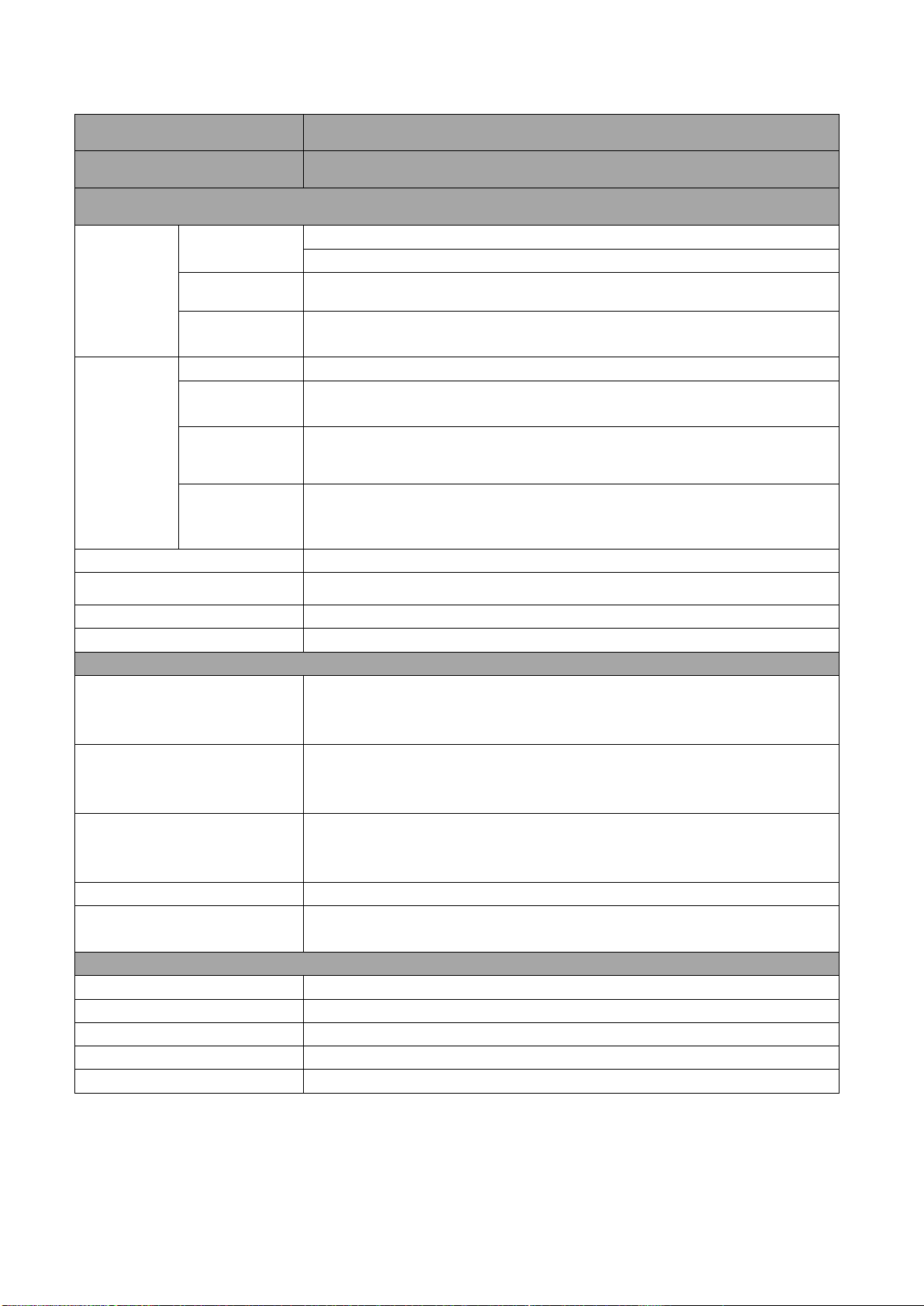
Chapter 10. Specifications
Model Name
DVK-400
Product Name
4K Chromakey
Interface
Inputs
Foreground
Camera
1 x 12G/3G-SDI
1 x HDMI 2.0
Background
Camera
1 x HDMI 2.0
AUX Input
1 x HDMI 1.4
(Used to input the Lumakey overlay or the external matte)
Outputs
Video Camera
1 x 12G/3G-SDI Camera loop out
Video PGM
Output
2 x 12G/3G-SDI
1 x HDMI 2.0
PVW Output
1 x 12G/3G-SDI
PGM
Mirroring,PFG,
Matte, Input
1 x HDMI 2.0
Sync Reference Signal
Input & Loop Output (Tri-Sync or Black Burst)
Control Ways
Ethernet,RS-232
Firmware Update
By USB
Power
DC IN 7~15V
Standard
Foreground Camera Video
Input Format
3840x2160p60/59.94/50/30/29.97/25
1080p 60/59.94/50/30/29.97/25
1080i 60/59.94/50
Background Video Input
Format
3840x2160p60/59.94/50/30/29.97/25
1080p 60/59.94/50/30/29.97/25
1080i 60/59.94/50
Video Output Format
3840x2160p60/59.94/50/30/29.97/25
1080p 60/59.94/50/30/29.97/25
1080i 60/59.94/50
Video Process
4:4:4 10bit
Color Space
SDI: YUV 4:2:2
HDMI: RGB 4:4:4 or YVU 4:4:4/YVU 4:2:2
General
Operating Temp.
0°C to 40°C (32°F to 104°F)
Storage Temp.
-20°C to 60°C (-4°F to 140°F)
Humidity
10% to 80% (Non-condensing)
Dimensions(mm)
483.6 x 242.8 x 44
Weight
2.7 Kg
44
Page 45

Note
45
Page 46

Note
46
Page 47

Note
47
Page 48
Mar.-31.2020
Version E1
Datavideo Technologies Co., Ltd. All rights reserved 2020
https://www.datavideo.com/product/DVK-400
 Loading...