

Page 1
XECOM (1) XEV90C
XEV90C
June 2000
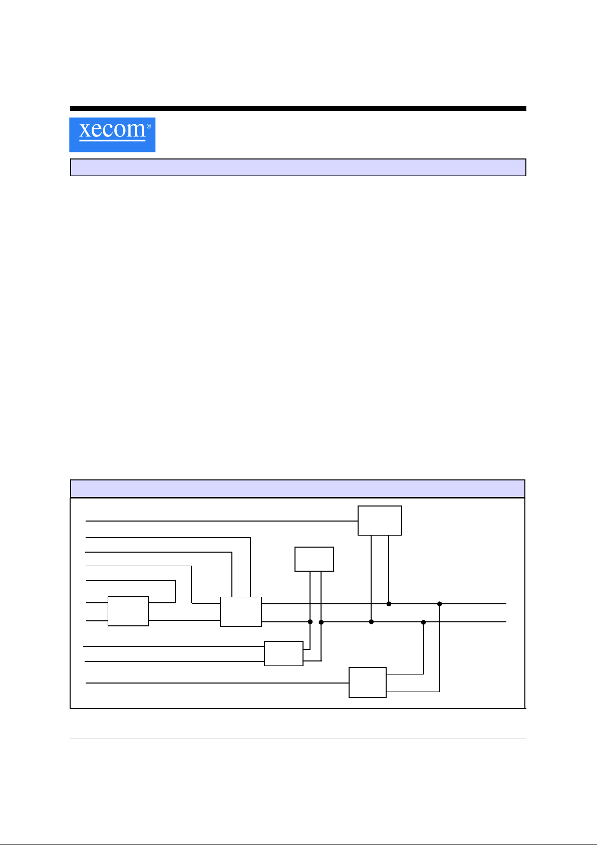
Figure 1: XEV90C BLOCK DIAGRAM
Line
Transformer
Line Current
Holding
Circuit
Hookswitch
Ring
Detector
T1
T2
OH(+)
Tip
Ring
Low
Impedance
Dialing
MUTE(-)
Description
Xecom’s XEV90C is a complete, multi-national DAA
integrated into a compact PLCC package. The XEV90C
supports analog data transfer to 56 KBPS and complies
with both FCC Part 68 Rules and the Pan-European
CTR21 specifications. The modified 68-Pin PLCC
package permits automated, high-volume assembly.
The XEV90C does not sacrifice performance for small
size and surface-mount convenience. The heart of the
XEV90C is a proprietary, low profile, low distortion
transformer. This wide bandwidth, low distortion device
provides the clear signal path required for 56 KBPS
analog data transfer.
The XEV90C is a complete telephone line interface. It
includes the telephone line transformer, line current
holding circuit, Caller ID Passthrough circuit,
hookswitch and ring indicator with line connect detect.
The XEV90C replaces the dozens of components found
in discrete and transformerless DAA designs.
Features
* Package: Thick 68-Pin PLCC (only 18 pins used)
dimensions 0.952 inches by 0.952 inches by 0.290
inches high
* Meets Total Harmonic Distortion requirements for
reliable 56 Kbps modems (-85 dB typical)
* Integrated Low-Distortion T elephone Line
Transformer
* Integrated Ring Detect with Line Connect Detect
capability
* Integrated Caller ID Passthrough Circuit
* Operates on a single Power Supply of +5 Volts
* Solid-State Hookswitch Control with active high
and active low inputs
* FCC Part 68 and CTR21 Compliant;
* Extended Temperature Range available, order part
number XEV90C-ITR;
OH(-)
RI(-)
DC2
DC1
Caller ID
Bypass
CAP1
CAP2
PLCC Packaged DAA for Europe and North America
Page 2
XECOM (2) XEV90C
Figure 2: XEV90C Pin Configuration
1
2
3
4
5
6
7
8
9
18
17
16
15
14
13
12
11
10
RI(-)
N/C
OH(+)
T1
T2
/Mute
OH(-)
VCC
Gnd
CAP1
Ring
Tip
N/C
N/C
CAP2
N/C
DC1
DC2
XEV90C
(top)
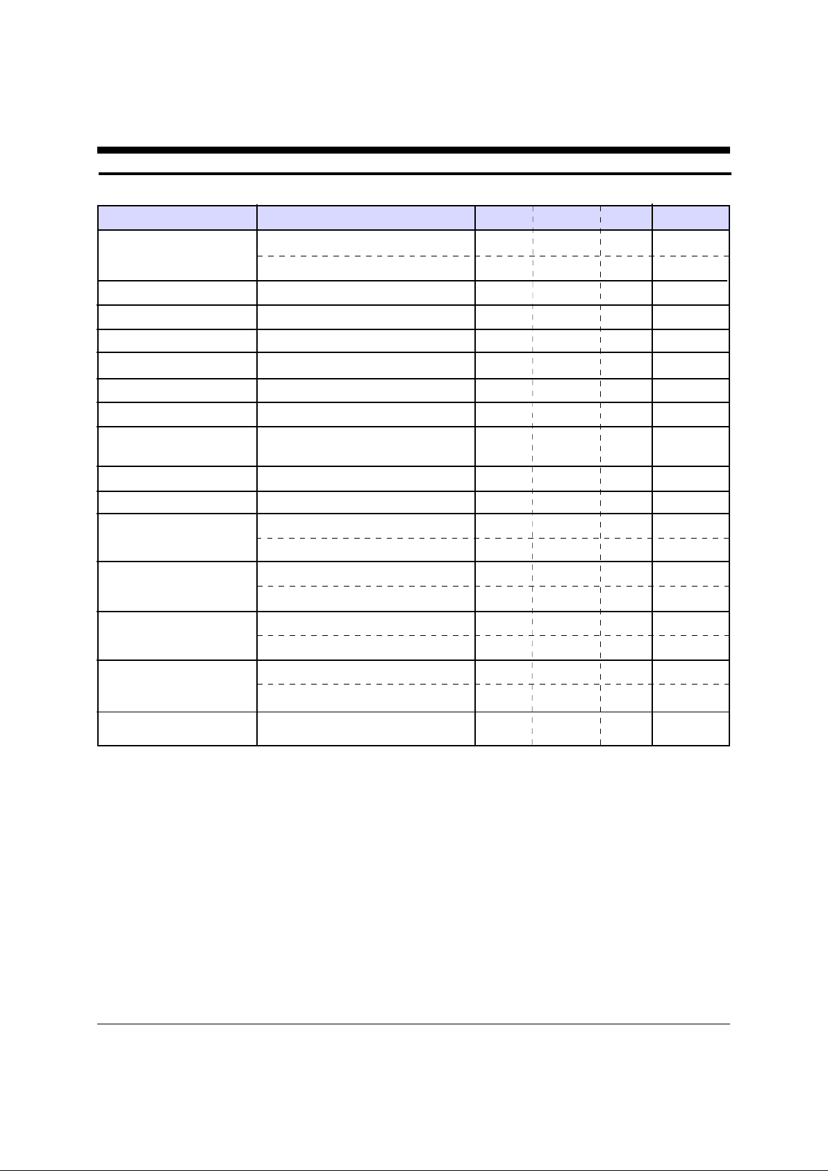
XEV90C Pin Descriptions
PIN NAME DESCRIPTION
1 CAP1 CAP1 provides a connection point for the external blocking capacitor on the XEV90C. Two
forty microfarad capacitors must be placed between the CAP1 and CAP2 pins for 56 KBPS
performance. Twenty microfarad capacitors can be used for lower data rate applications.
These polarized capacitors must be placed back-to-back to block line battery voltage of either
polarity. These capacitors must be rated at 50 volts for CTR21 applications and 10 volts if
CTR21 compliance is not required.
A 5 milliHenry inductor may be placed in series with the blocking capacitors to compensate for
the German billing tone filter. This filter is not addressed in CTR21 but is recommended for
applications destined for Germany to prevent interference with communications.
2 Ring Along with the Tip signal, Ring provides the connection to the telephone line. FCC Part 68
Rules require a 1500 volt isolation barrier between the telephone line and all other circuits. This
isolation must be preserved throughout the system.
The telephone company places a DC “Battery” voltage across Tip and Ring on all public switched
telephone lines. The XEV90C will operate regardless of the polarity of this “Battery” voltage.
The “Battery” voltage drives up to 100 milliamps of DC loop current.
UL1950 requires minimum creepage and clearances distances be maintained between the Tip
and Ring traces and all other circuits. Clearance is the shortest distance between conductive
circuits; creepage is the distance between conductive surfaces along the surface.
3 Tip Along with the Ring signal, Tip provides the connection to the telephone line. FCC Part 68
Rules require a 1500 volt isolation barrier between the telephone line and all other circuits.
This isolation must be preserved throughout the system.
4 - 5 No Connection
6 CAP2 CAP2 provides a connection point for the external blocking capacitor on the XEV90C. Two
forty microfarad capacitors must be placed between the CAP1 and CAP2 pins for 56 KBPS
performance. T wenty micro-farad capacitors can be used to meet lower data rate applications.
These polarized capacitors must be placed back-to-back to block line battery voltage of either
polarity.
Page 3

XECOM (3) XEV90C
7 No Connection
8 DC1 DC1 and DC2 control the performance of the loop current holding circuit. A jumper between
DC1 and DC2 limits the DC loop current to 60 milliamps as required for CTR21. An open
circuit between DC1 and DC2 allows loop currents up to 100 milliamps as required for North
America and Japan. A resistor may be placed between DC1 and DC2 to adjust DC off-hook
impedance to meet unique country requirements.
9: DC2 DC1 and DC2 control the performance of the loop current holding circuit. A jumper between
DC1 and DC2 limits the DC loop current to 60 milliamps as required CTR21. An open circuit
between DC1 and DC2 allows loop currents up to 100 milliamps.
10 Ground Ground provides the reference voltage for all host interface signals.
11 VCC VCC provides operating power to the XEV90C. VCC must equal five volts plus or minus 10
percent.
12 OH(-) OH(-) controls the switch-hook within the XEV90C with an active low input. If the user wishes
to use an active high device to drive the switch-hook, Pin 16 provides the active high switch-
hook control. Activating OH(-) closes the internal switch-hook and seizes the local telephone
line. OH(+) must remain open when OH(-) is in use.
13 Mute(-) Mute(-) provides an active low input for low impedance pulse dialing or for meeting the
minimum transitional impedance required by CTR21. Presenting a low impedance while pulse
dialing is a requirement of several European countries including, Germany, France and Italy.
CTR21 does not regulate pulse dialing. European pulse dialing requirements continue to be set
by the individual countries.
14 T2 T2 in conjunction with T1 provides the differential input/output for the analog signal.
15 T1 T1 in conjunction with T2 provides the differential input/output for the analog signal.
16 OH(+) OH(+) controls the switch-hook within the XEV90C with an active high input. If the user
wishes to use an active low device to drive the switch-hook, Pin 12 provides the active low
switch-hook control. Activating OH(+) closes the internal switch-hook and seizes the local tele-
phone line. OH(-) must remain open when (OH+) is in use.
17 No connection
18 RI(-) RI(-) indicates the presence of an incoming ring (Ring Indication) or a drop in the Battery
Voltage on the local telephone line (Connect Detection). RI(-) is an active low signal. RI(-)
provides a square wave representation of the ring signal present on the telephone line. This
permits the host to intelligently monitor the local telephone line.
RI(-) also communicates the availability of the local telephone line with the Connect Detect
Feature. When the Battery Voltage on T ip and Ring drops below twenty volts, RI(-) switches to
high level to indicate the local telephone line is not available for use.
XEV90C Pin Descriptions (continued)
PIN NAME DESCRIPTION
Page 4
XECOM (4) XEV90C
XEV90C Electrical Specifications (Vcc=+5v ±10%, Ta=0 to 70 deg C)
Power Supply Current Off-hook 10 mA
On-hook 0.5 mA
Transmit Insertion loss 600 Ohm Impedance, 1800 Hz 2 3.5 5.0 dB
Receive Insertion loss 600 Ohm Impedance, 1800 Hz 3.5 5.0 6.5 dB
Caller ID Insertion Loss Hookswitch Open 10.0 11.5 13 dB
Line Matching Impedance Input to T1 and T2 300 340 37 0 ohms
Line Impedance 370 ohm matching impedance resistor 540 600 660 ohms
Total Harmonic Distortion 600 Ohm Impedance, 100 to 4000 Hz -80 -85 dB
Ring Detect Sensitivity Min. AC voltage between Tip & 20 150 Vrms
Ring Type B ringer
Ring Frequencies Detected 16 68 Hz
RI Output Voltage Ring signal present, Active low 0.2 0.5 Volts
Hook-Switch Control ON: (off-hook) 0.2 0.5 Volts
Voltage (active high) OFF: (on-hook) 2.0 3.0 Volts
Hook-Switch Control ON: (off-hook) 2.0 3.0 Volts
Voltage (active low) OFF: (on-hook) 0.2 0.5 Volts
Hook-Switch Control ON: (off-hook) 5 10 milliamps
Current OFF: (on-hook) 5 microamps
Loop Current No Connection from DC1 to DC2 0 10 0 mA
(current draw from line) DC1 shorted to DC2 0 60
DC On-Hook Impedance Hookswitch Open 10 MOhms
Parameter Conditions Min Typ Max Units
Page 5

XECOM (5) XEV90C
XEV90C Mechanical Specifications
A
A1
D3
a
h x 45 degrees
(3 Places)
D2
b
e
D1
D1
D
Index Corner
J x 45 degrees
Inches Millimeters
Dim Min Ref Max Min Ref Max
A 0.280 0.300 7.11 7.62
A1 0.020 0.51
b 0.017 0.021 4.32 5.33
D 0.985 0.995 25.0 25.27
D1 0.952 24.18
D2 0.800 20.32
D3 0.910 0.930 23.1 23.62
e 0.100 2.54
h 0.010 0.25
J 0.045 1.15
a45
O
45
O
coplanarity 0.004 0.10
(top)
10
1
9
(bottom)
XEV90C ABSOLUTE MAXIMUM RATINGS
Storage T emperature -25O C to +85O C
Operating T emperature Range * 0O C to +70O C
* The XEV90C can be ordered with an Operating T emperature of -40O C to +85O C at extra cost.
Order XEV90C-ITR to specify Industrial T emperature Range (ITR).
Page 6

XECOM (6) XEV90C
Slim-Link® PLCC Soldering Instructions
Because of its Hybrid construction, the XEV90C DAA is subject to damage if over-exposed to heat during solder
reflow operations. Following the soldering instructions below will ensure that the process of soldering the module to
the board does not damage the DAA.
Maximum T emperature 220O C
Maximum Time at 220O C 20 Seconds
Maximum Time above Eutectic (180O C) 90 Seconds
Maximum Preheat Dwell Time 180 Seconds
Maximum Recommended Solder Temperature Pr ofile
220O C
180O C
150O C
-20 sec-
--------------------------------180 sec max --------------------- max
----- 90 sec max -----
Notes:
Because of their large black bodies, Xecom’ s XEV90C DAA modules must not be exposed to direct Infrared (IR)
heating. If your process includes direct IR heating, you must shield the PLCC DAA module from the infrared rays.
Xecom’s XEV90C DAA modules should be exposed to no more than one reflow cycle.
Page 7

XECOM (7) XEV90C
XEV90C Typical Connection Diagram
RJ11
1 CAP1 RI(+) 18
2 Ring 1 7
3 Tip OH(+) 16
4 T1 15
5 T2 14
6 CAP2 /Mute 13
7 OH(-) 12
8 DC1 VCC 11
9 DC2 Gnd 10
L1
XEV90C
J1
RingD
TXA1
Rin
VC
TXA2
+5V
FB1
FB2
Teccor P3100
340
2 K
10K
27 K
RC56ACL
-OH
C1
C2
MUTE
C3
C4
Recommended Componants
Billing Tone
Maximum Ferrite Beads Filter (Opt.)
Region Data Rate C1 & C2 FB1 & FB2 C3 & C4 L1 J1 S1
N. America 56K 470 pfd, 1.5KV TDK ACB2012L-120 40 ufd, 10V OUT OUT OUT
Europe 56K 470 pfd, 1.5KV TDK ACB2012L-120 40 ufd, 50V 5 mh IN OUT
Universal 5 6K 470 pfd, 1.5KV TDK ACB2012L-120 40 ufd, 50V 5 mh OUT IN
N. America 33.6K 470 pfd, 1.5KV TDK ACB2012L-120 20 ufd, 10V OUT OUT OUT
Europe 33.6K 470 pfd, 1.5KV TDK ACB2012L-120 20 ufd, 50V 5 mh IN OUT
Universal 33.6K 470 pfd, 1.5KV TDK ACB2012L-120 20 ufd, 50V 5 mh OUT IN
Notes:
1) C1, C2, FB1, and FB2 provide filtering to meet EMI restrictions. They may be omitted if your equipment meets the appropriate EMI standards without them.
2) Some countries including Germany use billing tones which can interfere with communciations. L1 blocks the tone from
reaching the receiving equipment. This filter is not required for certification but is recommended for applications to be used in
Germany to prevent compromises in performance.
3) In rare instances when the CTR21 current limiting circuit is active, the XEV90C may be required to dissipate more than 2
Watts from the flow of loop current. A Heat Sink is required to dissipate the resulting heat without endangering the device.
Xecom recommends an AAVID 3352 or equivalent heat sink for applications which support CTR21.
4) UL1950 requires minimum creepage and clearance distances to be maintained for telecommunications circuits. Clearance is
the straight-line distance between two conductive points. Creepage is the distance along the surface between two conductive
points. Consult UL1950 for the minimum creepage and clearance distances which apply to your equipment.
5) By adding an switch S1 in place of J1 it is possible to have a single DAA which is software selectable for European or North
American applications.
16
24
/CTR21
+5V
470
LH1540AT
S1
Page 8

XECOM (8) XEV90C
Application Notes
Dialing:
The public switched telephone network permits tone and rotary
(pulse) dialing. The XEV90C supports both types of dialing.
Tone dialing requires an external signal source to provide the
dialing tones. Rotary dialing is accomplished by pulsing the
OH or Mute line on the XEV90C.
Pulse Dialing: The XEV90C generates dialing pulses through
momentary closures of the switch-hook. Pulsing the MUTE
signal can also be used to generate dialing pules. Each digit is
represented as a series of pulses, one pulse for a one to ten
pulses for a zero. The pulse rate in normally ten pulses per
second. Some European countries require 20 pulses per second.
The dialing pulses are asymmetrical. Consult with the local
country regulations for the required duty cycle. An interdigit
delay of at least one hundred milliseconds separates the digits.
Tone Dialing: To tone dial the XEV90C seizes the line, OH
active. For each digit a unique DTMF, Dual Tone Multiple
Frequency, tone pair is placed across T1 and T2. The higher
frequency tone is always of greater magnitude than the lower
frequency tone. Transmit the tones for a minimum of 70
milliseconds, and leave a minimum of 70 milliseconds between
digits.
The table below shows the correct DTMF signal frequencies for
each digit.
Digit Lower Tone Upper Tone
1 697 1209
2 697 1336
3 697 1477
4 770 1209
5 770 1336
6 770 1477
7 852 1209
8 852 1336
9 852 1477
0 941 1336
* 941 1209
# 941 1477
Signal Levels:
FCC Part 68 Rules set the allowable signal level
in the US for all signals placed on the telephone line other than
live voice. Other countries have similar regulations. Signal
levels are measured in dBm. Zero dBm is 1 milliwatt through a
600 ohm load.
Insertion Loss: There is some loss of signal power as the
information signal passes through the XEV90C. This "insertion" loss should be taken into account when placing signals
across T1 and T2 for transmission. The typical insertion loss of
the XEV90C is 3.5 dBm.
Total Harmonic Distortion:
Total Harmonic Distortion is the most common measure of the
signal path quality provided by the DAA. The primary sources
of distortion in the DAA are the Telephone Line Transformer
and the Line Current Holding Circuit, although board layout
and other factors can introduce distortion.
Total Harmonic Distortion varies with frequency. The voice
band provided by the telephone line is limited to less than 4000
Hz. 56KBPS modems require virtually all of this bandwidth for
signal transmission. Even if the Total Harmonic Distortion of a
device is very good in the center portion of the spectrum, signal
quality is compromised if distortion greatly increases at the
outer limits of the voice band.
Note: This chart represents the total harmonic distortion of the
complete DAA not just the telephone line transformer.
Distortion measurements of the transformer only will
show much lower distortion but do not account for
distortion from other sources.
50
55
60
65
70
75
80
85
90
50 100 200 500 1000 1500 2000 4000
Page 9

XECOM (9) XEV90C
XEV90C
2/4 Wire Conversion:
Full Duplex communications over a two-wire telephone line
requires that transmit and receive signal share the available
bandwidth. The two-to-four wire convertor separates these
signals at the host interface. Most modem analog front end
chips incorporate an internal 2/4 wire convertor making it
unnecessary to provide one in the DAA.
If you are using the XEV90C for an application other than a
modem, such as voice processing, or your modem analog front
end does not provide the 2/4 wire convertor, you will need to
provide a discrete 2/4 wire convertor. The schematic on this
page shows a simple 2/4 wire convertor circuit.
The performance of the 2/4wire convertor is measured by its
Transhybrid Loss. The Transhybrid Loss shows how much the
2/4 wire convertor attenuates the transmit signal on the received
data line. The circuit above provides a typical Transhybrid Loss
of 20 dB.
The Transhybrid Loss will vary with the quality of the
impedance match to the telephone line. Even when the
recommended value for the impedance matching resistor, R6,
is used variations from line to line alter the impedance match.
The value of R3 can be changed to improve the Transhybrid
Loss.
The 2/4 wire convertor also amplifies the transmit and receive
signals to compensate for the insertion loss of the DAA. This
circuit provides 6 dB gain of both the transmit and receive
signals. The values of R1 and R2 set the transmit gain. The
values of R4 and R5 set the receive gain.
2/4 Wire Convertor
R6
R2
R1
R3
R4
R5
4558
4558
10K
11.5K
40K
340 ohms
20K
T1
T2
Transmit
Receive
Page 10

XECOM (10) XEV90C
Telephone Line Connection Information
When developing a product to be connected to the telephone line, it is necessary to use a circuit known as a Data
Access Arrangement (DAA) approved by the appropriate governmental agency. In the US this agency is the Federal
Communications Commission (FCC), while in Canada it is Industry Canada (IC). In Europe the CTR21 standard
covers all countries in the European Union. These agencies test and approve the product to ensure that it meets their
specifications, thereby protecting the telephone system from damage and protecting the user from high voltage
transients (such as lightning strikes) which may come down the telephone line.
The XEV90C has been designed to meet all FCC Part 68 requirements for hazardous voltage, line impedance and
leakage current. If the system transmits data, synthesized voice, or DTMF tones on the telephone line, the user must
certify that the signals transmitted meet basic FCC requirements for maximum transmission levels, out of band energy
and billing delay. Full details may be obtained from the FCC under Part 68 of the FCC Rules and Regulations, or in
Title 47 of the Code of Federal Regulations, however the basic requirements are as follows:
1. Maximum Transmit Level
For the normal “permissive” (standard) telephone line, equipment which transmits data (such as a modem) must not
exceed a transmission level of -9 dBm.
2. Out of Band Energy
Data equipment must not transmit “out of band” energy on the telephone line which exceeds the following limits:
Frequency Range Max. Power
3995 Hz to 4005 Hz -27 dBm
4005 Hz to 12 kHz -20 dBm
12 kHz to 90 kHz -55 dBm
90 kHz to 270 kHz -55 dBm
270 kHz to 6 MHz -15 dBm
3. DTMF Transmission Level
If the system is capable of DTMF dialing, the maximum DTMF transmission level must be less than 0 dBm averaged
over a 3 second interval.
4. Billing Delay
A delay of 2 seconds or greater is required after the time the XEV90C is taken “off hook” and before any information
is transmitted. This is required to ensure that billing information may be exchanged between telephone company
central offices without interference.
OEM’s using the XEV90C must certify to the FCC that the final system meets the requirements of Part 68 which
include the criteria above as well as the high voltage protection provided by the XEV90C. This is generally
accomplished through an independent testing lab which tests the System and submits the proper paperwork to the FCC
for approval. Since the XEV90C already complies with FCC Part 68 rules, this is a relatively simple process.
Page 11

XECOM (11) XEV90C
Copyright, Xecom © 2000
While Xecom, Inc. has made every effort to ensure that the information presented here is accurate, Xecom will not
be liable for any damages arising from errors or omission of fact. Xecom reserves the right to modify specifications
and/or prices without notice. Product mentioned herein are used for identification purposes only and may be trademarks and/or registered trademarks of their respective companies.
Xecom
Incorporated
374 Turquoise Street, Milpitas, CA 95035
Ph:408-945 -6640 Fax:408 -942-1346
Email: info@xecom.com
Terms of Sale
Devices sold by XECOM are covered by the warranty provisions appearing in its Terms of Sale only. XECOM
makes no warranty, express, statutory, implied, or by description regarding the information set forth herein, or
regarding the freedom of the described devices from patent infringement. XECOM makes no warranty of
merchantability or fitness for any purposes. XECOM reserves the right to discontinue production and change
specifications and prices at any time and without notice. This product is intended for use in normal commercial
applications. Applications requiring extended temperature range, unusual environmental requirements, or high
reliability applications, such as military, medical life-support or life-sustaining equipment, are specifically not
recommended without additional processing and authorization by XECOM for such application.
Xecom assumes no responsibility for the use of any circuitry other than circuitry embodied in a Xecom product.
No other circuits, patents, or licenses are implied.
Life Support Policy
Xecom's products are not authorized for use as Critical Components in Life Support Devices or Systems.
Life Support Devices or Systems are devices or systems which, (a) are intended for surgical implant into the body,
or (b) support or sustain life, and whose failure to perform, when properly used in accordance with instructions provided in the labeling, can be reasonably expected to result in significant injury to the user.
A Critical Component is any component of a life support device or system whose failure to perform can be reasonably expected to cause failure of the life support device or system, or to affect its safety or effectiveness.
 Loading...