

Page 1
A Complete Send and Receive Fax & Data Modem
XE9624F & XE9624FS
10-03-95
Description
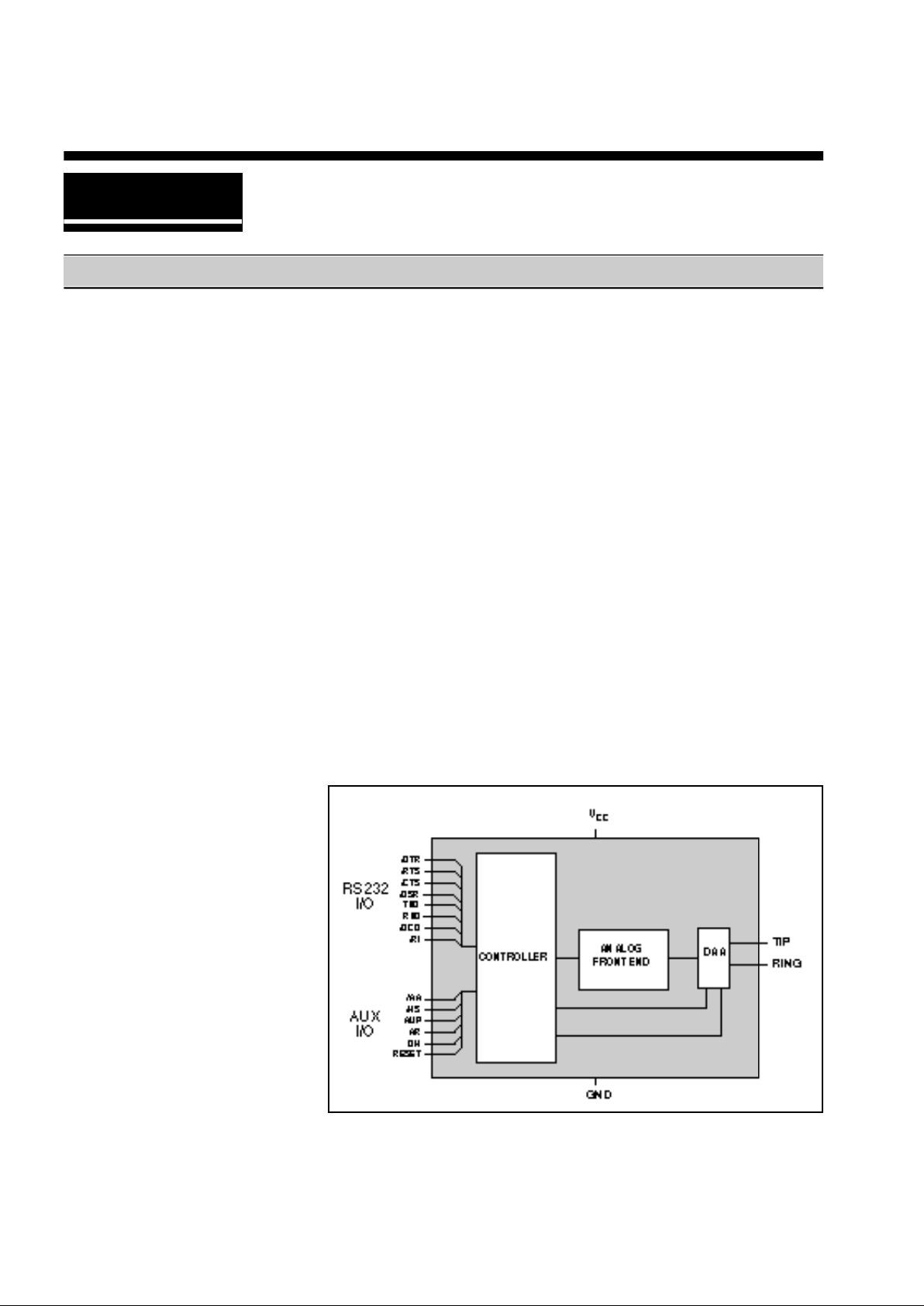
Xecom's XE9624F and XE9624FS include a
2400bps data modem, a Group III Send and
Receive fax modem and the telephone
interface in one compact component. Both
models include user transferable FCC Part
68 registration.
Xecom puts the XE9624F in our dual inline
package. The XE9624F is pin compatible
with other Xecom modems including the
XE2401, XE2496, and XE9624E.
The XE9624FS comes in a Single Inline
Package. The XE9624FS can be ordered
for either vertical (XE9624FS1) or horizontal
(XE9624FS2) mounting to optomize space
utilization.
Xecom designed the XE9624F
and XE9624FS specifically to
provide computer, notebook,
and industrial systems
manufacturers with a complete,
highly integrated, compact
solution for adding data and fax
communications.
Block Diagram
Features
• Data Rates: 2400, 1200 and 300 bps
• Send fax to 9600 bps
• Receive fax to 4800 bps
• Enhanced "AT" commands for modem
control and configuration.
• Class 1 commands for facsimile control.
• Single +5V supply
• Low power CMOS:
Operating: 200 mW (Typ.)
Sleep mode: 50 mW (Typ.)
• Dimensions;
XE9624F: 2.28" by 1.08" by 0.42"
• XE9624FS: 1.53" by 0.46" by 0.92"
xecom
Page 2
2/XECOM XE9624F/XE9624FS
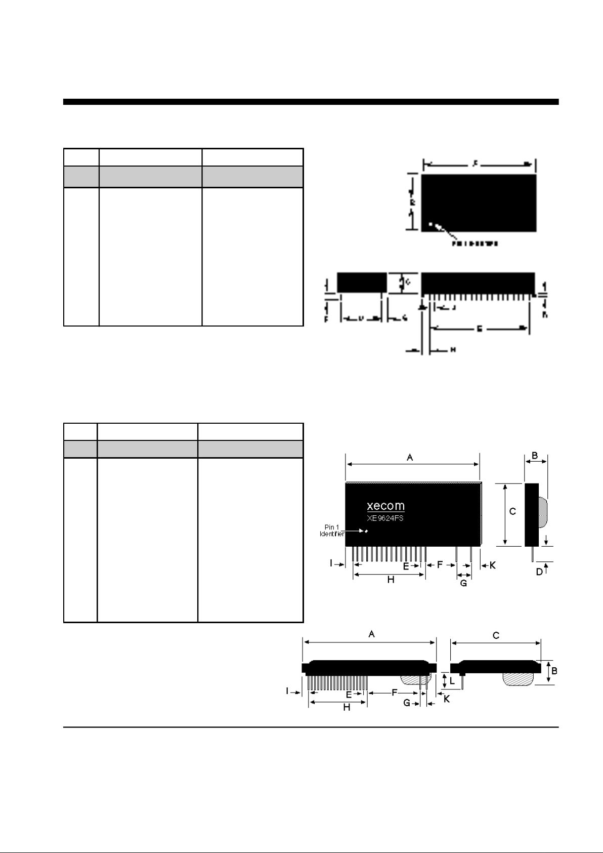
A 2.270 2.290 57.66 58.17
B 1.070 1.090 27.18 27.69
C 0.420 0.430 10.67 10.92
D 0.890 0.910 22.61 23.11
E 1.890 1.910 48.01 48.51
F 0.125 0.200 3.18 5.08
G 0.080 0.100 2.03 2.54
H 0.180 0.200 4.57 5.08
J 0.090 0.110 2.29 2.79
K 0.020 0.025 0.51 0.64
XE9624F Mechanical Specifications
Pins = 0.025 inch square pin
All pins tin-plated
INCHES METRIC(MM)
PIN MIN MAX MIN MAX
XE9624FS Mechanical Specifications
Pins = 0.018 inch diameter pin
All pins tin-plated
A 1.500 1.560 38.10 39.62
B 0.430 0.490 10.92 12.45
C 0.890 0.950 22.61 24.13
D 0.090 0.140 2.23 3.56
E 0.045 0.055 1.14 1.40
F 0.340 0.360 8.64 9.14
G 0.140 0.160 3.56 4.06
H 0.790 0.810 20.07 20.57
I 0.050 0.110 1.27 2.79
K 0.200 0.260 5.08 6.60
L 0.420 0.480 10.67 12.19
INCHES METRIC(MM)
PIN MIN MAX MIN MAX
XE9624FS1
XE9624FS2
Page 3

XE9624F/XE9624FS XECOM\3
Pin Descriptions
NAME I/O DESCRIPTION
RESET I Hardware reset pin, Schmitt input, active HI, TTL. Use of an external
reset is not required
AR O Auxiliary Data/Voice Relay output, active HI, TTL/CMOS. When high,
AR drives an external auxiliary telephone set relay closed to allow the
same telephone line to be used for voice communications.
RXD O Serial data output to the DTE (i.e. external UART). A logic "high"
represents a "mark" and a logic "low" represents a "space", TTL.
\DTR I Data Terminal Ready, input, active LO, TTL. The function of this pin is
set by the &D command and the value in register S21. Normally the
modem ignores DTR.
\AA O Auto Answer enable indicator, output, active LO, TTL/CMOS. A low
indicates the modem is set to automatically answer an incoming call.
\CTS O Clear to Send, output, active LO, TTL/CMOS.
OH O DAA hookswitch relay is closed in the "off-hook" position connecting the
DAA to the telephone line.
TXD I Serial data input from the DTE (i.e. external UART). A logic "high"
represents a "mark" and a low represents a"space", TTL.
\RTS I Request to Send, input, active LO, TTL. Not used.
\HS O High Speed indicator, output, active LO, TTL/CMOS. Low when
operating at 2400bps rate, high otherwise.
\RI O Ring Indicator, output, active LO, TTL. When low indicates the modem
is receiving a ring signal.
TIP — Tip connection to the phone line(RJ11 pin3) from the internal DAA.
RING — Ring connection to the phone line(RJ11 pin4) from the internal DAA.
Caution: Observe design rules for Tip & Ring trace layout
Page 4
4/XECOM XE9624F/XE9624FS
NAME I/O DESCRIPTION
GND — Ground (0 volts).
AMP O Audio output to speaker. Function is determined by L & M commands
and the value in register S22. This output can drive a 50Kohm load.
\DCD O Data Carrier Detect, output, active LO, TTL/CMOS. Function is set by
the &C command and the value in register S21.
\DSR O Data Set Ready, output, active LO, TTL/CMOS. Function is set by the
&S command and the value in register S21.
Vcc — +5 Volts
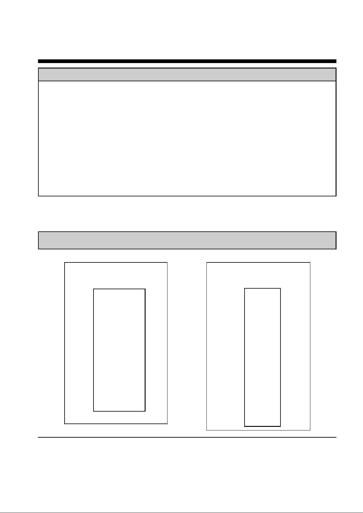
XE9624F
Pin Configuration
1 40
2 39
3 38
4 37
5 36
6 35
7 34
8 33
9 32
10 31
11 30
12 29
13 28
14 27
15 26
16 25
17 24
18 23
19 22
20 21
RESET
AR
RXD
/DTR
/AA
/CTS
OH
TXD
/RTS
/HS
/RI
TIP
RING
+5V
/DSR
/DCD
AMP
GND
XE9624FS
Pin Configuration
VCC
Reset
TXD
RXD
\AA
\RTS
\DTR
\RI
\HS
\DCD
\CTS
\DSR
OH
AR
AMP
Gnd
Tip
Ring
1
2
3
4
5
6
7
8
9
10
11
12
13
14
15
16
17
18
Pin Configurations
Page 5

XE9624F/XE9624FS XECOM\5
AT Commands
The XE9624F and XE9624FS use the Hayes "AT" commands for configuration and control.
Extensions to the AT commands support fax operation. The following section describes how
to use the AT command format and lists the AT commands, Registers and Result codes
used to control modem operation.
Modes of Operation
The "AT" commands have three operational modes; Command, Fax and Data Modes.
Data Mode: The XE9624F/FS enters data mode after it makes a connection with a
remote modem and issues an appropriate "CONNECT" result code. In the Data Mode
the modem sends all data on the Transmit Data line to the remote modem and puts
data from the remote modem onto the Received Data line for the host equipment.
When the modem exits data mode, it issues a "NO CARRIER" result code.
Command Mode: The XE9624F/FS enters command mode on power-up, reset, a lost
connection, or receipt of an escape code. When in command mode, the modem
accepts command line instructions from the host on transmit data. More than one
instruction may be placed on each command line. Appropriate result codes are
returned to the host on received data. The AT commands allow the host to configure
the modem for a specific application.
Fax Mode: The XE9624F/FS enters fax mode after it receives the AT+FCLASS=1
command. In fax mode commands and responses are issued at 19,200 bits per
second; the character format is 8 bits no parity. The modem accepts Class 1 fax
commands only while in the fax mode. The A/, ATO, AT&T and escape commands are
not valid in fax mode.
Command Line Format
Command lines issued to the modem follow a strict format. Each command begins with the
prefix AT. The command line is stored in the command buffer and executed upon receipt of
a carriage return. Untilexecuted, the command line can be editied with the backspace key.
Command Prefix - Each command, except for the A/ command, begins with the AT prefix.
The "A" and "T" may be either both caps or both lower case but cannot be of different cases.
The prefix identifies the speed and parity of the commands sent to the modem by the host.
Speed is determined by measuring the width of the incoming bits. Parity is determined by
comparing the parity bit of the "A" and the "T." Result codes are sent at the speed and
parity determined by the prefix.
Page 6

6/XECOM XE9624F/XE9624FS
Command Line - Commands may be joined in a single command line up to 40 characters
long. Commands are executed in the sequence they appear. Spaces may be inserted into
the command line to improve readability. Spaces do not fill space in the command buffer. A
carraige return terminates the command line and causes the commands to be executed.
Register S3 allows the user to select a character other than a carriage return to terminate the
command line.
Command Buffer - No more than 40 characters, including the AT prefix, may be loaded into
the command buffer. If the command buffer overflows, the modem issues an "ERROR"
result code and commands are not executed.
Command Line Editing - The backspace can be used to edit the command line before it is
executed. Hiting the backspace key, or Control and H simultaneously on some systems,
erases the previous character in the command line. All of the characters in the command
line can be erased escept for the "A" and "T." Register S5 allows the user to select another
character other than a backspace to edit the command line.
Re-Execute Last Command - The A/ command causes the modem to reexecute the last
command line. This is the only command which does not require the "AT" prefix.
Ommitted Parameters - Most commands include a parameter which determines how the
functions will be set. When the command parameter is omitted from the command string, it
is assumed to be a 0.
Escape Characters - A 3 character escape sequence maybe entered while in data mode to
switch the modem into command mode while on line. The escape character, set by Register
S2, must be entered 3 times in succession within a 1 second guard time to execute the
escape. The default escape sequence is "+++."
Result Codes - The modem issues a result code after each action. Result codes may be
provided as full words, numeric codes or may be disabled all together. Each result code
ends with a carriage return when numeric resul codes are chosen. When full word result
codes are chosen, a Line feed and Carriage Return preceed abd follow each result code.
Page 7

XE9624F/XE9624FS XECOM\7
AT Command List
A - Answer Command -
Bn - Select Communications Standard
n=0 Selects CCITT standards
n=1 Selects Bell standards
D - Dial Command -
P = Pulse dial
T = Tone dial
R = Connect as an answering modem
W = Wait for dial tone
, = Pause for the duration ofr S8
@ = Wait for silence
! = Switch hook flash
; = Return to the command state
En - Command Echo
n=0 Do not echo commands
n=1 Enable command echo*
Hn - Switch Hook Control -
n=0 Switch hook relay closes
n=1 The switch hook relay opens
In - Modem Identification
Ln - Speaker Volumel -
n=0 Low speaker volume
n=1 Low speaker volume
n=2 Moderate speaker volume*
n=3 High speaker volume
Mn - Speaker Activity -
n=0 Speaker off
n=1 Speaker on until carrier received*
n=2 Speaker remains on
n=3 Speaker on after dialing until carrier
is detected.
On - On Line
n=0 Return On Line with no retrain
n=1 Initiate retrain while returning On
line.
Qn - Responses
n=0 Send responses*
n=1 No Responses
n=2 Send responses only in Originate
Sr? - Interogate Register Sr=n - Set Register Value -
Vn - Result Codes -
n=0 Numeric Result Codes
n=1 English Word Result Codes*
Xn - Result Code Set Z - Reset -
&Cn - DCD Operation
n=0 DCD is forced active.*
n=1 DCD indicates a valid carrier signal
&Dn - DTR
n=0 DTR is ignored by the modem.*
n=2 Modem disconnects if the host
rescinds DTR.
n=3 The modem performs a soft reset
when DTR is rescinded.
&Fn - Defaults
n=0 Modem configuration to the default
settings stored with AT&W0.*
n=1 Modem configuration to the default
settings stored with AT&W1.
Page 8

8/XECOM XE9624F/XE9624FS
AT Command List (continued)
&Ln - Line Type
n=0 Modem operates on dial-up lines.*
n=1 Modem operates on leased lines
&Qn - Communications Format
n=0 Sets the modem for normal,
unbuffered operation.
&Sn - DSR Operation
n=0 DSR always active.*
n=1 DSR in accordance with V.25.
&Tn - Test Modes
n=0 Exit test mode
n=1 Local analog loopback
n=3 Initiate local digital loopback
n=4 Respond to remote loop request*
n=5 Deny remote loop request
n=6 Intiate a Remote Digital loopback
n=7 Remote digital loopback w self-test
n=8 Local analog loopback w self-test
&V - View Active Profile &Wn - Store Profile -
n=0 Stores the current configuration in
memory location 0.*
n=1 Stores the current configuration in
memory location 1.
&Yn - Recall Profile
n=0 Use memory location 0.*
n=1 Use memory location 1.
Result Code Summary
DIGIT CODE WORD CODE MEANING
0 OK Successfully executed command line
1 CONNECT 300 bps connection established
2 RING Ring signal detected
3 NO CARRIER Carrier not detected within Register S7 detect time
4 ERROR Error found in command line; returns to command line
5 CONNECT 1200 1200 bps connection established
6 NO DIAL TONE No dial tone detected within 5 Sec. after going off-hook
7 BUSY Busy signal detected after automatically dialing a call
8 NO ANSWER Five seconds of silence was not detected when using the @
command in the Dial command line
10 CONNECT 2400 Connection established at 2400 bps
13 DATA Connected in data mode after automatically answering the call.
15 FAX Connected in fax mode after automatically answering the call.
+F4 +FCERROR Fax carrier errror detected.
* Command Default values
Page 9

XE9624F/XE9624FS XECOM\9
Class 1 Fax Command List
+FCLASS? - Service Class Indication
0 = Configured as a data modem
1 = Configured for Service Class 1.
2 = Reserved for Srvice Class 2.
3 = Reserved for Service Class 3.
+FCLASS=? - Service Class Capability
0 = Configured as a data modem
1 = Configured for Service Class 1.
2 = Reserved for Srvice Class 2.
3 = Reserved for Service Class 3.
+FCLASS=n - Set Service Class
0 = Configured as a data modem
1 = Configured for Service Class 1.
2 = Reserved for Service Class 2.
3 = Reserved for Service Class 3.
+FTS<time> - Transmit Silence
+FRS<time> - Receive Silence
+FTM<mod> - Transmit Fax
3 V.21 Channel 2, 300 bps
24 V.27ter, 2400 bps
48 V.27ter, 4800 bps
72 V.29, 7200 bps
96 V.29, 9600 bps
+FRM<mod> - Receive Fax
3 V.21 Channel 2, 300 bps
24 V.27ter, 2400 bps
48 V.27ter, 4800 bps
+FTH<mod> - Transmit HDLC Data
3 V.21 Channel 2, 300 bps
24 V.27ter, 2400 bps
48 V.27ter, 4800 bps
72 V.29, 7200 bps
96 V.29, 9600 bps
+FRH<mod> - Receive HDLC Data
3 V.21 Channel 2, 300 bps
24 V.27ter, 2400 bps
48 V.27ter, 4800 bps
+FAA=n - Data/Fax Auto Answer
0 = Answer as a fax modem only
1 = Either a fax or data modem
+FF - Enhanced Flow Control
+FRTn - Receive Test Data
+FTTn=m - Transmit Test Data
Page 10

S0 0-255/rings Number of rings to answer on 000
S1 0-255/rings Count number of incoming rings 000
S2 0-127/ASCII Escape character 043
S3 0-127/ASCII Carriage return character 013
S4 0-127/ASCII Line feed character 010
S5 0-32,127/ASCII Backspace character 008
S6 2-255/sec Dial tone wait time 002
S7 1-60/sec Wait time for remote carrier 030
S8 0-255/sec Comma pause time 002
S9 1-255/0.1 sec Carrier detect response time 006
S10 1-255/0.1 sec Delay from loss of carrier to hang up 014
S11 50-255/msec DTMF dialing speed 095
S12 0-255/0.02 sec Escape guard time 050
S13 — Reserved
S14 Bit Mapped E,Q,V,T,P,D,A,R accept/ignore 171
S15 — Reserved
S16 Bit Mapped Modem loopback tests 000
S17 — Reserved
S18 0-255/sec Modem test timer 000
S19 — Reserved
S20 — Reserved
S21 Bit Mapped J, &R, &D, &C, &S, Y 000
S22 Bit Mapped L, M, X, &P, &T4, &T5, 118
DTE speed and parity
S23 Bit Mapped &T4,&T5, DTE speed, parity 103
S24 — Reserved
S27 Bit Mapped &Q, &L, &X, B commands 073
S28 Bit mapped &Pn 000
REG. RANGE/UNITS DESCRIPTION DEFAULT
10/XECOM XE9624F/XE9624FS
S-Register Summary
Page 11

XE9624F/XE9624FS XECOM\11
Modem Applications Schematic
Power Supply Characteristics(TA = 0 - 70°C, Vcc = 5v ±5%)
Symbol Parameter Min Typ Max Units Comments
Vcc Supply Voltage 4.75 5.0 5.25 V
Icc Vcc Supply Current 40 mA All outputs Disconnected
Iccpd Sleep Mode Current 10 mA
Power Management:
The XE9624F and XE9624FS have an integrated power management
capability. If RXD, DTR, and RI lines remain inactive for 5 seconds, the modem automatically enters
sleep mode. In the sleep mode power consumption drops to less than 50 milliwatts.
Page 12

PARAMETER MIN TYP MAX UNIT COMMENTS
DTMF Level -2.2 0 dBm
DTMF Twist (Balance) 3 dB
Pulse Dialing Make/Break 39/61 % USA
33/67 % CCITT
Pulse Interdigit Interval 785 ms
Billing Delay Interval 2.0 sec.
Tone Detection Bandpass Frequency 290 665 Hz 3 dB point
Tone Detection OFF to ON Threshold -33 dBm into 600 ohms
Tone Detection ON to OFF Threshold -35 dBm into 600 ohms
Dial Tone Detect Duration 3.0 sec.
Ringback Tone Detect Duration 0.75 sec.
Cadence 1.5 sec. OFF/ON Ratio
Busy Tone Detect Duration 0.2 sec.
Cadence 0.67 1.5 sec. OFF/ON Ratio
ABSOLUTE MAXIMUM RATINGS*
Electrical Specifications
SUPPLY VOLTAGE - Vcc +6.5 Volts
DC INPUT VOLTAGE -0.6 Volts to +6.5 Volts
STORAGE TEMPERATURE RANGE -25° C TO +100° C
LEAD TEMPERATURE (Soldering, 2 sec per wave) 260° C
OPERATING TEMPERATURE RANGE 0 TO 70° C
*Exceeding these values may result in permanent damage to the device.
DIGITAL INPUTS Input High Input Low
/DTR, TXD, RESET min. 2.0 V max. 0.8 V
DIGITAL OUTPUTS Output High Output Low Current Drive
AR, /RI min. 2.4 V max. 0.8 V 15 ma
/CTS, /DSR, /DCD, RXD min. 2.4 V max. 0.4 V 1.6 ma
I/O Characteristics
Signals Description
12/XECOM XE9624F/XE9624FS
Page 13

Telephone Line Impedance Match 600 ohms
Ring Detect Sensitivity 38 Vrms
(on hook, Type B ringer)
Telephone Line Holding Current 20 100 mA
Telephone Line Interface Specifications
PARAMETER MIN TYP MAX UNIT
XE9624F/XE9624FS XECOM/13
Sample Fax Reception
Host Fax Modem Comments
AT+FCLASS=1 Set for Fax
"OK" waits for ring
"Ring"
ATA Answers CAll
"CONNECT"
Sends Flags
"CONNECT"
NSF Data Frame and send
"CONNECT"
CSI Data Frameand send
"CONNECT"
DIS Data Frame and send
"OK", drop carrier
AT+FRH=3 Buffers Frames Remote
"CONNECT" sends TSI
Pass TSI
"OK"
AT+FRH=3 Buffers Frames Remote fax
"CONNECT" sends DCS
AT+FRM=96 Set to 9600 bps
"CONNECT" Remote fax
Pass TCF sends TCF
"NO CARRIER"
Host Fax Modem Comments
Pass DCS
"OK"
AT+FTH=3 Sends flags
"CONNECT"
CFR data Frame and Send
"OK", drop carrier
AT+FRM=96 Set to 9600 bps Remote fax
Pass Page Data sends page
"NO CARRIER"
AT+FRH=3 Buffers Frames Remote fax
"CONNECT" sends EOP
Pass EOP data
"OK"
AT+FTH=3 Sends flags
"CONNECT"
MCF data Frame and Send
"OK", drop carrier
AT+FRH=3 Buffers Frames Remote fax
"CONNECT" sends DCS
Pass DCS Frame Remote fax
"OK" Disconnects
ATH0 hangs up
"OK"
Page 14

14/XECOM XE9624F/XE9624FS
Sample Fax Transmission
Host Fax Modem Comments
AT+FCLASS=1 Set for Fax
Operation
"OK"
ATDT5846161 Modem Dials Remote Fax
CONNECT Answers and
sends Flags
Buffers Frames NSF, CSI, &
Pass NSF DIS sent by
"OK" remote
AT+FRH3 Buffers Frames
Pass CSI
"OK"
AT+FRH3 Buffers Frames
Pass DIS
"OK"
AT+FTH3 Sends flags
"CONNECT"
TSI data Frame and send
"CONNECT"
DCS Data Frame and send
"OK", drop carrier Tx squelch
after DCS
AT+FTS8 Wait 80 msec
"OK"
AT+FRM96 Set Tx to 9600bps
"CONNECT"
Send TCF Transmit TCF
(training) "OK"
Host Fax Modem Comments
AT+FRH3 Buffers Frames Remote
"CONNECT" sends CFR
Pass CFR
"OK", drop carrier Tx squelch
"NO CARRIER" after DCS
AT+FTM96 Set to 9600bps
"CONNECT"
Page Data Sends Page Data
"OK"
AT+FTH3 Sends flags
"CONNECT"
EOP Frame and send
"OK", Drop Carrier Tx squelch
after DCS
AT+FRH3 Buffers frames
"CONNECT" Remote
Pass MCF data sends MCF
"OK"
"NO CARRIER"
AT+FTH3 Sends Flags
"CONNECT"
DCN Frane & Send
"OK", Drop Carrier Tx Squelch
after DCS
ATH0 Hangs up Remote
"OK" Disconnect
Page 15

XE9624F/XE9624FS XECOM\15
FCC Instructions
FCC Registration Number: DWEUSA-20716-MM-E
Ringer Equivalence: 0.8B
This product complies with Part 68 of the FCC Rules and Regulations. Each device shipped includes a label which contains the FCC
Registration Number and Ringer Equivalence (REN). If requested, this FCC information must be provided to the telephone
company. A registration label must be affixed to the cabinet's exterior for each device mounted within a closed assembly.
Ringer Equvalence (REN) is used to calculate the number of devices you may connect to one telephone line and still have all of the
devices respond to an incoming call. Typically, the sum of the RENs of all devices connected to one line should not exceed five
(5.0). Contact your local telephone company to determine the maximum REN for your area.
Mount this device in the final assembly so as to prevent exposure to any hazardous voltages in the system and to preserve the high
voltage protection between Tip/Ring and the rest of the system. Installation must provide adequate separation and restraint of cables
and cords. Xecom recommends maintaining a minimum of .100 inches between the Tip and Ring traces and all other circuits. No
circuitry may be added between Tip/Ring and the telephone line connection unless specifically allowed by the rules.
This device requires use of an RSOC RJ-11C jack for the telephone line connection. The jack selected must be certified to meet
FCC Part 68 subpart F requirements.
If you experience trouble with this device, contact XECOM at (408)945-6640 to obtain service. There are no repairs the customer
may make to this device. If your system causes harm to the telephone network, the telephone company may discontinue service
temporarily until the problem has been corrected or it is demonstrated that the device is not malfunctioning. If possible, you will be
notified in advance that service is being discontinued. If advance notice is not practical, you will be notified as soon as possible.
Your telephone company may make changes to their facilities, equipment, or operation that affect proper functioning of your
equipment. You will be notified in advance of such changes to give you the opportunity to maintain uninterrupted telephone service.
This device cannot be used on coin operated telephone lines provided by the telephone company. Connection of this equipment to
party lines is subject to state tariffs.
Any one using this device for fax transfer must include sender identification information as required in the Telephone Consumer
Protection Act of 1991. The Telephone Consumer Protection Act of 1991 makes it unlawful to send a fax without clearly identifying
the fax sender (business or individual) and the number of the transmitting fax machine. This information may be provided either on
the first page of the fax or in the top or bottom margin of each page. The number listed may not be a 900 number or other number
for which charges exceed local or long distance transmission.
The final assembler must provide these FCC instructions to the end user of the equipment.
Page 16

Terms of Sale
Devices sold by XECOM are covered by the warranty provisions appearing in its Terms of Sale only.
XECOM makes no warranty, express, statutory, implied, or by description regarding the information set
forth herein, or regarding the freedom of the described devices from patent infringement. XECOM
makes no warranty of merchantability or fitness for any purposes. XECOM reserves the right to
discontinue production and change specifications and prices at any time and without notice. This
product is intended for use in normal commercial applications. Applications requiring extended
temperature range, unusual environmental requirements, or high reliability applications, such as
military, medical life-support or life-sustaining equipment, are specifically not recommended without
additional processing and authorization by XECOM for such application.
Xecom assumes no responsibility for the use of any circuitry other than circuitry embodied in a Xecom
product. No other circuits, patents, or licenses are implied.
Life Support Policy
Xecom's products are not authorized for use as Critical Components in Life Support Devices or
Systems.
Life Support Devices or Systems are devices or systems which, (a) are intended for surgical implant
into the body, or (b) support or sustain life, and whose failure to perform, when properly used in
accordance with instructions provided in the labeling, can be reasonably expected to result in
significant injury to the user.
A Critical Component is any component of a life support device or system whose failure to perform
can be reasonably expected to cause failure of the life support device or system, or to affect its safety
or effectiveness.
Copyright, Xecom © 1994
While Xecom, Inc. has made every effort to ensure that the information presented here is accurate, Xecom will not be liable for any
damages arising from errors or omission of fact. Xecom reserves the right to modify specifications and/or prices without notice.
Product mentioned herein are used for identification purposes only and may be trademarks and/or registered trademarks of their
respective companies.
xecom
X e com Incorporated
374 Turquoise Str eet , Mi lpitas, CA 95035
Ph:408-945-66 40 Fax:4 08-94 2 - 1 346
 Loading...