

XECOM XE0046
High-Performance Quad DAA Module
XE0046
02/98
Description
Xecom created the XE0046 for high-performance,
multi-line applications. The XE0046 integrates
four high performance DAA's into a single
compact module. Each DAA circuit operates
independently of all the others.
Like all of Xecom's DAA modules, the XE00046
integrates a Ring Detect Circuit, Loop Current
Holding Circuit, Solid-State Hookswitch, and
Telephone Line Transformer for each line. The
XE0046 also provides each line with a path for
the Caller ID signal from the telephone network
and a two-to-four wire convertor. The two-to-four
wire convertor separates the receive signal from
the transmit signal.
Below is a list of the special features incorporated
into the XE0046 for high-performance, multi-line
applications.
XE0046 Features
* Four Individual DAA's in a Single Package;
* Each DAA supports 33,600 bps data transfer;
* Each DAA provides a path for the Caller ID
signal from t
he phone company central office;
* Each DAA includes a 2/4 four wire convertor;
* Each DAA passes network signaling up to 0
dBm without distortion.
* Small Size: 2.5 inches long, 1.5 inches wide,
and 0.6 inches high;
* FCC Part 68 Compliant;
* Individual Ring Detection for each line;
* Each DAA integrates a Low-Distortion
Telephone Line Transformer;
* Each DAA provides a1500 volts isolation
between the phone line and all other circuits;
* Solid-State Hookswitch Control for each line;
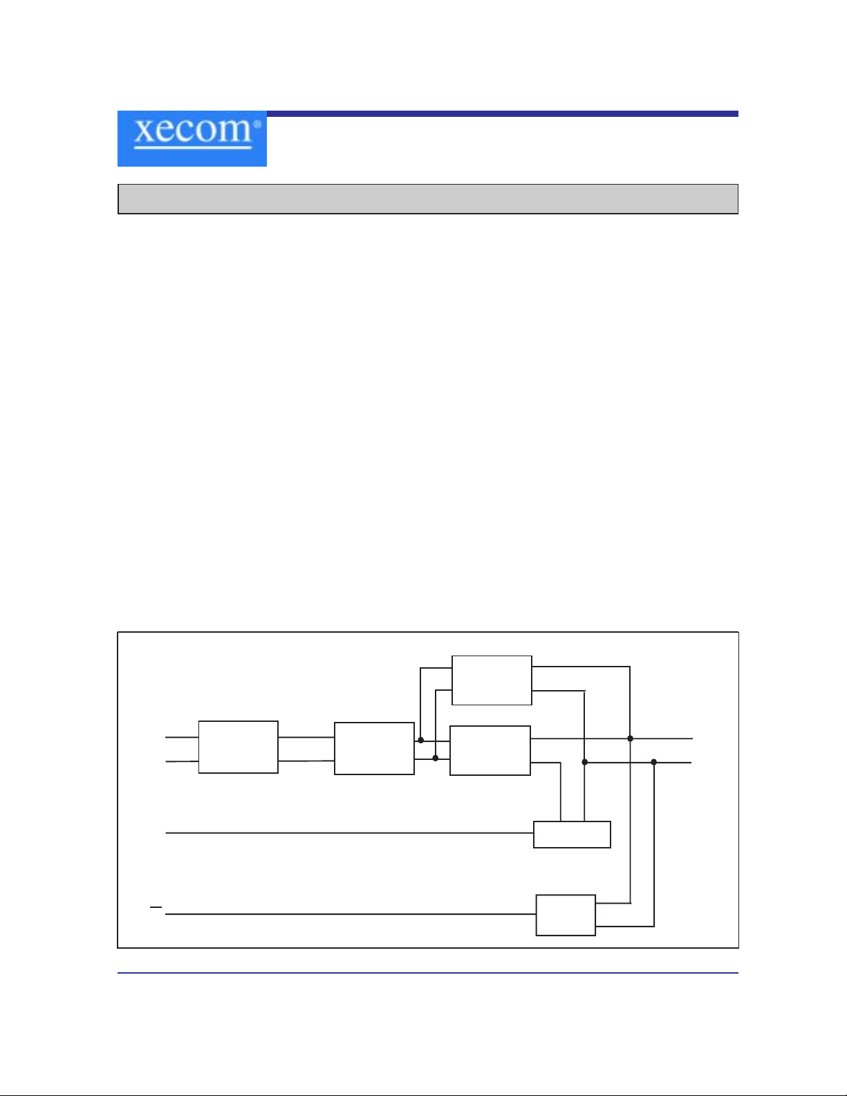
XE0046 Block Diagram (This Block Diagram represents each DAA within the XE0046)
Line
Transformer
Line Current
Holding
Circuit
Hookswitch
Ring
Detector
OH
RI
Tip
Ring
2/4 Wire
Convertor
TX
RX
Caller ID
XECOM (2) XE0046
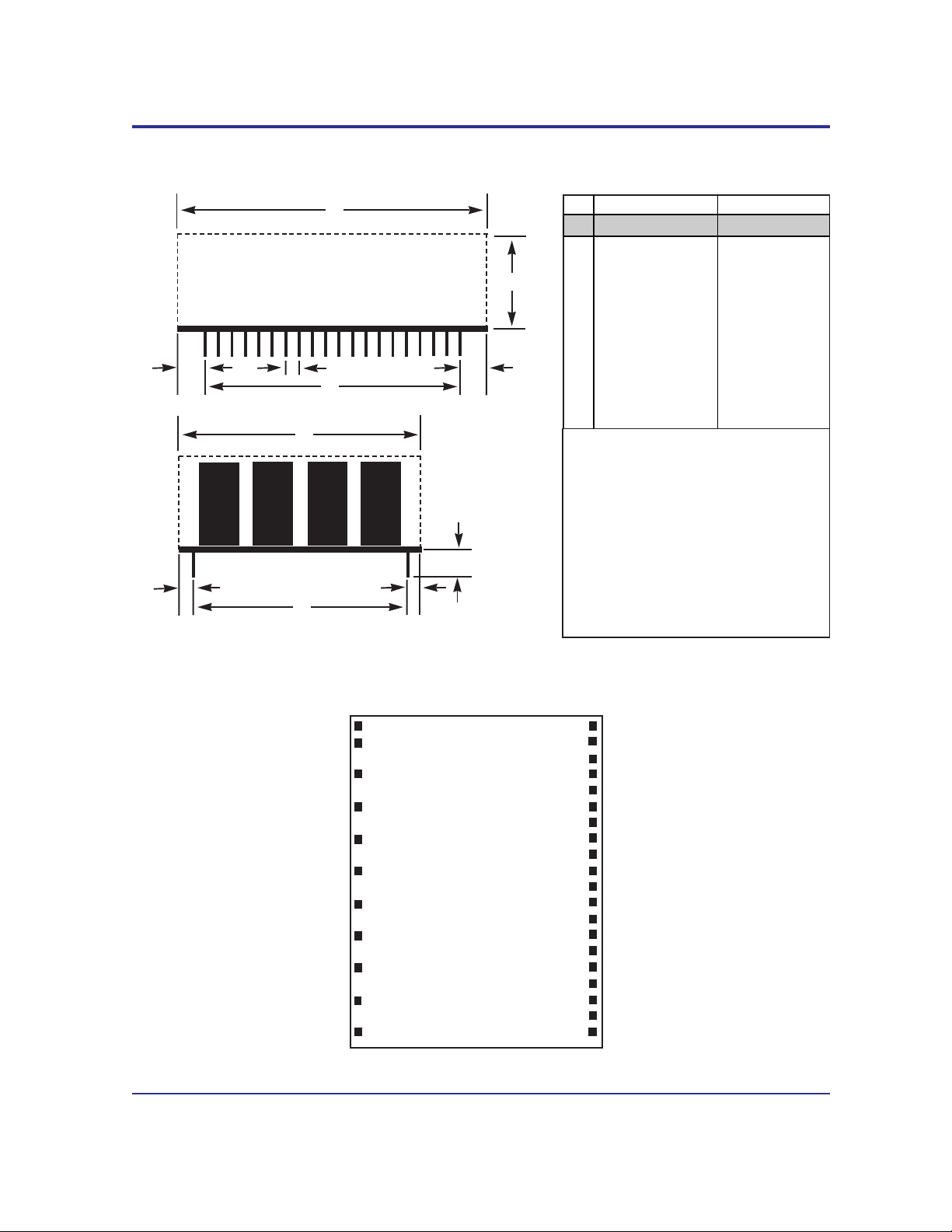
XE0046 Mechanical Specifications
A
B
C
D
E
F
F
H
G
H
J
A 2.480 2.520 62.99 64.01
B 0.580 0.620 14.73 15.75
C 1.480 1.520 37.59 38.61
D 0.090 0.110 2.29 2.79
E 1.890 1.910 48.01 48.51
F 0.280 0.320 7.11 8.13
G 1.390 1.410 35.31 35.81
H 0.040 0.060 1.02 1.52
J 0.125 - 3.18 -
Inches Millimeters
Dim Min Max Min Max
Notes:
These dimensions reflect the module's
maximum envelope.
I/O pins are .025 inch square, tin-plated.
Warning:
There are un-insulated electrical conductors on the underside of the XE0046.
No exposed electrical conductors should
be routed under the module
XE0046 Pin Configuration
Vcc
Vdd
Tip1
Ring1
Tip2
Ring2
Tip3
Ring3
Tip4
Ring4
Gnd
1
2
4
6
8
10
12
14
16
18
20
TX1
RX1
OH1
/RI1
N/C
TX2
RX2
OH2
/RI2
N/C
TX3
RX3
OH3
/RI3
N/C
TX4
RX4
OH4
/RI4
N/C
40
39
38
37
36
35
34
33
32
31
30
29
28
27
26
25
24
23
22
21

XECOM (3) XE0046
XE0046 Signal Descriptions
1 VCC VCC provides the + 5 volt power source for the XE0046.
2 Vdd Vdd provides the -5 volt power source to the XE0046
4, 8, 10, 16 Tip(n) Tip provides the second connection to the telephone network (RJ11 Pin 3)
on each of the four internal DAAs. Tip has 1500 volts isolation from the rest
of the circuitry. This isolation must be preserved throughout the system.
6, 10, 14, 18 Ring(n) Ring is one of two signals which form the telephone network connection
(RJ11 Pin 4) on each of the four internal DAAs. The XE1046 is not sensitive
to the polarity of the battery voltage on the telephone line. Ring has 1500
volts isolation from the rest of the circuitry which must be preserved
throughout the system.
20 GND This signal is used as common reference for all of the control signals in the
XE0046. Signals on Tip and Ring are not referenced to ground.
21, 26, 31, 36 N/C No Connect
22, 27, 32, 37 /RI(n) Ring Indicate, output, active low, TTL, RI provides a half-wave
representation of the Ring appearing on each telephone line.
23, 28, 33, 38 OH(n) Hook-switch relay control an active high input. A high on OH closes the
internal relay within each DAA and connects the equipment to that telephone
line.
24, 29, 34, 39 RX(n) RX is the analog output from each DAA. RX is referenced to ground. The
level of RX will be within 1 dB of the received signal on the telephone line.
25, 30, 35, 40 TX(n) TX is the analog input to each DAA. The signal level at TX will be within 1
dB of the level of the transmitted signal on Tip and Ring. TX is referenced
to ground.
Pin Name Description
Note: The "n" designates the DAA with which the signal connects. Only power and ground signals are
common to all DAA's.

XECOM (4) XE0046
Electrical Specification
(Vcc = +5 Volts ±10%, Vdd = -5 Volts ±10%,Ta=0 to 70 deg C)
Icc Off Hook, Vcc = 5.0 Volts 10 15 mA
Idd Vdd = -5.0 volts 3 5 mA
Transmit Insertion loss 600 Ohm Impedance, 1000 Hz -1.0 0 1.0 dB
Receive Insertion loss 600 Ohm Impedance, 1000 Hz -1.0 0 1.0 dB
Line Impedance At 1000 Hz, 540 600 660 Ohms
Ring Detect Min. AC voltage between Tip & 38 150 Vrms
Sensitivity (on-hook) Ring Type B ringer
Ring Detect Ringing voltage of 40 Vrms 100 uA
Peak Current applied between Tip & Ring
Ring Detect No Ringing Voltage present 10 uA
Idle Current
Ring Indicate Output Ring Voltage present on Tip 0.2 0.5 Volts
Voltage & Ring
Loop Current Switch ON: (off-hook) 2.0 3.0 Volts
Control Voltage OFF: (on-hook) 0.2 0.5 Volts
Loop Current Switch 15 25 mA
Control Current
Loop Current Off-Hook current draw from 0 100 mA
Telephone Line
Total Harmonic 1800 Hz, -9 dBm signal level -85 dBm
Distortion
Caller ID Insertion Loss Hookswitch open -8.0 -6.0 -4.0 dBm
Parameter Conditions Min Typ Max Units

XECOM (5) XE0046
Telephone Line Connection Information
When developing a product to be connected to the telephone line, it is necessary to use a circuit described as a
Data Access Arrangement (DAA) which is approved by the appropriate governmental agency. In the US, for
example, this agency is the Federal Communications Commission (FCC), while in Canada it is Industry Canada.
These agencies test and approve the product to ensure that it meets their specifications, thereby protecting the
telephone system from damage and protecting the user from high voltage transients (such as lightning strikes) which
may come down the telephone line.
The XE0046 has been designed to meet FCC Part 68 requirements for hazardous voltage, surge protection and
leakage current. If the system transmits data, or DTMF tones on the telephone line, the user must certify that these
transmitted signals meet FCC requirements for maximum transmission levels of out of band energy and billing delay.
Full details may be obtained from the FCC under Part 68 of the FCC Rules and Regulations, or in Title 47 of the
Code of Federal Regulations, however the basic requirements are as follows:
1. Maximum Transmit Level
For the normal “permissive” (standard) telephone line, equipment which transmits data (such as a modem) must not
exceed a transmission level of -9 dBm.
2. Out of Band Energy
Data equipment must not transmit “out of band” energy on the telephone line which exceeds the following limits:
Frequency Range Max. Power
200Hz to 3990Hz -9 dBm
3990Hz to 4005Hz -27 dBm
4005Hz to 16kHz -16 dBm
8kHz to 94kHz -47 dBm
86kHz to 270kHz -46 dBm
270kHz to 6MHz -6 dBm
3. DTMF Transmission Level
If the system is capable of DTMF dialing, the maximum DTMF transmission level must be less than 0 dBm averaged
over a 3 second interval.
4. Billing Delay
A delay of 2 seconds or greater is required after the time the XE0046 is taken “off hook” and before any information
is transmitted. This is required to ensure that billing information may be exchanged between telephone company
central offices without interference.
The user of the XE0046 must certify to the FCC that the final system meets the requirements of Part 68 which
include the criteria above as well as the high voltage isolation provided by the XE0046. This is generally
accomplished through an independent testing lab which test the System and submits the proper paperwork to the
FCC for approval. Since the XE0046 already complies with FCC Part 68 rules, this is a relatively simple proces
s.

XECOM XE0046
Copyright, Xecom © 1998
While Xecom, Inc. has made every effort to ensure that the information presented here is accurate, Xecom will not
be liable for any damages arising from errors or omission of fact. Xecom reserves the right to modify specifications
and/or prices without notice. Product mentioned herein are used for identification purposes only and may be
trademarks and/or registered trademarks of their respective companies.
Terms of Sale
Devices sold by XECOM are covered by the warranty provisions appearing in its Terms of Sale only. XECOM
makes no warranty, express, statutory, implied, or by description regarding the information set forth herein, or
regarding the freedom of the described devices from patent infringement. XECOM makes no warranty of
merchantability or fitness for any purposes. XECOM reserves the right to discontinue production and change
specifications and prices at any time and without notice. This product is intended for use in normal commercial
applications. Applications requiring extended temperature range, unusual environmental requirements, or high
reliability applications, such as military, medical life-support or life-sustaining equipment, are specifically not
recommended without additional processing and authorization by XECOM for such application.
Xecom assumes no responsibility for the use of any circuitry other than circuitry embodied in a Xecom product. No
other circuits, patents, or licenses are implied.
Life Support Policy
Xecom's products are not authorized for use as Critical Components in Life Support Devices or Systems.
Life Support Devices or Systems are devices or systems which, (a) are intended for surgical implant into the body,
or (b) support or sustain life, and whose failure to perform, when properly used in accordance with instructions
provided in the labeling, can be reasonably expected to result in significant injury to the user.
A Critical Component is any component of a life support device or system whose failure to perform can be
reasonably expected to cause failure of the life support device or system, or to affect its safety or effectiveness.
Xecom Incorporated
374 Turquoise Street,Milpitas, CA 95035
Ph:408-945-6640 Fax:408-942-1346 E-Mail info@xecom.com
 Loading...