

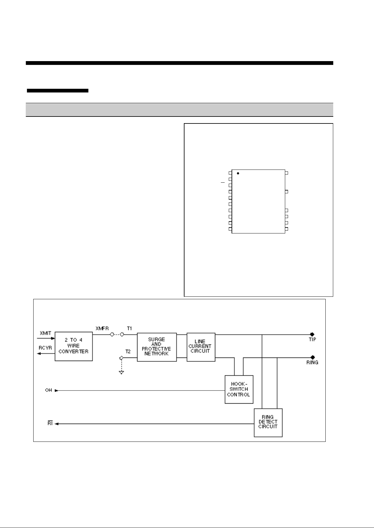
DAA with 2/4 Wire Hybrid
XE0002B
Features
• Small Size - 1.25" x 1.0" x 0.5"
• FCC Part 68 Compliant
• Ring Detection
• 2 to 4 Wire Converter
• 1500 Volt Isolation
• 800 Volt Surge Protection
• Hookswitch Control
Description
The XE0002B Data Access Arrangement provides a
'direct connect' telephone line interface. It complies
with FCC Part 68 hazardous voltage, surge and leakage
current specifications. This component may be used as
the direct connect telephone line interface for virtually
any application in which voice or data is to be
transmitted over the public switched telephone network.
The XE0002B provides high voltage isolation,
independent on/off hook control, ring detection circuitry
and a 2 to 4 wire converter hybrid for use in modem
applications. It operated from ±5 volt power supplies
and occupies 1.25 square inches of board space.
1 • 20
2
3
4 17
5
6
7 14
8 13
9 12
10 11
VDD
Vcc
RI
RCVR
XMIT
XMFR
T1
OH
GND
T2
TIP
RING
N/C
N/C
N/C
N/C
PIN CONFIGURATION
C A U T I O N
PINS 17 & 20 HAVE 1500V ISOLATION FROM THE REST OF
THE CIRCUITRY. THIS ISOLATION SHOULD BE
PRESERVED THROUGHOUT THE SYSTEM
XECOM
(Top View)
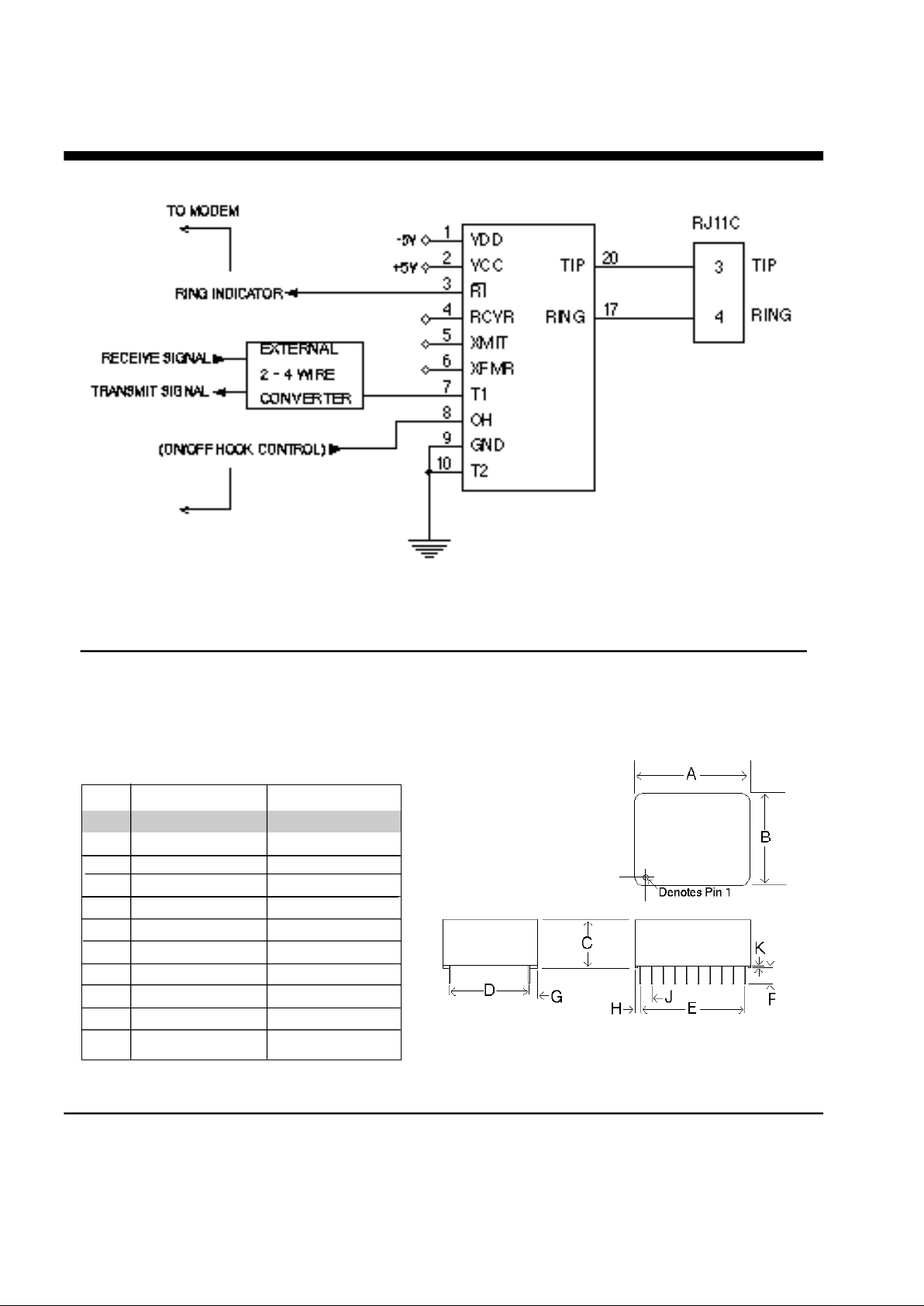
Block Diagram
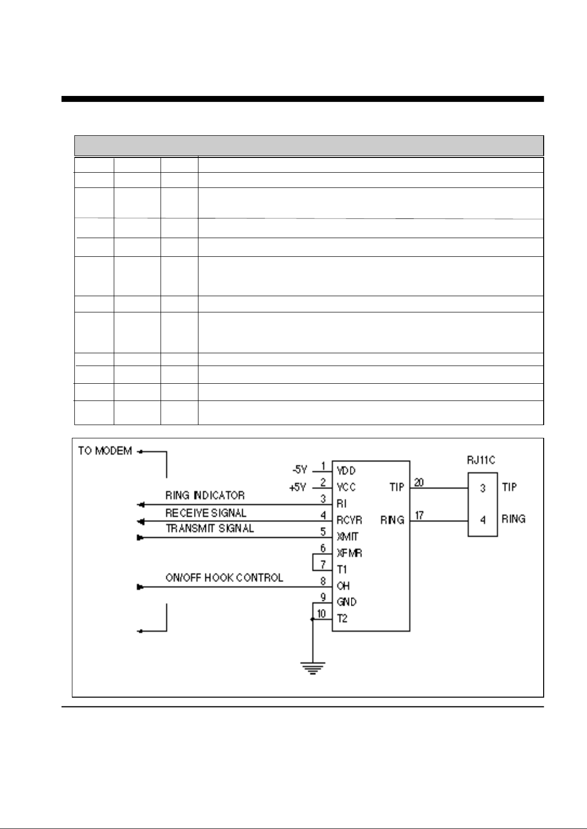
Typical Connection Diagram
2/XECOM XE0002B
PIN NAME I/O DESCRIPTION
Pin Descriptions
1 VDD --- -5 Volts.
2 VCC --- +5 Volts
3 \RI O Ring Indicator, output, active LO, TTL. When low indicates the
modem is receiving a ring signal.
4 RCVR O Analog signal output from the 2-4 wire convertor.
5 XMIT I Analog signal input to the 2-4 wire convertor.
6 XMFR I Analog input/output from the Surge and Protective Network to the
internal 2-4 wire convertor. Must be tied to pin 7, T1, to use the
internal 2-4 wire convertor.
7 T1 I Analog Signal input/output to the Surge and Protective network.
8 OH I Off-Hook controls the hookswitch relay within the XE0002B. A high
on OH closes the internal relay and connects the equipment to the
telephone line.
9 GND --- Ground.
10 T2 I Analog Signal input/output to the Surge and Protective network.
17 RING --- Ring connection to the phone line (RJ11 pin4) from the internal DAA.
20 TIP --- Tip connection to the phone line (RJ11 pin3) from the internal DAA.
Mechanical Specifications
Connection Diagram With External 2-4 Wire Converter
XE0002B XECOM\3
INCHES METRIC(MM)
PIN MIN MAX MIN MAX
A 1.235 1.265 31.37 32.13
B 0.985 1.015 25.02 25.78
C 0.490 0.510 12.45 12.95
D 0.890 0.910 22.61 23.11
E 0.890 0.910 22.61 23.11
F 0.125 --- 3.18 --G 0.040 0.060 1.02 1.52
H 0.165 0.185 4.19 4.70
J 0.090 0.110 2.29 2.79
K 0.020 0.025 0.51 0.64

4/XECOM XE0002B
1200bps Modem Using Sierra Semiconductor SC11007/SC11014
Typical Connection Diagram with Silicon Systems K-Series Family

XE0002B XECOM\5
INTERFACE TO EXAR XR2401/XR2402

Power Supply Current Vcc 6 10 mA
VDD 4 6 mA
Transmission Gain Gain between transmit input and -0.5 0 +0.5 dB
telephone line at 1800 Hz with
600 ohm termination
Telephone Line at 1800 Hz 540 600 660 Ohms
Impedance
Coupler Match Output impedance of external 531 536 541 Ohms
Input Impedance circuitry when T1 driven directly
to provide 600 ohm phone line
impedance match
Transhybrid Loss Attenuation between the trans- 10 18 dB
mitter input and receiver output
at 1kHz with 600 ohm termination
Attenuation Receive and Transmit attenuation 0.8 3 dB
at 300 Hz with 600 ohm termination
Transmit Input at 1800 Hz 8 10 12 KOhm
Impedance
Receive Output at 1800 Hz 10 100 Ohm
Ring Detect Min. AC voltage between Tip & 38 Vrms
Sensitivity (on hook) Ring Type B ringer
Loop Current Switch ON: (off hook) 2.0 3.0 Volts
Control Voltage OFF: (on hook) 0.5 0.8 Volts
Loop Current Switch 1.0 2.0 mA
Control Current
D.C. Electrical Specification
(Vcc=+5v ±10%, Vdd=-5v ±10%, Ta=0 to 70 deg C)
Parameter Conditions Min Typ Max Units
FCC User Instructions
RINGER EQUIVALENCE 0.9B
6/XECOM XE0002B

XE0002B XECOM\7
Typical Characteristics

Telephone Line Connection Information
When developing a product that is to be connected to the telephone line, it is necessary to use a circuit described as a Data
Access Arrangement (DAA) which is approved by the appropriate governmental agency. In the US, for example, this agency is
the Federal Communications Commission (FCC), while in Canada it is the Department of Communications (DOC). These
agencies test and approve the product to ensure that it meets their specifications, thereby protecting the telephone system from
damage and protecting the user from high voltage transients (such as lightning strikes) which may come down the telephone
l i n e .
The XE0002B has been designed to meet all FCC Part 68 requirements for hazardous voltage, surge protection and leakage
current. If the system developed transmits data, or DTMF tones on the telephone line, the user must certify that the signals
transmitted from the XE0002B meet basic FCC requirements for maximum transmission levels of out of band energy and billing
delay. Full details may be obtained from the FCC under Part 68 of the FCC Rules and Regulations, or in Title 47 of the Code of
Federal Regulations, however the basic requirements are as follows:
1. Maximum Transmit Level
For the normal “permissive” (standard) telephone line, equipment which transmits data (such as a modem) must not exceed a
transmission level of -9 dBm.
2. Out of Band Energy
Data equipment must not transmit “out of band” energy on the telephone line which exceeds the following limits:
F r e q u e n c y R a n g e Max. Power
2 0 0 H z t o 3 9 9 0 H z -9 dBm
3 9 9 0 H z t o 4 0 0 5 H z -27 dBm
4 0 0 5 H z t o 1 6 k H z -16 dBm
8 k H z t o 9 4 k H z -47 dBm
8 6 k H z t o 2 7 0 k H z -46 dBm
2 7 0 k H z t o 6 M H z -6 dBm
For modem applications, the out of band energy limit is normally ensured by the transmit filter in the modem circuitry.
3 . DTMF Transmission Level
If the system is capable of DTMF dialing, the maximum DTMF transmission level must be less than 0 dBm averaged over a 3
second interval.
4. Billing Delay
A delay of 2 seconds or greater is required after the time the XE0002B is taken “off hook” and before any data is transmitted.
This is required to ensure that billing information may be exchanged between telephone company central offices without
i n t e r f e r e n c e .
The user of the XE0002B must certify to the FCC that the final system meets the requirements of Part 68 which include the
criteria above as well as the high voltage protection that is provided by the XE0002B. This is generally accomplished through an
independent testing lab which will test the System and submits the proper paperwork to the FCC for approval. Since the
XE0002B already complies with FCC Part 68 rules, this is a relatively simple process.
JACK RJ11C RINGER EQUIVALENCE = 0.9B
REGISTRATION NUMBER DWE6TM - 72963 - WP - E
Copyright, Xecom © 1991
While Xecom, Inc. has made every effort to ensure that the information presented here is accurate, Xecom will not be liable for
any damages arising from errors or omission of fact. Xecom reserves the right to modify specifications and/or prices without
notice. Product mentioned herein are used for identification purposes only and may be trademarks and/or registered
trademarks of their respective companies.
X e com Incorporated
374 Turquoise Str eet ,Mi lpitas, CA 95035
Ph:408-945-6640 Fax:4 08-94 2 - 1 346
XECOM
8/XECOM XE0002B
 Loading...