

XECOM (1) XE0016
XE0016
9/99
High Performance Single-In-Line DAA Module
Description
Xecom created the XE0016 for low distortion voice and
modem applications. The XE0016 integrates a two-tofour wire convertor and high performance DAA into a
compact single-in-line module.
The XE0016 integrates a two-to-four wire convertor,
Caller ID circuit, ring detection, loop current holding
circuit, solid-state hookswitch and telephone line
transformer into a compact single-in-line module. The
Caller ID circuit allows the Caller ID signal to pass
through the XE0016. It also permits monitoring of
other signals on the line without seizing the line. The
integral two-to-four wire convertor separates the
transmit and receive signals and is essential for full
duplex communications.
Features
* Small Size: 2.0” long by 0.4” wide by 0.53” high;
* FCC Part 68 Compliant;
* Integrated Low-Distortion Telephone Line
Transfomer supports 33,600 BPS data transfer;
* Provides a signal path for monitoring Caller ID or
other signals on the telephone line without seizing
the line;
* Includes two-to-four wire convertor;
* Passes network signaling tones as large as 0 dBm
without distortion;
* Integral Ring Detection
* Provides 1500 volts isolaton between the telephone
line and all other circuits.
* Integral solid-state hookswitch
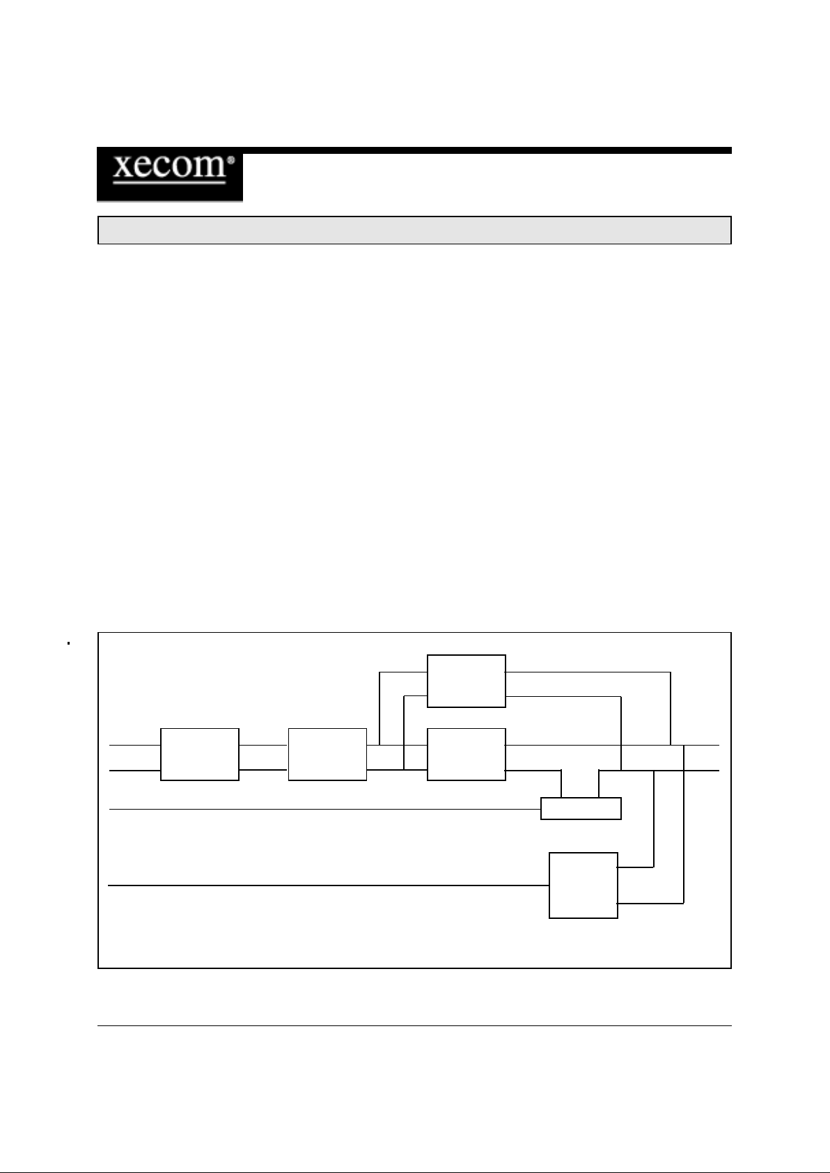
XE0016 Block Diagram
Caller ID
2/4 Wire Line Loop Current
Convertor Transforner Hold Circuit
Hookswitch
Ring
Detector
Tx
Rx
Tip
Ring
OH
\RI
XECOM (2) XE0016
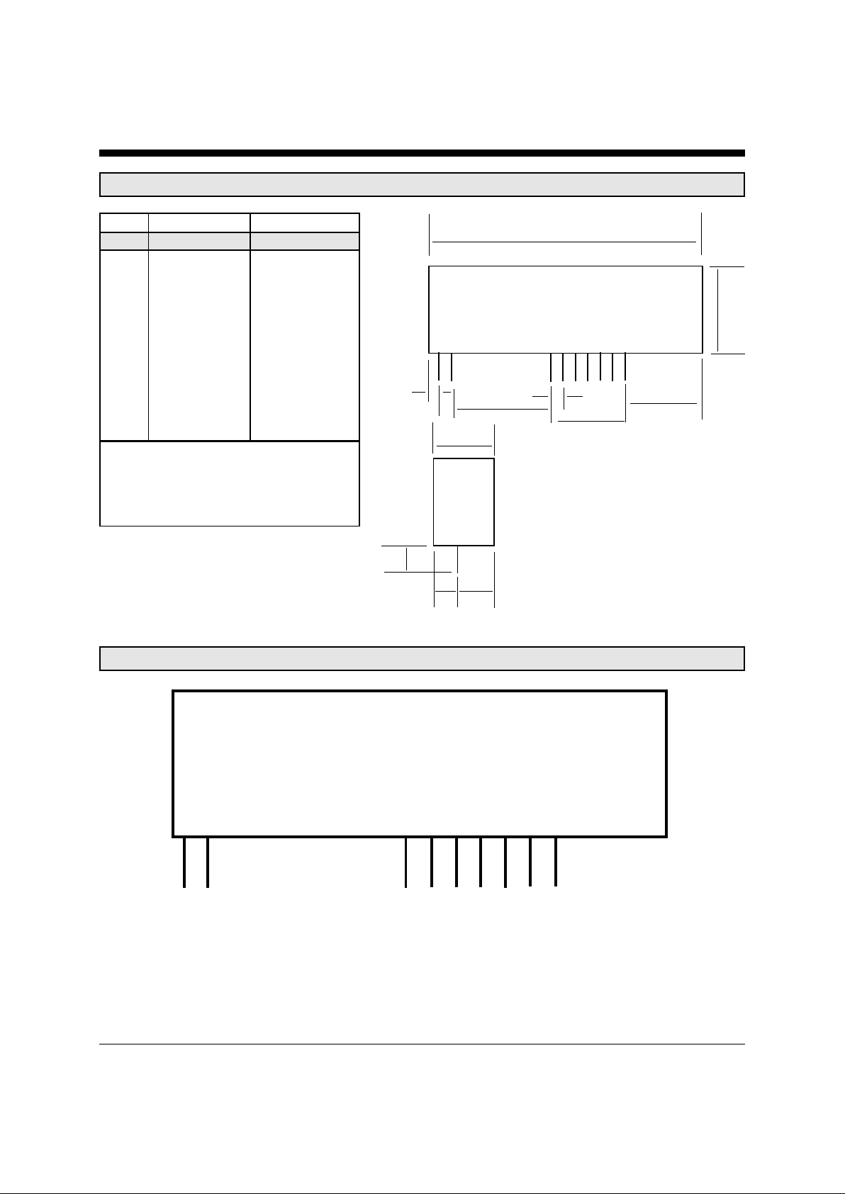
XE0016 Mechanical Specifications
Inches Millimeters
Dim Min Max Min Max
A 2.000 2.030 50.80 51.56
B 0.520 0.550 13.21 13.97
C 0.400 0.430 10.16 10.92
D 0.040 0.070 1.02 1.78
E 0.090 0.110 2.29 2.79
F 0.790 0.810 20.07 20.57
G 0.590 0.610 14.99 15.49
H 0.445 0.475 11.30 12.06
I 0.140 0.170 3.56 4.32
J 0.240 0.270 6.10 6.86
K 0.125 - 3.18 -
A
B
D
F
E
G
H
C
K
IJ
Notes:
These dimensions reflect the module’s
maximum envelope.
I/O Pins are 0.010 inches by 0.020 inches
XE0016 Pin Configuration
12 34567 89
Ring Tip OH Tx Gnd Vcc Rx \RI Vdd
XECOM (3) XE0016
XE0016 PIN DESCRIPTIONS
PIN NAME I/O DESCRIPTION
1 Ring --- Ring is one of two signals which form the telephone network connection (RJ11
Pin 4). The XE0016 is not sensitive to the polarity of the battery voltage on the
telephone line. Ring provides 1500 Volts of isolation between the telephone
line and all other circuitry.
2 Tip --- Tip provides the second connection to the telephone network (RJ11 Pin 3). Tip
also provides 1500 Volts of isolation betwen the telephone line and all other
circuits. Xecom rcommends that a minimum distance of .1 inches be
maintained between the Tip and Ring Traces and all other circuits to mainatain
the isolation barrier throughout the system.
3 OH I OH provides active high Hookswitch control. A High on OH closes the internal
relay to connect the equipment to the phone line.
4 TX I TX is the Analog input signal to the XE0016. The input impedance on TX is
typically 10 Kohms at 1800 Hz. The gain or loss of signals placed on TX shall be
no more than 1 dB. Signals on TX are referenced to ground.
5 GND --- Ground reference for the XE0016;
6 Vcc --- Vcc provides +5 Volt power to the XE0016.
7 RX O RX is the Analog output signal from the XE0016. The output impedance of RX is
typically 10 ohms at 1800 hz. The signal level on RX will be within 1 dBm of the
received signal level present on the telephone line. Signals on RX are
referenced to ground.
8 \RI O Ring Indicate, output, active low, TTL, RI provides a half-wave representation of
the Ring as it appears on the telephone line. The /RI output is referenced to
ground.
9 Vdd --- Vdd provides -5 Volt power to the XE0016.

XECOM (4) XE0016
Electrical Specifications (Vcc = +5 Volts + 10%; Vdd = -5 Volts + 10%; Ta = 0 to 70 degrees centigrade)
Parameter Conditions Min Typ Max Units
Icc Off-Hook, Vcc=5.0 Volts 2.5 4.0 milliamps
Idd Vdd = -5.0 Volts 1.0 1.5 milliamps
Transmit Insertion Loss 600 Ohm line impedance, 1000 Hz -1.0 0 1.0 dB
Receive Insertion Loss 600 Ohm line impedance, 1000 Hz -1.0 0 1.0 dB
Caller ID Insertion Loss On Hook 8.0 6.0 4.0 dB
Line Impedance 1000 Hz 540 600 660 ohms
Ring Detect Sensitivity On-Hook, Type B Ringer, must detect 38 150 Vrms
Ring Detect Peak Current Ring Voltage equals 40 Vrms 100 microamps
Ring Indicate idle Current No Ring Voltage Present 10 microamps
Ring Indicate Output Ring Signal present across Tip and Ring 0.2 0.5 Volts
Hook Switch Control (Of f-Hook) 2.0 3.0 V olts
Voltage (On-Hook) 0.2 0.5 Volts
Hook Switch Control 4 6 milliamps
Current
Loop Current DC current draw from the telephone line 0 100 milliamps
T otal Harmonic Distortion Frequency 1800 Hz, signal level -9 dBm -85 dBm
Absolute Maximum Ratings
Storage Temperature -25C to +85C
Operating Temperature Range 0C to +70C
Maximum Lead Temperature (soldering 2 seconds per wave) 260 C

XECOM (5) XE0016
XE0016 Typical Connection Diagram
o
o
o
o
o
o
o
o
o
Pin 1 Ring
Pin 2 Tip
Pin 3 OH
Pin 4 Tx
Pin 5 Gnd
Pin 6 VCC
Pin 7 Rx
Pin 8 /RI
Pin 9 VDD
10 ohms
RV1
FB1
FB1
C1 C2
RJ11
XE0016
OH
TRANSMIT
RECEIVE
RINGD
AFE
+5 Volts
10 ohms
-5 Volts
Notes:
FB1 and FB2 are ferrite beads. They work in conjunction with Capacitors C1 and C2 to eliminate EMI from the
telephone cable. Xecom recommends a TDK CB30-1812 surface mount ferrite bead because it provides over 100
ohms impedance at 100 MHz.
C1 and C2 ground any EMI signal present on Tip and Ring. Xecom recommends a Sprague 30GAT47 capacitor .
This is a 470 pFd capacitor rated for 3000 Volts. The high voltage rating is required to maintian the required
isolation barrier between the telephone line and ground.
R V1 is a solid-state protection device to reduce the likelihood of damage due to lightning strikes. RV1 works in
conjunction with the two 10 ohm resistors to protect the XE0016 circuitry. Xecom recommends the Teccor P3100
Sidactor for this function. Its typical breakover voltage of 310 volts prevents the XE0016 from being exposed to
voltage surges while being rated high enough to prevent being triggered by an incoming Ring signal.

XECOM (6) XE0016
Telephone Line Connection Information
When developing a product to be connected to the telephone line , it is necessary to use a circuit known as
a Data Access Arrangement (DAA) approved by the appropriate governmental agency. In the US this
agency is the Federal Communications Commission (FCC), while in Canada it is Industry Canada (IC).
These agencies test and approve the product to ensure that it meets their specifications, thereb y protecting
the telephone system from damage and protecting the user from high voltage transients (such as lightning
strikes) which may come down the telephone line.
The XE0016 has been designed to meet all FCC Part 68 requirements for hazardous voltage, line
impedance and leakage current. If the system transmits data, synthesized voice, or DTMF tones on the
telephone line, the user must certify that the signals transmitted meet basic FCC requirements for
maximum transmission levels, out of band energy and billing delay. Full details may be obtained from the
FCC under Part 68 of the FCC Rules and Regulations, or in Title 47 of the Code of Federal Regulations,
however the basic requirements are as follows:
1. Maximum Transmit Level
For the normal “permissive” (standard) telephone line , equipment which tr ansmits data (such as a modem)
must not exceed a transmission level of -9 dBm.
2. Out of Band Energy
Data equipment must not transmit “out of band” energy on the telephone line which exceeds the following
limits:
Frequency Range Max. Power
3995 Hz to 4005 Hz -27 dBm
4005 Hz to 12 kHz -20 dBm
12 kHz to 90 kHz -55 dBm
90 kHz to 270 kHz -55 dBm
270 kHz to 6 MHz -15 dBm
3. DTMF T ransmission Level
If the system is capable of DTMF dialing, the maximum DTMF transmission level must be less than 0 dBm
averaged over a 3 second interval.
4. Billing Delay
A delay of 2 seconds or greater is required after the time the XE0016 is taken “off hook” and before any
information is transmitted. This is required to ensure that billing information may be exchanged between
telephone company central offices without interference.
OEM’s using the XE0016 must certify to the FCC that the final system meets the requirements of Part 68
which include the criteria above as well as the high voltage protection provided by the XE0016. This is
generally accomplished through an independent testing lab which tests the System and submits the proper
paperwork to the FCC for approval. Since the XE0016 already complies with FCC Part 68 rules, this is a
relatively simple process.

XECOM (7) XE0016
Copyright, Xecom © 1999
While Xecom, Inc. has made every effort to ensure that the information presented here is accurate, Xecom will not be liable for any damages arising from errors or omission of fact. Xecom reserves the right
to modify specifications and/or prices without notice. Product mentioned herein are used for identification
purposes only and may be trademarks and/or registered trademarks of their respective companies.
Xecom
Incorporated
374 Turquoise Street, Milpitas, CA 95035
Ph:408-945 -6640 Fax:408- 942-1346
Email: info@xecom.com
Terms of Sale
Devices sold by XECOM are covered by the warranty provisions appearing in its Terms of Sale only.
XECOM makes no warranty, express, statutory, implied, or by description regarding the information set
forth herein, or regarding the freedom of the described devices from patent infringement. XECOM makes
no warranty of merchantability or fitness for any purposes. XECOM reserves the right to discontinue
production and change specifications and prices at any time and without notice. This product is intended
for use in normal commercial applications. Applications requiring extended temperature range, unusual
environmental requirements, or high reliability applications, such as military, medical life-support or lifesustaining equipment, are specifically not recommended without additional processing and authorization
by XECOM for such application.
Xecom assumes no responsibility for the use of any circuitry other than circuitry embodied in a Xecom
product. No other circuits, patents, or licenses are implied.
Life Support Policy
Xecom's products are not authorized for use as Critical Components in Life Support Devices or Systems.
Life Support Devices or Systems are devices or systems which, (a) are intended for surgical implant
into the body, or (b) support or sustain life, and whose failure to perform, when properly used in accordance with instructions provided in the labeling, can be reasonably expected to result in significant injury
to the user.
A Critical Component is any component of a life support device or system whose failure to perfor m can
be reasonably expected to cause failure of the life support device or system, or to affect its safety or effectiveness.
 Loading...