

Page 1
A
r
p
XBS204S17R-G
Schottky Barrier Diode, 2A, 40V Type
■FEATURES
Forward Voltage : VF=0.485V (TYP.)
Forward Current : I
Repetitive Peak Reverse Voltage : V
■
BSOLUTE MAXIMUM RATINGS
Ta=25℃
PARAMETER SYMBOL RATINGS UNIT
Repetitive Peak Reverse Voltage VRM 40 V
Reverse Voltage (DC) VR 40 V
Forward Current (Average) IF(AVE) 2 A
Non Continuous
Forward Surge Current
Junction Temperature Tj 125
Storage Temperature Range Tstg
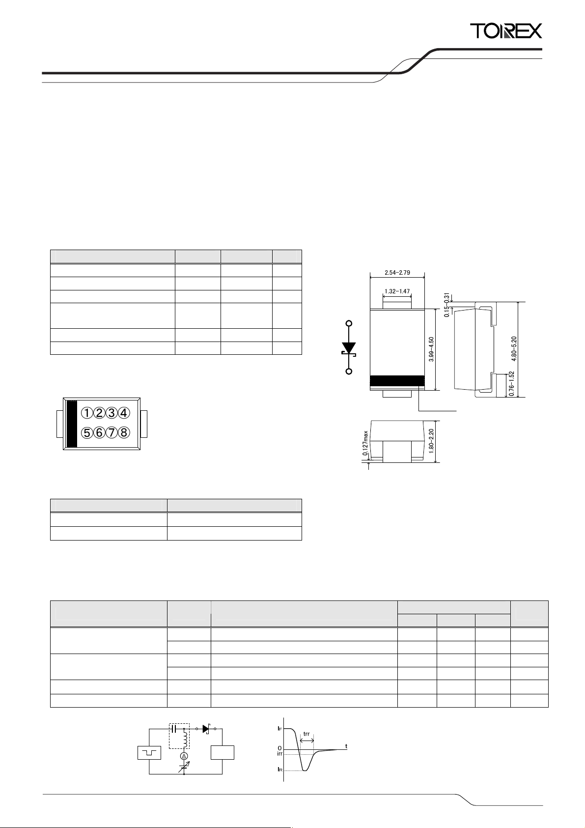
■MARKING RULE
*1
I
FSM 50 A
=2A
F(AVE)
=40V
RM
-55~+150 ℃
℃
ETR1612-002a
■APPLICATIONS
●Rectification
●Protection against reverse connection of battery
■PACKAGING INFORMATION
①②③④⑤⑥: 204S17(Product Number)
⑦⑧ : Assembly Lot Number
■PRODUCT NAME
PRODUCT NAME DEVICE ORIENTATION
XBS204S17R-G SMA (Halogen & Antimony free)
XBS204S17R SMA
* The “-G” suffix indicates that the products are Halogen and Antimony free as well as being fully RoHS compliant.
* The device orientation is fixed in its embossed tape pocket.
SMA
Cathode Bar
Unit: mm
■ELECTRICAL CHARACTERISTICS
PARAMETER SYMBOL TEST CONDITIONS
Forward Voltage
Reverse Current
Inter-Terminal Capacity Ct VR=1V , f=1MHz - 180 - pF
Reverse Recovery Time*2 trr IF=IR=10mA , irr=1mA - 51 - ns
*2:trr measurement circuit
Pulse Generatrix
Bias
VF1
V
IR1 VR=20V - 2.5 -
R2 V
I
I
=200μA
F
F2 I
=2A - 0.485 0.54 V
F
=40V 6 200
R
Device Unde
Oscillosco
test
e
MIN. TYP. MAX.
LIMITS
- 0.15 - V
Ta=25℃
UNIT
μA
μA
1/3
Page 2
XBS204S17R-G
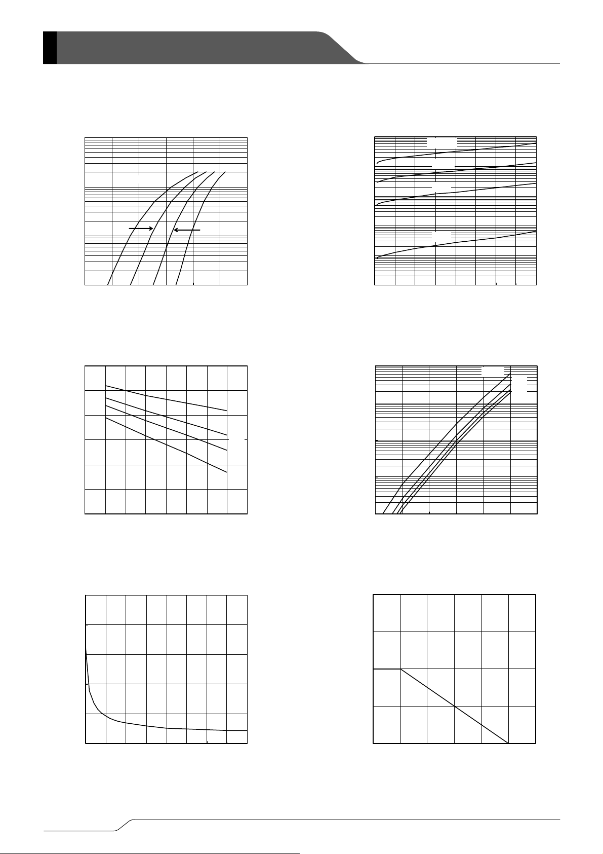
■TYPICAL PERFORMANCE CHARACTERISTICS
(1) Forward Current vs. Forward Voltage (2) Reverse Current vs. Reverse Voltage
10
(A)
F
1
Ta=125℃
-25℃
10000
1000
(uA)
R
Ta=125℃
100℃
75℃
100
Reverse Current: IR (μA)
10
25℃
Reverse Current I
1
0.1
0 10203040
Reverse Voltage V
R
(V)
75℃
Forward Current I
Forward Current: IF (A)
0.1
0.01
0 0.2 0.4 0.6
Forward Voltage: VF (V) Reverse Voltage: VR (V)
Forward Voltage V
F
(V)
25℃
(3) Forward Voltage vs. Operating Temperature (4) Reverse Current vs. Operating Temperature
0.6
(V)
F
0.4
I
=2A
10000
1000
(uA)
R
VR=40V
20V
10V
5V
0.2
Forward Voltage V
Forward Voltage: VF (V)
0.0
-50 0 50 100 150
Operating Temperature: Ta (℃) Operating Temperature: Ta (℃)
Operating Temperature Ta (℃)
1A
0.5A
0.1A
Reverse Current: IR (μA)
100
10
Reverse Current I
1
0 50 100 150
Operating Temperature Ta (℃)
(5) Inter-Terminal Capacity vs. Reverse Voltage (6) Average Forward Current vs. Operating Temperature
500
400
4.0
(A)
AV
3.0
300
2.0
200
1.0
Average Forward Current IF
Average Forward Current: IFAV (A)
0.0
0 50 100 150
Inter-Terminal Capacity Ct (pF)
Inter-Terminal Capacity: Ct (pF)
100
0
0 10203040
2/3
Rever se Volt age V
R
(V)
Operating Temperature Ta (℃)
Operating Temperature: Ta (℃) Reverse Voltage: VR (V)
Page 3

XBS204S17R-G
1. The products and product specifications contained he rein are subject to change without
notice to improve performance characteristics. Consult us, or our representatives
before use, to confirm that the information in this datasheet is up to date.
2. We assume no responsibility for any infringement of patents, patent rights, or other
rights arising from the use of any information and circuitry in this datasheet.
3. Please ensure suitable shipping controls (including fail-safe designs and aging
protection) are in force for equipment employing products listed in this datasheet.
4. The products in this datasheet are not developed, designed, or approved for use with
such equipment whose failure of malfunction can be reasonably expected to directly
endanger the life of, or cause significant injury to, the user.
(e.g. Atomic energy; aerospace; transport; combustion and associated safety
equipment thereof.)
5. Please use the products listed in this datasheet within the specified ranges.
Should you wish to use the products under conditions exceeding the specifications,
please consult us or our representatives.
6. We assume no responsibility for damage or loss due to abnormal use.
7. All rights reserved. No part of this datasheet may be copied or reproduced without the
prior permission of TOREX SEMICONDUCTOR LTD.
3/3
 Loading...