

Page 1
INTEGRATED CIRCUITS
XA-SCC
CMOS 16-bit communications
microcontroller
Preliminary specification
Supersedes data of 1999 Feb 23
IC25 Data Handbook
1999 Mar 29
Page 2

Philips Semiconductors Preliminary specification
XA-SCCCMOS 16-bit communications microcontroller
GENERAL DESCRIPTION
The XA-SCC device is a member of Philips’ XA (eXtended
Architecture) family of high performance 16-bit single-chip
microcontrollers.
The XA-SCC includes a complete onboard DRAM controller capable
of supporting up to 32MegaBytes of DRAM.
The XA-SCC device combines many powerful communications
oriented peripherals on one chip. 4 Full Function SCC’s, 8 DMA
channels (2 per SCC), hardware autobaud up to 921.6Kbps, IDL
TDM interface, two timers/counters, 1 watchdog timer, and multiple
general purpose I/O ports. It is suited for many high performance
embedded communications functions, including ISDN terminal
adaptors and Asynchronous Muxes.
SPECIFIC FEATURES OF THE XA-SCC
•3.3V to 5.5V operation to 30MHz over the industrial temperature
range, available in 100 pin LQFP package.
•4 onboard SCC’s for 2B+D plus Asynch port, or any combination
of 4 sync/async ports. Industry standard IDL and SCP interfaces
for glueless connection to U-Chip or S/T chip. Sync data rates to
4Mbps. Asynch data rates to 921.6Kbps with/without autobaud.
•Complete onboard DRAM controller supports 5 banks of up to
8MBytes each. Interfaces without glue chips to most industry
standard DRAMs.
•Memory controller also generates 6 chip selects to support
SRAM, ROM, Flash, EPROM, peripheral chips, etc. without
external glue.
•Supports off-chip addressing up to 32 MB (2 x 2**24 address
spaces) in Harvard architecture, or 16MB in unified memory
configuration.
•A clock output reference “ClkOut” is added to simplify external bus
interfacing.
•High performance 8-channel DMA Controller offloads the CPU for
moving data to/from SCC’s and memory .
•Two standard counter/timers with enhanced features (same as
XA-G3 T0, T1). Both timers have a toggle output capability.
•Watchdog timer .
•Seven standard software interrupts, plus four High Priority
Software Interrupts, plus 7 levels of Hardware Event Interrupts.
•Active low reset output pin indicates all internal reset occurrences
(watchdog reset and the RESET instruction). A reset source
register allows program determination of the cause of the most
recent reset.
•32 General Purpose I/O pins, each with 4 programmable output
configurations.
•Power saving operating modes: Idle and Power-Down. Wake-Up
from power-down via an external interrupt is supported.
ORDERING INFORMATION
ROMless Only TEMPERATURE RANGE °C AND PACKAGE FREQ (MHz) PACKAGE DRAWING NUMBER
PXASCCKFBE –40 to +85, 100-pin Low Profile Quad Flat Pkg. (LQFP) 30 SOT407-1
NOTE:
1. K=30MHz, F = (–40 to +85 °C), BE = LQFP
1999 Mar 29
2
Page 3

Philips Semiconductors Preliminary specification
XA-SCCCMOS 16-bit communications microcontroller
PIN CONFIGURATION
VSS
VDD
CD1_Int2
Int0
P2.0_RxD3
P2.1_TxD3
P2.2_RTClk3
P2.3_ComClk_TRClk3
P2.4_CD3
P2.5_CTS3
P2.6_RTS3
P2.7_Sync3_BRG3
VSS
VDD
P0.0_Sync0_BRG0_SDS2
P0.1_RTS0_L1RQ
P0.2_CTS0_L1GR
P0.3_CD0_L1SY1
P0.4_TRClk0_SDS1
P0.5_RTClk0_L1Clk
TxD0_L1TxD
RxD0_L1RxD
SCPClk
P0.6_SCPTx
P0.7_SCPRx
P1.7_BRG2_Sync2
75
76
77
78
79
80
81
82
83
84
85
86
87
88
89
90
91
92
93
94
95
96
97
98
99
100
1VSS
P1.6_RTS2
P1.5_CTS2
P1.4_CD2
72
73
74
P1.3_TRClk2
P1.2_RTClk2
70
71
MOLD MARK
P1.1_TxD2
P1.0_RxD2
68
69
P3.6_TxD1
P3.5_RxD1
P3.7_Int1_TRClk1
67
P3.4_CTS1
64
65
66
P3.3_Timer1_BRG1_Sync1
VDD
XTALOUT
61
62
63
XA-SCC
PLASTIC LOW PROFILE QUAD FLAT PACKAGE (LQFP)
Top View
PIN INDEX
9
8
7
6
5
4
3
2
A0A1A2A3A4A5A6
VDD
11
12
10
A9 (A0_A18)
A7 (A21_A22)
A8 (A19_A20)
14
13
A11 (A2)
A10 (A1)
15
A12 (A3)
XTALIN
VSS
59
60
17
16
A13 (A4)
A14 (A5)
P3.2_Timer0_ResetOut
P3.1_CS5_RAS5_RTS1
P3.0_CS4_RAS4_RTClk1
56
57
58
MOLD MARK
20
19
18
VSS
VDD
A15 (A6_A22)
WAIT_Size16
BLE_CASL
BHE_CASH
Reset_In
52
53
54
55
24
23
22
21
A18
A19
A16 (A7_A20_A21)
A17 (A8_A18_A19)
OE
51
25
D0
50
49
48
47
46
45
44
43
42
41
40
39
38
37
36
35
34
33
32
31
30
29
28
27
26
WE
CS0
CS1_RAS1
CS2_RAS2
CS3_RAS3
ClkOut
VSS
VDD
D15
D14
D13
D12
D11
D10
D9
D8
D7
D6
D5
D4
D3
VDD
VSS
D2
D1
NOTE:
Address lines output during various DRAM CAS cycles are shown in parentheses.
See DRAM controller for details.
1999 Mar 29
3
SU01120
Page 4

Philips Semiconductors Preliminary specification
XA-SCCCMOS 16-bit communications microcontroller
LOGIC SYMBOL
V
V
DD
SS
MISC. SCC1 PORT3
Int2
CS4, RAS4
CS5, RAS5
ResetOut, Timer0
Timer1
Int1
Int0
CD1
RTClk1
RTS1
BRG1, Sync1
CTS1
RxD1
TxD1
TRClk1
3.0
3.1
3.2
3.3
3.4
3.5
3.6
3.7
XTAL1
XTAL2
CS3, RAS3
CS2, RAS2
CS1, RAS1
CS0
L1TxD
L1RxD
L1RQ
L1GR
L1SY1
SDS1
L1Clk
SCC3
RxD3
TxD3
RTClk3
ComClk, TRClk3
CD3
CTS3
RTS3
BRG3, Sync3
SCC2
RxD2
TxD2
RTClk2
TRClk2
CD2
CTS2
RTS2
BRG2, Sync2
TxD0
RxD0
BRG0, Sync0
RTS0
CTS0
CD0
TRClk0
RTClk0
PORT2
2.0
2.1
2.2
2.3
2.4
2.5
2.6
2.7
PORT1
1.0
1.1
1.2
1.3
1.4
1.5
1.6
1.7
PORT0SCC0IDL
0.0SDS2
0.1
0.2
0.3
0.4
0.5
A19 – A0 ( DRAM A22 – A0)
D15 – D0
ClkOut
CASH, BHE
CASL, BLE
OE
WE
Wait, Size16
ResetIn
1999 Mar 29
SCPTx
SCPRx
SCPClk
0.6
0.7
SU01121
4
Page 5

Philips Semiconductors Preliminary specification
XA-SCCCMOS 16-bit communications microcontroller
BLOCK DIAGRAM
XA CPU
EXTERNAL
MEMORY
and I/O
BUS
NOTE:
Main Communications Data paths shown in bold.
MIF and
DRAM
CONTROLLER
DMA
CHANNELS
x8
INTERRUPT
CONTROLLER
AUTOBAUD
SCCs x4
2047
v.54
x2
256 BYTES
RAM
x4
IDL
INTERFACE
Figure 1. XA-SCC Block Diagram
RESET
CONTROL &
STATUS
SCP
INTERFACE
TIMERS 0,1
WATCHDOG
TIMER
PORTS and
PIN
FUNCTION
MUX
SCP PORT
GPIO
IDL and
NMSI
PORTS
SU01122
1999 Mar 29
5
Page 6
Philips Semiconductors Preliminary specification
XA-SCCCMOS 16-bit communications microcontroller
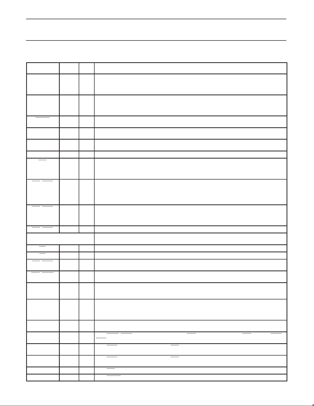
PIN DESCRIPTIONS
MNEMONIC
V
SS
V
DD
ResetIn 55 I Reset: A low on this pin resets the microcontroller, causing I/O ports and peripherals to take on their
WAIT/Size16 52 I Wait/Size16: During Reset, this input determines bus size for boot device (1 = 16 bit boot device,
XTALIn 60 I Crystal 1: Input to the inverting amplifier used in the oscillator circuit and input to the internal clock
XTALOut 61 I Crystal 2: Output from the oscillator amplifier.
CS0 49 O Chip Select 0: This output provides the active low chip select to the boot device (usually ROM or
CS1_RAS1 48 O Chip Select 1 , RAS 1: Chip selects 1 through 5 come out of reset disabled. They can be programmed
CS2_RAS2 47 O CS2 , RAS 2: Active low chip selects CS1 through CS5 come out of reset disabled. They can be
CS3_RAS3 46 O CS3, RAS 3: See chip select 2 for description.
see pins 56,57 for 2 more chip
WE 50 O Write Enable: Goes active low during all bus write cycles only.
OE 51 O Output Enable: Goes active low during all bus read cycles only.
BLE_CASL 54 O Byte Low Enable or CAS_Low_Byte: Goes active low during all bus cycles that access D7–D0, read
BHE_CASH 53 O Byte High Enable or CAS_High_Byte: Goes active low during all bus cycles that access D15–D8,
ClkOut 45 O Clock Output: This pin outputs a buffered version of the internal CPU clock. The clock output may be
A19–A0 24–21,
D15–D0 42–30,
1
P0.0
1
P0.1
1
P0.2
1
P0.3
1, 2
P0.4
LQFP
PIN NO.
1, 19,
TYPE NAME AND FUNCTION
I Ground: 0V reference.
28, 44,
59, 76,
88
2, 20,
I Power Supply: This is the power supply voltage for normal, idle, and power down operation.
29, 43,
62, 77,
89
default states, and the processor to begin execution at the address contained in the reset vector.
0 = 8 bit.) During normal operation this is the Wait input (1 = Wait, 0 = Proceed.)
generator circuits.
Flash.) It cannot be connected to DRAM. From reset, it is enabled and mapped to an address range
based at 000000h. It can be remapped to a higher base in the address map (see the Memory Interface
chapter in the XA-SCC User Manual.)
to function as normal chip selects, or as RAS strobes to DRAM. CS1 can be “swapped” with CS0
(see the SWAP operation and control bit in the Memory Controller chapter of the XA-SCC
User Manual.) CS1 is usually mapped to be based at 000000h eventually, but is capable of being based
anywhere in the 16MB space.
programmed to function as normal chip selects, or as RAS strobes to DRAM. CS2 through CS5 are
not used with the “SWAP” operation (see Memory Controller chapter in the XA-SCC User Manual.)
They are mappable to any region of the 16MB address space.
selects
or write, Generic or DRAM. Functions as CAS during DRAM cycles.
read or write, Generic or DRAM. Functions as CAS during DRAM cycles.
used in conjunction with the external bus to synchronize WAIT state generators, etc. The clock output
may be disabled by software. WARNING: The capacitive loading on this output must not exceed 40pF.
O Address[19:0]: These address lines output a19–a0 during generic (SRAM etc) bus cycles. DRAMs are
18–3
connected only to pins 22,21, 18–10 (pins A17 to A7; see User Manual MIF Chapter for connecting
various DRAM sizes); the appropriate address values are multiplexed onto these 11 pins for RAS and
CAS during DRAM bus cycles.
I/O Data[15:0]: Bi-directional data bus, D15–D0.
27–25
90 I/O P0.0_Sync0_BRG0_SDS2: Port 0 Bit 0, or SCC0 Sync input or output, or SCC0 BRG output, or SCC0
TxClk output, or IDL SDS2 output.
91 I/O P0.1_RTS0_L1RQ: Port0 Bit1 , or SCC0 RTS (Request to send) output, or IDL L1RQ (D Channel
Request) output.
92 I/O P0.2_CTS0_L1GR: Port 0 Bit2, or SCC0 CTS (Clear to Send) input or IDL L1GR (D Channel Grant)
input
93 I/O P0.3_CD0_L1SY1: Port 0 Bit 3, or SCC0 Carrier Detect input, or IDL Sync input.
94 I/O P0.4_TRClk0_SDS1: Port 0 Bit 4, or SCC0 TR clock input, or IDL SDS1 output.
1999 Mar 29
6
Page 7
Philips Semiconductors Preliminary specification
XA-SCCCMOS 16-bit communications microcontroller
MNEMONIC NAME AND FUNCTIONTYPE
1, 2
P0.5
1
P0.6
1
P0.7
LQFP
PIN NO.
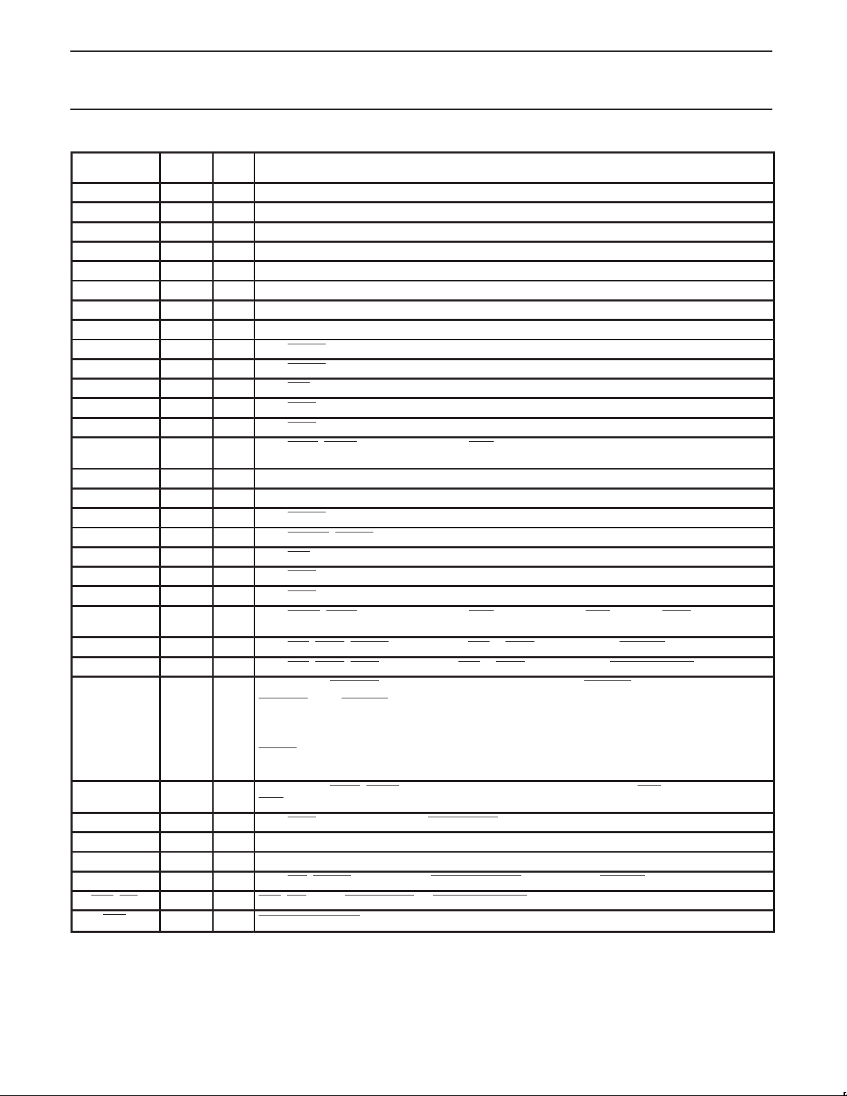
95 I/O P0.5_RTClk0_L1Clk: Port 0 Bit 5, or SCC0 RT clock input, or IDL Clock input.
99 I/O P0.6_SCPTx: Port 0 Bit 6, or SCP interface Transmit data output.
100 I/O P0.7_SCPRx: Port 0 Bit 7, or SCP interface Receive data input.
TxD0_L1TxD 96 O TxD0_L1Txd: Transmit data for SCC0 in NMSI mode, or for IDL bus
RxD0_L1RxD 97 I RxD0_L1Rxd: Receive data for SCC0 in NMSI mode, or for IDL bus
SCPClk 98 O SCPClk: This output provides the gated clock for the SCP bus.
P1.0 68 I/O P1.0_RxD2: Port 1 Bit 0, or SCC2 RxD input
P1.1 69 I/O P1.1_TxD2: Port 1 Bit 1, or SCC2 TxD output
2
P1.2
P1.3
2
70 I/O P1.2_RTClk2: Port 1 Bit 2, or SCC2 RT Clock input
71 I/O P1.3_TRClk2: Port 1 Bit 3, or SCC2 TR Clock input
P1.4 72 I/O P1.4_CD2: Port 1 Bit 4, or SCC2 Carrier Detect input
P1.5 73 I/O P1.5_CTS2: Port 1 Bit 5, or SCC2 Clear To Send input
P1.6 74 I/O P1.6_RTS2: Port 1 Bit 6, or SCC2 Request To Send output
P1.7 75 I/O P1.7_BRG2_Sync2: Port 1 Bit 7, or SCC2 Sync input or output, or BRG output, or TxClk output (see
SCC clocks diagrams in User Manual Chp 5)
P2.0 80 I/O P2.0_RxD3: Port 2 Bit 0, or SCC3 Rx Data input
P2.1 81 I/O P2.1_TxD3: Port 2 Bit 1, or SCC3 Tx Data output
2
P2.2
P2.3
2
82 I/O P2.2_RTClk3: Port 2 Bit 2, or SCC3 RT Clock input
83 I/O P2.3_ComClk_TRClk3: Port 2 Bit 3, or SCC3 TR Clock input
P2.4 84 I/O P2.4_CD3: Port 2 Bit 4, or SCC3 Carrier Detect input
P2.5 85 I/O P2.5_CTS3: Port 2 Bit 5, or SCC3 Clear To Send input
P2.6 86 I/O P2.6_RTS3: Port 2 Bit 6, or SCC3 Request To Send output
P2.7 87 I/O P2.7_Sync3_BRG3: Port 2 Bit 7, or SCC3 Sync input or output, or BRG output, or TxClk output (see
SCC clocks diagrams in User Manual Chp 5)
2
P3.0
56 I/O P3.0_CS4_RAS4_RTClk1: Port 3 Bit 0, or CS4 or RAS4 output, or SCC1 RT Clock input
P3.1 57 I/O P3.1_CS5_RAS5_RTS1: Port 3 Bit 1, or CS5 or RAS5 output, or SCC1 Request To Send output
P3.2 58 I/O P3.2_Timer0_ResetOut: Port 3 Bit 2, or Timer0 input or output, or ResetOut output.
ResetOut
: If the ResetOut function is selected, this pin outputs a low whenever the XA-SCC processor
is reset by an internal source (watchdog reset or the RESET instruction.) WARNING: Unlike the other
31 GPIO pins, during power up reset, this pin can output a strongly driven low pulse. The duration of this
low pulse ranges from 0ns to 258 system clocks, starting at the time that V
pin does not affect this pulse.
ResetIn
is valid. The state of the
CC
When used as GPIO, this pin can also be driven low by software without resetting the XA-SCC.
P3.3 63 I/O P3.3_Timer1_BRG1_Sync1: Port 3 Bit 3, or Timer1 input or output, or SCC1 BRG output, or SCC1
Sync input or output
P3.4 64 I/O P3.4_CTS1: Port 3 Bit 4, or SCC1 Clear To Send input
P3.5 65 I/O P3.5_RxD1: Port 3 Bit 5, or SCC1 Receive Data input
P3.6 66 I/O P3.6_TxD1: Port 3 Bit 6, or SCC1 Transmit Data output
2
P3.7
67 I/O P3.7_Int1_TRClk1: Port 3 Bit 7, or External Interrupt1 input, or SCC1 TR Clock input
CD1_Int2 78 I CD1_Int2: SCC1 Carrier Detect, or External Interrupt 2
Int0
79 I External Interrupt 0
NOTES:
1. See XA-SCC User Guide “Pins Chapter” for how to program selection of pin functions.
2. RTClk input is usually used for Rx Clock if an external clock is needed, but can be used for either Rx or Tx or both. TRClk is usually used for
Tx Clock, but can be used for Rx or Tx or both.
1999 Mar 29
7
Page 8
Philips Semiconductors Preliminary specification
BTRL = 40h in that order. Follow these two writes with five NOPS. This is not the
XA-SCCCMOS 16-bit communications microcontroller
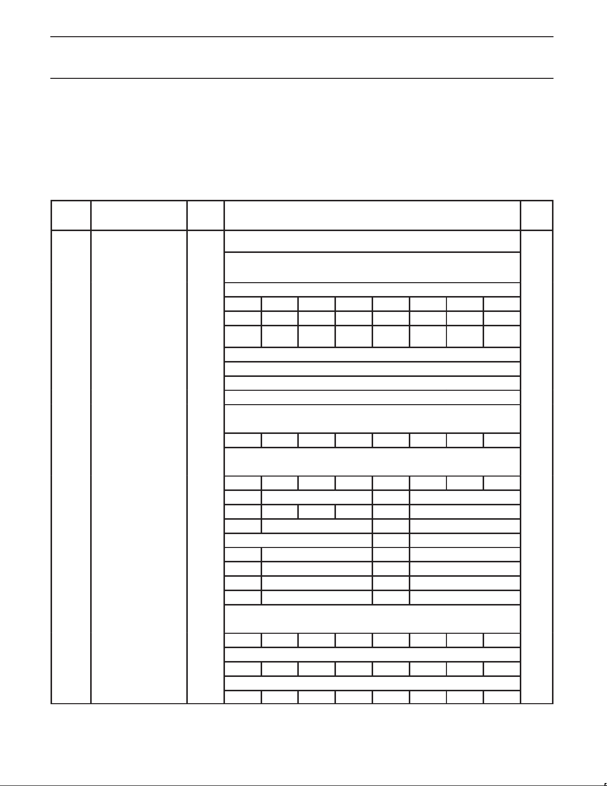
CONTROL REGISTER OVERVIEW
There are two types of control registers in the XA-SCC, these are
SFRs (Special Function Registers), and MMRs (Memory Mapped
Registers.) The SFR registers, with the exception of MRBL, MRBH,
MICFG, BCR, BRTH, BRTL, and RSTSRC are the standard XA core
registers. See WARNINGs about BCR, BRTH, and BRTL in the
Table below.
SFRs are accessed by “direct addressing” only (see IC25 XA User
Manual for direct addressing.) The MMRs are specific to the
XA-SCC on board peripherals, and can be accessed by any
addressing mode that can be used for off chip data accesses. The
MMRs are implemented in a relocatable block. See the MIF chapter
in the XA-SCC User Manual for details on how to relocate the
MMRs by writing a new base address into the MRBL and MRBH
(MMR Base Low and High) registers.
Table 1. Special Function Registers (SFR)
SFR
NAME DESCRIPTION
BCR Bus Configuration Reg
BTRH Bus Timing Reg High 469h WARNING—Immediately after reset, always write BTRH = 51h, followed by writing
BTRL Bus Timing Reg Low 468h
MRBL# MMR Base Address Low 496h MA15 MA14 MA13 MA12 – – – MRBE x0h
MRBH# MMR Base Address High 497h MA23 MA22 MA21 MA20 MA19 MA18 MA17 MA16 xx
MICFG# ClkOut Tri-St Enable
CS Code Segment 443h 00h
DS Data Segment 441h 00h
ES Extra Segment 442h 00h
RESERVED—see warning
1 = Enabled
Address
46Ah WARNING—Never write to the BCR register in the XA-SCC part—it is initialized to
499h – – – – – – – CLKOE 01h
1, 2, 3
BIT FUNCTIONS AND ADDRESSES
MSB LSB
07h, the only legal value. This is not the same as for other XA derivatives.
same as for other XA derivatives.
RESET
VALUE
07h
FFh
EFh
33F 33E 33D 33C 33B 33A 339 338
IEH* Interrupt Enable High 427h EHSWR3 EHSWR2 EHSWR1 EHSWR0 ESCP EAuto ESC23 ESC01 00h
337 336 335 334 333 332 331 330
IEL* Interrupt Enable Low 426h EA EDMAH EDMAL EX2 ET1 EX1 ET0 EX0 00h
IPA0 Interrupt Priority A0 4A0h – PT0 – PX0 00h
IPA1 Interrupt Priority A1 4A1h – PT1 – PX1 00h
IPA2 Interrupt Priority A2 4A2h – PDMAL – PX2 00h
IPA3 Interrupt Priority A3 4A3h Reserved – PDMAH 00h
IPA4 Interrupt Priority A4 4A4h – PSC23 – PSC01 00h
IPA5 Interrupt Priority A5 4A5h – PSCP – PAutoB 00h
IPA6 Interrupt Priority A6 4A6h – PHSWR1 – PHSWR0 00h
IPA7 Interrupt Priority A7 4A7h – PHSWR3 – PHSWR2 00h
387 386 385 384 383 382 381 380
P0* Port 0 430h FFh
38F 38E 38D 38C 38B 38A 389 388
P1* Port 1 431h FFh
397 396 395 394 393 392 391 390
P2* Port 2 432h FFh
1999 Mar 29
8
Page 9
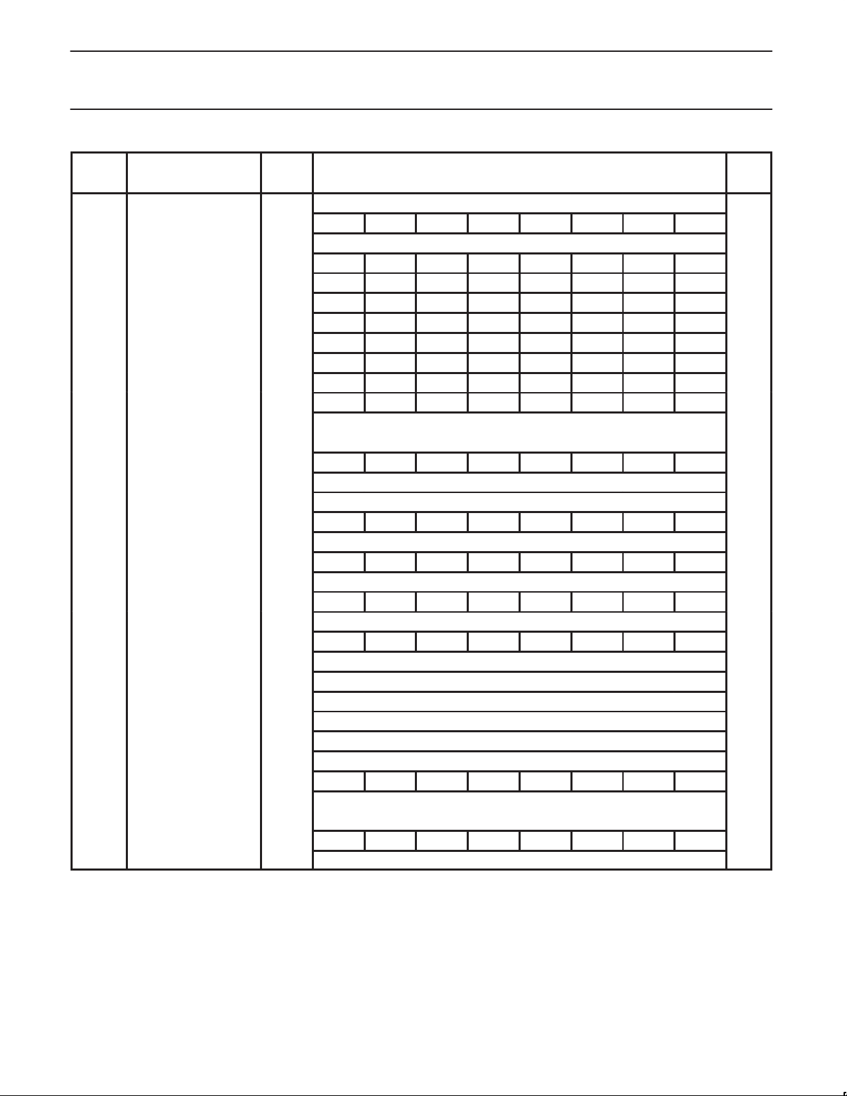
Philips Semiconductors Preliminary specification
XA-SCCCMOS 16-bit communications microcontroller
SFR
NAME
P3* Port 3 433h FFh
P0CFGA Port 0 Configuration A 470h Note 4
P1CFGA Port 1 Configuration A 471h Note 4
P2CFGA Port 2 Configuration A 472h Note 4
P3CFGA Port 3 Configuration A 473h Note 4
P0CFGB Port 0 Configuration B 4F0h Note 4
P1CFGB Port 1 Configuration B 4F1h Note 4
P2CFGB Port 2 Configuration B 4F2h Note 4
P3CFGB Port 3 Configuration B 4F3h Note 4
PCON* Power Control Reg 404h – – – – – – PD IDL 00h
PSWH* Program Status Word High 401h SM TM RS1 RS0 IM3 IM2 IM1 IM0 Note 5
PSWL* Program Status Word Low 400h C AC – – – V N Z Note 5
PSW51* 80C51 compatible PSW 402h C AC F0 RS1 RS0 V F1 P Note 6
DESCRIPTION
Address
MSB LSB
39F 39E 39D 39C 39B 39A 399 398
227 226 225 224 223 222 221 220
20F 20E 20D 20C 20B 20A 209 208
207 206 205 204 203 202 201 200
217 216 215 214 213 212 211 210
BIT FUNCTIONS AND ADDRESSES
RESET
VALUE
RSTSRC Reset Source Reg 463h ROEN – – – – R_WD R_CMD R_EXT Note 7
RTH0 Timer 0 Reload High 455h 00h
RTH1 Timer 1 Reload High 457h 00h
RTL0 Timer 0 Reload Low 454h 00h
RTL1 Timer 1 Reload Low 456h 00h
SCR System Configuration Reg 440h – – – – PT1 PT0 CM PZ 00h
21F 21E 21D 21C 21B 21A 219 218
SSEL* Segment Selection Reg 403h ESWEN R6SEG R5SEG R4SEG R3SEG R2SEG R1SEG R0SEG 00h
1999 Mar 29
9
Page 10

Philips Semiconductors Preliminary specification
XA-SCCCMOS 16-bit communications microcontroller
SFR
NAME
SWE Software Interrupt Enable 47Ah – SWE7 SWE6 SWE5 SWE4 SWE3 SWE2 SWE1 00h
SWR* Software Interrupt Request 42Ah – SWR7 SWR6 SWR5 SWR4 SWR3 SWR2 SWR1 00h
TCON* T imer 0/1 Control 410h TF1 TR1 TF0 TR0 IE1 IT1 IE0 IT0 00h
TH0 Timer 0 High 451h 00h
TH1 Timer 1 High 453h 00h
TL0 Timer 0 Low 450h 00h
TL1 Timer 1 Low 452h 00h
TMOD Timer 0/1 Mode 45Ch GATE C/T M1 M0 GATE C/T M1 M0 00h
TSTAT* Timer 0/1 Extended Status 411h – – – – – T1OE – T0OE 00h
WDCON* Watchdog Control 41Fh PRE2 PRE1 PRE0 – – WDRUN WDTOF – Note 8
WDL Watchdog Timer Reload 45Fh 00h
WFEED1 W atchdog Feed 1 45Dh xx
WFEED2 W atchdog Feed 2 45Eh xx
DESCRIPTION
Address
MSB LSB
357 356 355 354 353 352 351 350
287 286 285 284 283 282 281 280
28F 28E 28D 28C 28B 28A 289 288
2FF 2FE 2FD 2FC 2FB 2FA 2F9 2F8
BIT FUNCTIONS AND ADDRESSES
RESET
VALUE
NOTES:
* SFRs marked with an asterisk (*) are bit addressable.
# SFRs marked with a pound sign (#) are additional SFR registers specific to the XA-SCC.
1. The XA-SCC implements an 8-bit SFR bus, as stated in Chapter 8 of the IC25 Data Handbook XA User Guide. All SFR accesses must be
8-bit operations. Attempts to write 16 bits to an SFR will actually write only the lower 8 bits. Sixteen bit SFR reads will return undefined data
in the upper byte.
2. Unimplemented bits in SFRs are X (unknown) at all times. Ones should not be written to these bits since they may be used for other
purposes in future XA derivatives. The reset value shown for these bits is 0.
3. The XA guards writes to certain bits (typically interrupt flags) that may be written by a peripheral function. This prevents loss of an interrupt
or other status if a bit was written directly by a peripheral action between the read and write of an instruction that performs a
read-modify-write operation. XA-SCC SFR bits that are guarded in this manner are: TF1, TF0, IE1, and IE0 (in TCON), and WDTOF (in
WDCON).
4. Port configurations default to quasi-bidirectional when the XA begins execution after reset. Thus all PnCFGA registers will contain FFh
and PnCFGB register will contain 00h. See warning in XA-SCC User Manual about P3.2_Timer0_ResetOut
pin during first 258 clocks after
power up. Basically, during this period, this pin may output a strongly driven low pulse. If the pulse does occur, it will terminate in a
transition to high at a time no later than the 259th system clock after valid VCC power up.
5. SFR is loaded from the reset vector.
6. F1, F0, and P reset to 0. All other bits are loaded from the reset vector.
7. The RSTSRC register reflects the cause of the last XA reset. One bit will be set to 1, the others will be 0. RSTSRC[7] enables the ResetOut
function; 1 = Enabled, 0 = Disabled. See XA-SCC User Manual for details; RSTSRC[7] differs in function from most other XA derivatives.
8. The WDCON reset value is E6 for a Watchdog reset, E4 for all other reset causes.
1999 Mar 29
10
Page 11
Philips Semiconductors Preliminary specification
XA-SCCCMOS 16-bit communications microcontroller
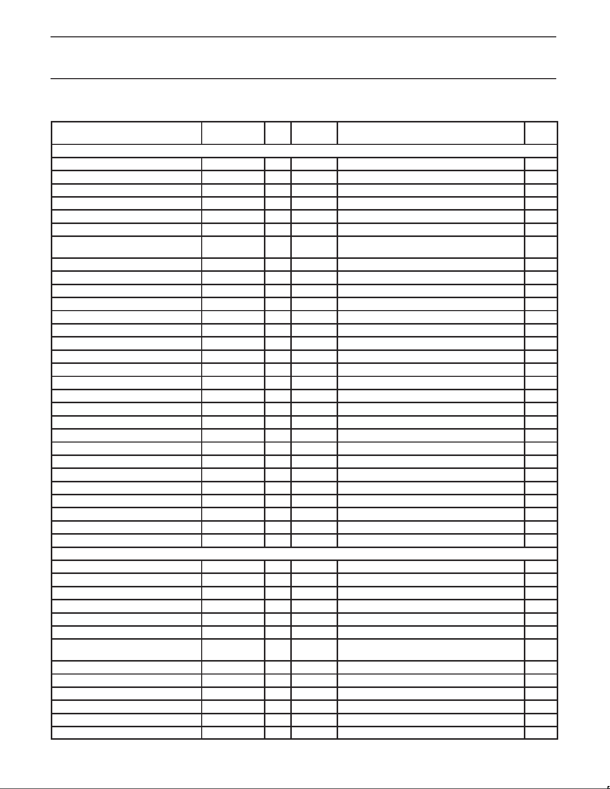
Table 2. Memory Mapped Registers
MMR Name
SCC0 Write Register 0 R/W 8 800h Command register 00h
SCC0 Write Register 1 R/W 8 802h Tx/Rx Interrupt & data transfer mode xx
SCC0 Write Register 2 R/W 8 804h Extended Features Control xx
SCC0 Write Register 3 R/W 8 806h Receive Parameter and Control 00h
SCC0 Write Register 4 R/W 8 808h Tx/Rx misc. parameters & mode 00h
SCC0 Write Register 5 R/W 8 80Ah Tx. parameter and control 00h
SCC0 Write Register 6 R/W 8 80Ch Sync character or SDLC address field or Match
SCC0 Write Register 7 R/W 8 80Eh Sync character or SDLC flag or Match Character 1 xx
SCC0 Write Register 8 R/W 8 810h Transmit Data Buffer xx
SCC0 Write Register 9 R/W 8 812h Master Interrupt control xx
SCC0 Write Register 10 R/W 8 814h Misc. Tx/Rx control register 00h
SCC0 Write Register 1 1 R/W 8 816h Clock Mode Control xx
SCC0 Write Register 12 R/W 8 818h Lower Byte of Baud rate time constant 00h
SCC0 Write Register 13 R/W 8 81Ah Upper Byte of Baud rate time constant 00h
SCC0 Write Register 14 R/W 8 81Ch Misc. Control bits xx
SCC0 Write Register 15 R/W 8 81Eh External/Status interrupt control f8h
SCC0 Write Register 16 R/W 8 828h Match Character 2 (WR16) 00h
SCC0 Write Register 17 R/W 8 82Ah Match Character 3 (WR17) 00h
SCC0 Read Register 0 RO 8 820h Tx/Rx buffer and external status —
SCC0 Read Register 1 RO 8 822h Receive condition status/residue code —
Reserved—do not write 824h —
SCC0 Read Register 3 RO 8 826h Interrupt Pending Bits —
see WR16 and 17 828–82Ah see WR16 and WR17 above —
SCC0 Read Register 6 RO 8 82Ch SDLC byte count low register —
SCC0 Read Register 7 RO 8 82Eh SDLC byte count high & FIFO status —
SCC0 Read Register 8 RO 8 830h Receive Buffer —
Reserved 832h —
SCC0 Read Register 10 RO 8 834h Loop/clock status —
Reserved 836–83Eh —
SCC1 Write Register 0 R/W 8 840h Command register 00h
SCC1 Write Register 1 R/W 8 842h Tx/Rx Interrupt & data transfer mode xx
SCC1 Write Register 2 R/W 8 844h Extended Features Control xx
SCC1 Write Register 3 R/W 8 846h Receive Parameter and Control 00h
SCC1 Write Register 4 R/W 8 848h Tx/Rx misc. parameters & mode 00h
SCC1 Write Register 5 R/W 8 84Ah Tx. parameter and control 00h
SCC1 Write Register 6 R/W 8 84Ch Sync character or SDLC address field or Match
SCC1 Write Register 7 R/W 8 84Eh Sync character or SDLC flag or Match Character 1 xx
SCC1 Write Register 8 R/W 8 850h Transmit Data Buffer xx
SCC1 Write Register 9 R/W 8 852h Master Interrupt control xx
SCC1 Write Register 10 R/W 8 854h Misc. Tx/Rx control register 00h
SCC1 Write Register 1 1 R/W 8 856h Clock Mode Control xx
SCC1 Write Register 12 R/W 8 858h Lower Byte of Baud rate time constant 00h
Read/Write or
Read Only
Address
Size
Offset
SCCO Registers
SCC1 Registers
Character 0
Character 0
Description
Reset
Value
00h
00h
1999 Mar 29
11
Page 12
Philips Semiconductors Preliminary specification
XA-SCCCMOS 16-bit communications microcontroller
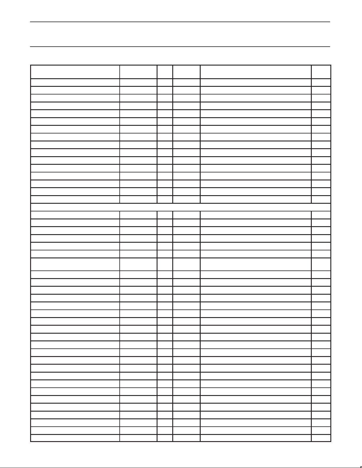
MMR Name
SCC1 Write Register 13 R/W 8 85Ah Upper Byte of Baud rate time constant 00h
SCC1 Write Register 14 R/W 8 85Ch Misc. Control bits xx
SCC1 Write Register 15 R/W 8 85Eh External/Status interrupt control f8h
SCC1 Write Register 16 R/W 8 868h Match Character 2 (WR16) 00h
SCC1 Write Register 17 R/W 8 86Ah Match Character 3 (WR17) 00h
SCC1 Read Register 0 RO 8 860h Tx/Rx buffer and external status —
SCC1 Read Register 1 RO 8 862h Receive condition status/residue code —
Reserved 864h —
SCC1 Read Register 3 RO 8 866h Interrupt Pending Bits —
see WR16 and 17 868–86Ah see WR16 and WR17 above —
SCC1 Read Register 6 RO 8 86Ch SDLC byte count low register —
SCC1 Read Register 7 RO 8 86Eh SDLC byte count high & FIFO status —
SCC1 Read Register 8 RO 8 870h Receive Buffer —
Reserved 872h —
SCC1 Read Register 10 RO 8 874h Loop/clock status —
Reserved 876–87Eh —
SCC2 Write Register 0 R/W 8 880h Command register 00h
SCC2 Write Register 1 R/W 8 882h Tx/Rx Interrupt & data transfer mode xx
SCC2 Write Register 2 R/W 8 884h Extended Features Control xx
SCC2 Write Register 3 R/W 8 886h Receive Parameter and Control 00h
SCC2 Write Register 4 R/W 8 888h Tx/Rx misc. parameters & mode 00h
SCC2 Write Register 5 R/W 8 88Ah Tx. parameter and control 00h
SCC2 Write Register 6 R/W 8 88Ch Sync character or SDLC address field or Match
SCC2 Write Register 7 R/W 8 88Eh Sync character or SDLC flag or Match Character 1 xx
SCC2 Write Register 8 R/W 8 890h Transmit Data Buffer xx
SCC2 Write Register 9 R/W 8 892h Master Interrupt control xx
SCC2 Write Register 10 R/W 8 894h Misc. Tx/Rx control register 00h
SCC2 Write Register 1 1 R/W 8 896h Clock Mode Control xx
SCC2 Write Register 12 R/W 8 898h Lower Byte of Baud rate time constant 00h
SCC2 Write Register 13 R/W 8 89Ah Upper Byte of Baud rate time constant 00h
SCC2 Write Register 14 R/W 8 89Ch Misc. Control bits xx
SCC2 Write Register 15 R/W 8 89Eh External/Status interrupt control f8h
SCC2 Write Register 16 R/W 8 8A8h Match Character 2 (wr16) 00h
SCC2 Write Register 17 R/W 8 8AAh Match Character 3 (wr17) 00h
SCC2 Read Register 0 RO 8 8A0h Tx/Rx buffer and external status —
SCC2 Read Register 1 RO 8 8A2h Receive condition status/residue code —
Reserved 8A4h —
SCC2 Read Register 3 RO 8 8A6h Interrupt Pending Bits —
see WR16 and 17 8A8–8AAh see WR16 and WR17 above —
SCC2 Read Register 6 RO 8 8ACh SDLC byte count low register —
SCC2 Read Register 7 RO 8 8AEh SDLC byte count high & FIFO status —
SCC2 Read Register 8 RO 8 8B0h Receive Buffer —
Reserved 8B2h —
SCC2 Read Register 10 RO 8 8B4h Loop/clock status —
Reserved 8B6–8BEh —
Read/Write or
Read Only
Address
Size
Offset
SCC2 Registers
Description
Character 0
Reset
Value
00h
1999 Mar 29
12
Page 13
Philips Semiconductors Preliminary specification
XA-SCCCMOS 16-bit communications microcontroller
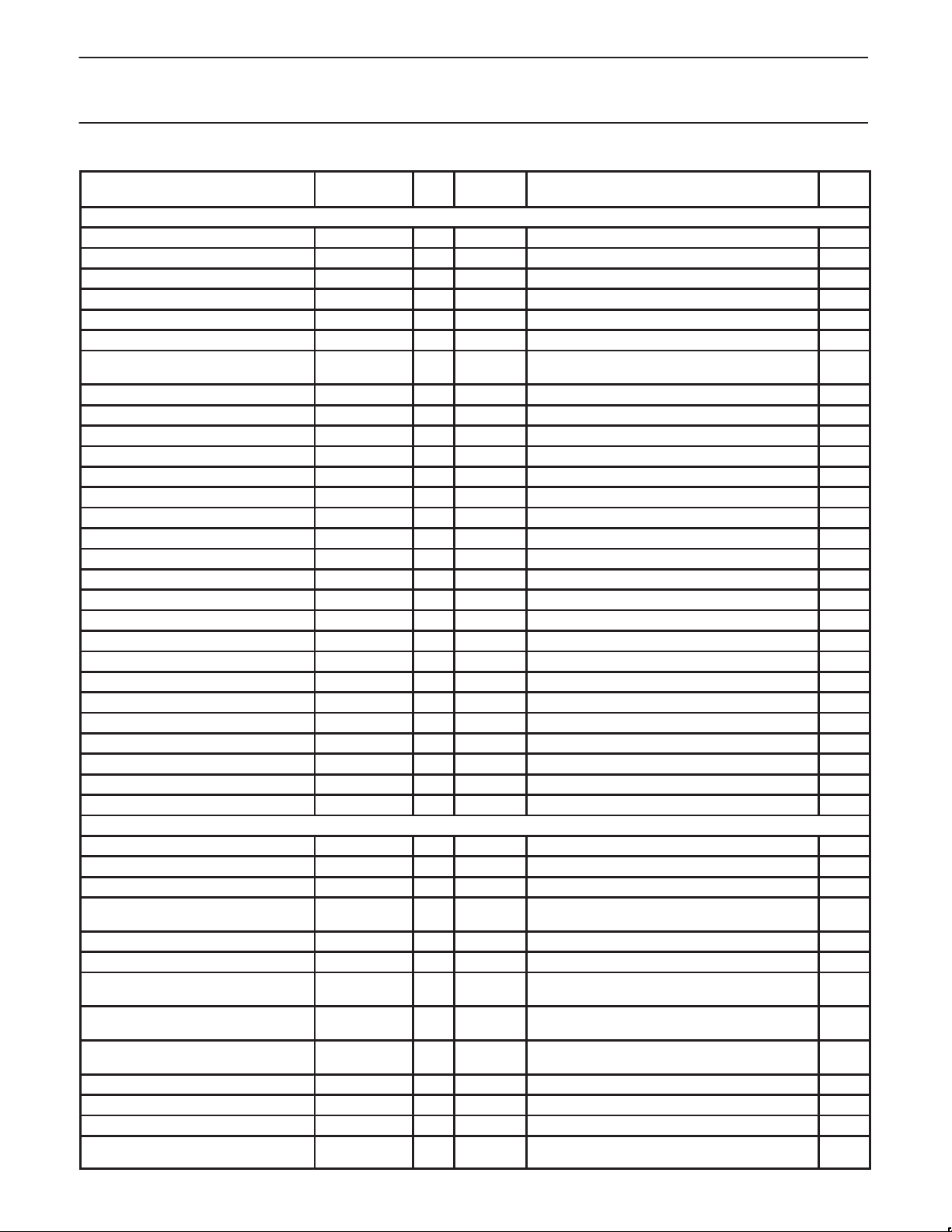
MMR Name
SCC3 Write Register 0 R/W 8 8C0h Command register 00h
SCC3 Write Register 1 R/W 8 8C2h Tx/Rx Interrupt & data transfer mode xx
SCC3 Write Register 2 R/W 8 8C4h Extended Features Control xx
SCC3 Write Register 3 R/W 8 8C6h Receive Parameter and Control 00h
SCC3 Write Register 4 R/W 8 8C8h Tx/Rx misc. parameters & mode 00h
SCC3 Write Register 5 R/W 8 8CAh Tx. parameter and control 00h
SCC3 Write Register 6 R/W 8 8CCh Sync character or SDLC address field or Match
SCC3 Write Register 7 R/W 8 8CEh Sync character or SDLC flag or Match Character 1 xx
SCC3 Write Register 8 R/W 8 8D0h Transmit Data Buffer xx
SCC3 Write Register 9 R/W 8 8D2h Master Interrupt control xx
SCC3 Write Register 10 R/W 8 8D4h Misc. Tx/Rx control register 00h
SCC3 Write Register 1 1 R/W 8 8D6h Clock Mode Control xx
SCC3 Write Register 12 R/W 8 8D8h Lower Byte of Baud rate time constant 00h
SCC3 Write Register 13 R/W 8 8DAh Upper Byte of Baud rate time constant 00h
SCC3 Write Register 14 R/W 8 8DCh Misc. Control bits xx
SCC3 Write Register 15 R/W 8 8DEh External/Status interrupt control f8h
SCC3 Write Register 16 R/W 8 8E8h Match Character 2 (wr16) 00h
SCC3 Write Register 17 R/W 8 8EAh Match Character 3 (wr17) 00h
SCC3 Read Register 0 RO 8 8E0h Tx/Rx buffer and external status —
SCC3 Read Register 1 RO 8 8E2h Receive condition status/residue code —
Reserved 8E4h —
SCC3 Read Register 3 RO 8 8E6h Interrupt Pending Register —
SCC3 Read Register 6 RO 8 8ECh SDLC byte count low register —
SCC3 Read Register 7 RO 8 8EEh SDLC byte count high & FIFO status —
SCC3 Read Register 8 RO 8 8F0h Receive Buffer —
Reserved 8F2h —
SCC3 Read Register 10 RO 8 8F4h Loop/clock status —
Reserved 8F6–8FEh —
DMA Control Register Ch.0 Rx R/W 8 100h Control Register 00h
FIFO Control & Status Reg Ch.0 Rx R/W 8 101h Control & Status Register 00h
Segment Register Ch.0 Rx R/W 8 102h Points to 64K data segment 00h
Buffer Base Register Ch.0 Rx R/W 8 104h Wrap Reload Value for A15 –A8, A7–A0 reloaded
Buffer Bound Register Ch.0 Rx R/W 16 106h Upper Bound (plus 1) on A15–A0 0000h
Address Pointer Reg Ch.0 Rx R/W 16 108h Current Address pointer A15–A0 0000h
Byte Count Register Ch.0 Rx R/W 16 10Ah Corresponds to A15–A0 Byte Count, generates
Data FIFO Register Ch.0 Lo Rx R/W 16 10Ch 10Ch = Byte 0 = older,
Data FIFO Register Ch.0 Hi Rx R/W 16 10Eh 10Eh = Byte 2 = older,
DMA Control Register Ch.1 Rx R/W 8 110h Control Register 00h
FIFO Control & Status Register Ch.1 Rx R/W 8 111h Control & Status Register 00h
Segment Register Ch. 1 Rx R/W 8 112h Points to 64K data segment 00h
Buffer Base Register Ch. 1 Rx R/W 8 114h Wrap Reload Value for A15 –A8, A7–A0 reloaded
Read/Write or
Read Only
Address
Size
Rx DMA Registers
Offset
SCC3 Registers
Description
Character 0
to zero by hardware
interrupt if enabled and byte count exceeded.
10Dh = Byte 1 = younger
10Fh = Byte 3 = younger
to zero by hardware
Reset
Value
00h
00h
0000h
00h
00h
00h
00h
00h
1999 Mar 29
13
Page 14
Philips Semiconductors Preliminary specification
XA-SCCCMOS 16-bit communications microcontroller
MMR Name
Buffer Bound Register Ch.1 Rx R/W 16 116h Upper Bound (plus 1) on A15–A0 0000h
Address Pointer Reg Ch.1 Rx R/W 16 118h Current Address pointer A15–A0 0000h
Byte Count Register Ch.1 Rx R/W 16 11Ah Corresponds to A15–A0 Byte Count, generates
Data FIFO Register Ch.1 Lo Rx R/W 16 11Ch 11Ch = Byte 0 = older,
Data FIFO Register Ch.1 Hi Rx R/W 16 11Eh 11Eh = Byte 2 = older,
DMA Control Register Ch.2 Rx R/W 8 120h Control Register 00h
FIFO Control & Status Register Ch.2 Rx R/W 8 121h Control & Status Register 00h
Segment Register Ch. 2 Rx R/W 8 122h Points to 64K data segment 00h
Buffer Base Register Ch. 2 Rx R/W 8 124h Wrap Reload Value for A15 –A8, A7–A0 reloaded
Buffer Bound Register Ch.2 Rx R/W 16 126h Upper Bound (plus 1) on A15–A0 0000h
Address Pointer Reg Ch.2 Rx R/W 16 128h Current Address pointer A15–A0 0000h
Byte Count Register Ch.2 Rx R/W 16 12Ah Corresponds to A15–A0 Byte Count, generates
Data FIFO Register Ch.2 Lo Rx R/W 16 12Ch 12Ch = Byte 0 = older,
Data FIFO Register Ch.2 Hi Rx R/W 16 12Eh 12Eh = Byte 2 = older,
DMA Control Register Ch.3 Rx R/W 8 130h Control Register 00h
FIFO Control & Status Register Ch.3 Rx R/W 8 131h Control & Status Register 00h
Segment Register Ch. 3 Rx R/W 8 132h Points to 64K data segment 00h
Buffer Base Register Ch. 3 Rx R/W 8 134h Wrap Reload Value for A15 –A8, A7–A0 reloaded
Buffer Bound Register Ch.3 Rx R/W 16 136h Upper Bound (plus 1) on A15–A0 0000h
Address Pointer Reg Ch.3 Rx R/W 16 138h Current Address pointer A15–A0 0000h
Byte Count Register Ch.3 Rx R/W 16 13Ah Corresponds to A15–A0 Byte Count, generates
Data FIFO Register Ch.3 Lo Rx R/W 16 13Ch 13Ch = Byte 0 = older,
Data FIFO Register Ch.3 Hi Rx R/W 16 13Eh 13Eh = Byte 2 = older,
DMA Control Register Ch.0 Tx R/W 8 140h Control Register 00h
FIFO Control & Status Register Ch.0 Tx R/W 8 141h Control & Status Register 00h
Segment Register Ch. 0 Tx R/W 8 142h Points to 64K data segment 00h
Buffer Base Register Ch. 0 Tx R/W 8 144h Wrap Reload Value for A15 –A8, A7–A0 reloaded
Buffer Bound Register Ch.0 Tx R/W 16 146h Upper Bound (plus 1) on A15–A0 0000h
Address Pointer Reg Ch.0 Tx R/W 16 148h Current Address pointer A15–A0 0000h
Byte Count Register Ch.0 Tx R/W 16 14Ah Corresponds to A15–A0 Byte Count, generates
Data FIFO Register Ch.0 Tx R/W 16 14Ch 14C = Byte0 = older
Data FIFO Register Ch.0 Tx R/W 16 14Eh 14E = Byte2 = older
DMA Control Register Ch.1 Tx R/W 8 150h Control Register 00h
FIFO Control & Status Register Ch.1 Tx R/W 8 151h Control & Status Register 00h
Segment Register Ch.1 Tx R/W 8 152h Points to 64K data segment 00h
Read/Write or
Read Only
Address
Size
Tx DMA Registers
Offset
Description
interrupt if enabled and byte count exceeded.
11Dh = Byte 1 = younger
11Fh = Byte 3 = younger
to zero by hardware
interrupt if enabled and byte count exceeded.
12Dh = Byte 1 = younger
12Fh = Byte 3 = younger
to zero by hardware
interrupt if enabled and byte count exceeded.
13Dh = Byte 1 = younger
13Fh = Byte 3 = younger
to zero by hardware
interrupt if enabled and byte count exceeded.
14D = Byte 1 = younger
14F = Byte3 = younger
Reset
Value
0000h
00h
00h
00h
00h
00h
0000h
00h
00h
00h
00h
00h
0000h
00h
00h
00h
00h
00h
0000h
0000h
0000h
1999 Mar 29
14
Page 15
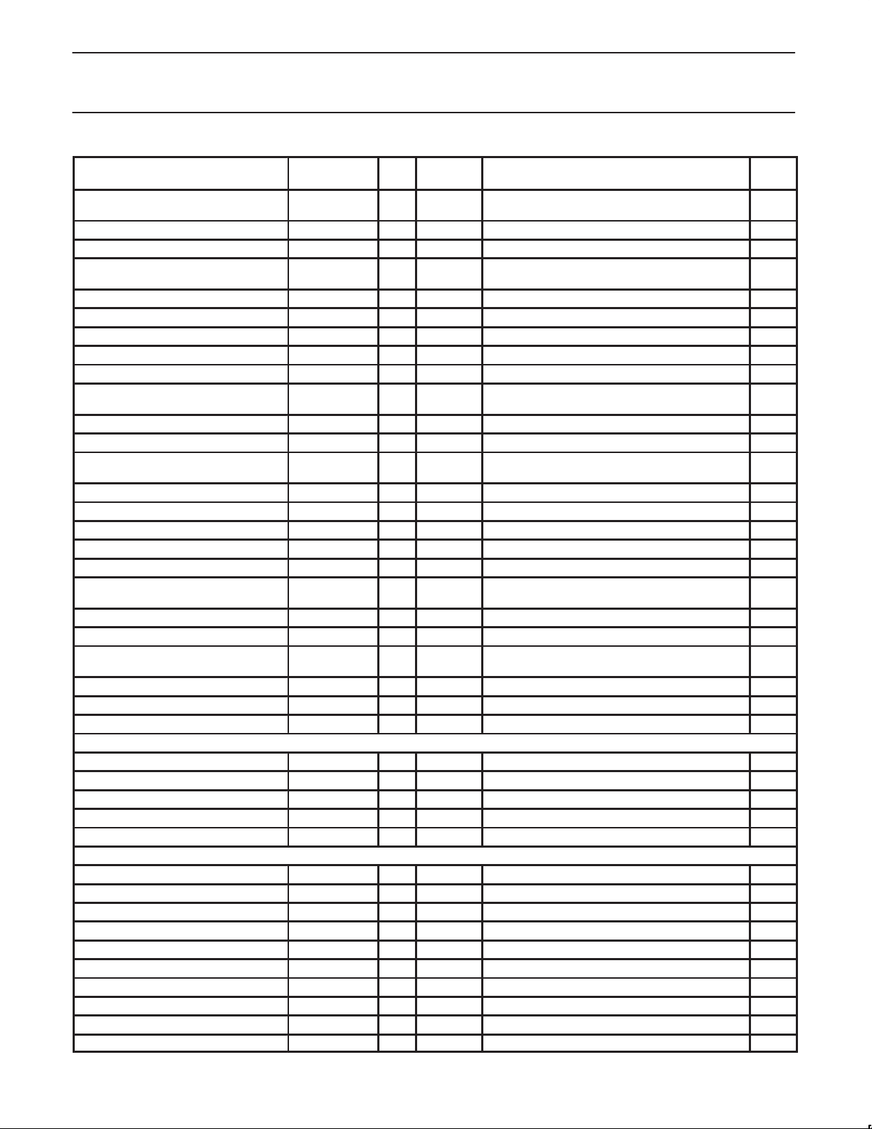
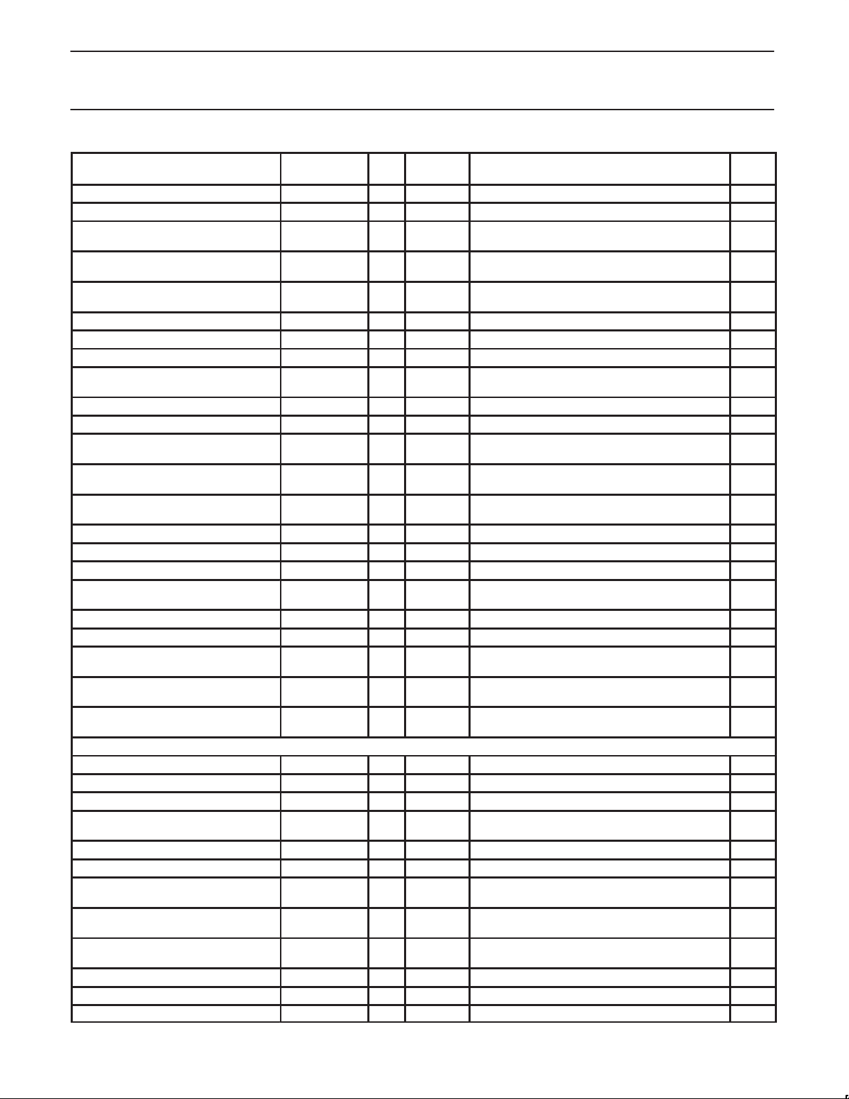
Philips Semiconductors Preliminary specification
XA-SCCCMOS 16-bit communications microcontroller
MMR Name
Buffer Base Register Ch.1 Tx R/W 8 154h Wrap Reload V alue for A15–A8, A7–A0 reloaded
Buffer Bound Register Ch.1 Tx R/W 16 156h Upper Bound (plus 1) on A15–A0 0000h
Address Pointer Reg Ch.1 Tx R/W 16 158h Current Address pointer A15–A0 0000h
Byte Count Register Ch.1 Tx R/W 16 15Ah Corresponds to A15–A0 Byte Count, generates
Data FIFO Register Ch.1 Lo Tx R/W 16 15Ch Byte0 & 1 0000h
Data FIFO Register Ch.1 Hi Tx R/W 16 15Eh Byte2 & 3 0000h
DMA Control Register Ch.2 Tx R/W 8 160h Control Register 00h
FIFO Control & Status Register Ch.2 Tx R/W 8 161h Control & Status Register 00h
Segment Register Ch.2 Tx R/W 8 162h Points to 64K data segment 00h
Buffer Base Register Ch.2 Tx R/W 8 164h Wrap Reload Value for A15 –A8, A7–A0 reloaded
Buffer Bound Register Ch.2 Tx R/W 16 166h Upper Bound (plus 1) on A15–A0 0000h
Address Pointer Reg Ch.2 Tx R/W 16 168h Current Address pointer A15–A0 0000h
Byte Count Register Ch.2 Tx R/W 16 16Ah Corresponds to A15–A0 Byte Count, generates
Data FIFO Register Ch.2 Lo Tx R/W 16 16Ch Byte0 & 1 0000h
Data FIFO Register Ch.2 Hi Tx R/W 16 16Eh Byte2 & 3 0000h
DMA Control Register Ch.3 Tx R/W 8 170h Control Register 00h
FIFO Control & Status Register Ch.3 Tx R/W 8 171h Control & Status Register 00h
Segment Register Ch. 3 Tx R/W 8 172h Points to 64K data segment 00h
Buffer Base Register Ch. 3 Tx R/W 8 174h Wrap Reload Value for A15 –A8
Buffer Bound Register Ch.3 Tx R/W 16 176h Upper Bound (plus 1) on A15–A0 0000h
Address Pointer Reg Ch.3 Tx R/W 16 178h Current Address pointer A15–A0 0000h
Byte Count Register Ch.3 Tx R/W 16 17Ah Corresponds to A15–A0 Byte Count, generates
Data FIFO Register Ch.3Lo Tx R/W 16 17Ch Byte0 & 1 0000h
Data FIFO Register Ch.3 Hi Tx R/W 16 17Eh Byte2 & 3 0000h
Rx Character Time Out Register Ch.0 R/W 8 200h 0 value disables counter interrupt. 00h
Rx Character Time Out Register Ch.1 R/W 8 202h Same as above, for Rx1 00h
Rx Character Time Out Register Ch.2 R/W 8 204h Same as above, for Rx2 00h
Rx Character Time Out Register Ch.3 R/W 8 206h Same as above, for Rx3 00h
Global DMA Interrupt Register R/W 16 210h DMA Interrupt Flags 0000h
VACS R/W 8 240h V.54 2047 Unit A Control & Status 00h
VACFG R/W 8 241h V.54 2047 Unit A Configuration —
VATCL R/W 8 242h V.54 2047 Unit A Threshold Cntr Lo —
VATCH R/W 8 243h V.54 2047 Unit A Threshold Cntr Hi —
VAEC R/W 8 244h V.54 2047 Unit A Error Counter —
VBCS R/W 8 248h V.54 2047 Unit B Control & Status 00h
VBCFG R/W 8 249h V.54 2047 Unit B Configuration —
VBTCL R/W 8 24Ah V.54 2047 Unit B Threshold Cntr Lo —
VBTCH R/W 8 24Bh V.54 2047 Unit B Threshold Cntr Hi —
VBEC R/W 8 24Ch V.54 2047 Unit B Error Counter —
Read/Write or
Read Only
R/W 180–1FEh RESERVED for future DMA —
Miscellaneous DMA Registers
V .54/2047 Registers
Size
Address
Offset
Description
to zero by hardware
interrupt if enabled and byte count exceeded.
to zero by hardware
interrupt if enabled and byte count exceeded.
A7–A0 reloaded to zero by hardware
interrupt if enabled and byte count exceeded.
Reset
Value
00h
0000h
00h
0000h
00h
0000h
1999 Mar 29
15
Page 16
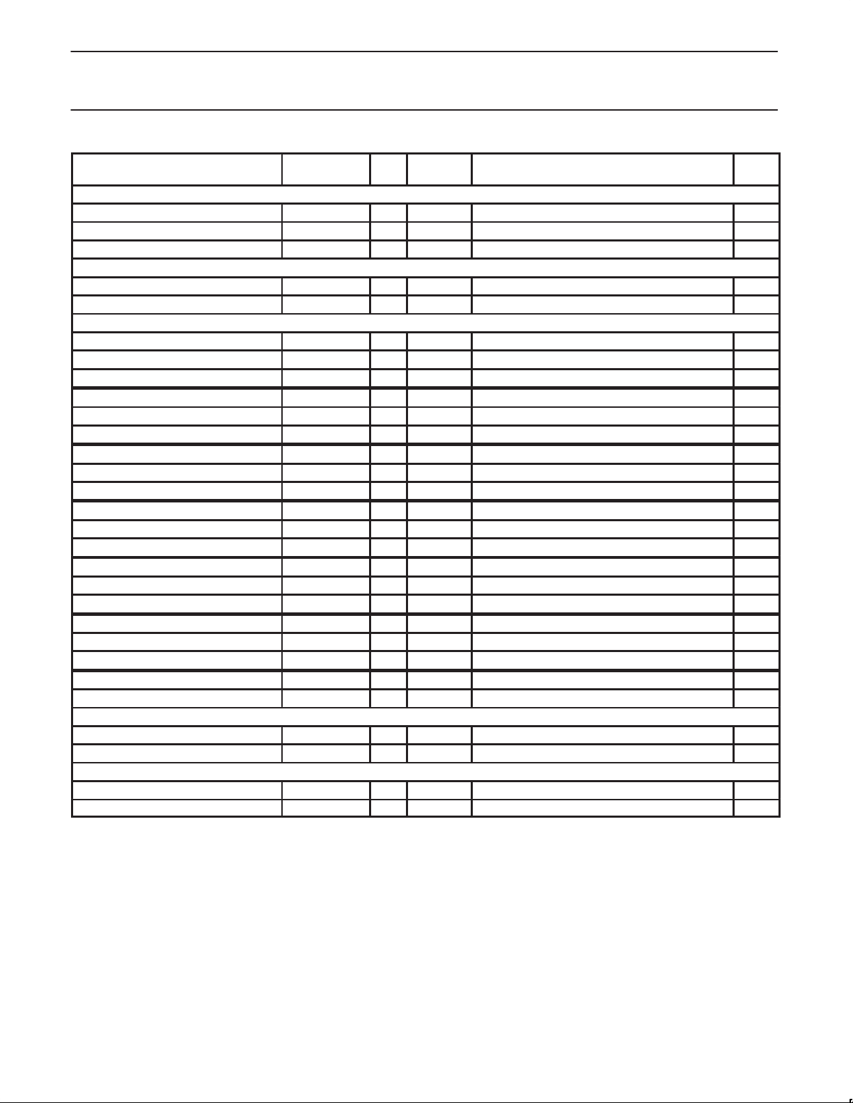
Philips Semiconductors Preliminary specification
XA-SCCCMOS 16-bit communications microcontroller
MMR Name
SCPCFG R/W 8 260h SCP Configuration 8xh
SCPD R/W 8 262h SCP Data Byte xx
SCPCS R/W 8 263h SCP Control & Status 00h
BDAEE R/W 8 270h Autobaud Echo Enable 00h ..
BDCS R/W 8 272h Autobaud Control & Status 00h ..
B0CFG R/W 8 280h MIF Bank 0 Config —
B0AM R/W 8 281h MIF Bank 0 Base Address 00h..
B0TMG R/W 8 282h MIF Bank 0 Timing Params —
B1CFG R/W 8 284h MIF Bank 1 Config 0xh
B1AM R/W 8 285h MIF Bank 1 Base Address xxh
B1TMG R/W 8 286h MIF Bank 1 Timing Params xxh
B2CFG R/W 8 288h MIF Bank 2 Config 0xh
B2AM R/W 8 289h MIF Bank 2 Base Address xx
B2TMG R/W 8 28Ah MIF Bank 2 Timing Params xx
B3CFG R/W 8 28Ch MIF Bank 3 Config 0xh
B3AM R/W 8 28Dh MIF Bank 3 Base Address xx
B3TMG R/W 8 28Eh MIF Bank 3 Timing Params xx
B4CFG R/W 8 290h MIF Bank 4 Config 0xh
B4AM R/W 8 291h MIF Bank 4 Base Address xx
B4TMG R/W 8 292h MIF Bank 4 Timing Params xx
B5CFG R/W 8 294h MIF Bank 5 Config 0xh
B5AM R/W 8 295h MIF Bank 5 Base Address xx
B5TMG R/W 8 296h MIF Bank 5 Timing Params xx
MBCL R/W 8 2BEh MIF Memory Bank Configuration Lock Register 3Fh
RFSH R/W 8 2BFh MIF Refresh Control 00h
MSI Control Register R/W 16 2C0h IDL Mode Control Register 0000h
DataMask Register R/W 16 2C2h IDL Mask Register 0000h
Hi-Pri Soft Ints & Pin Mux Control Reg. R/W 16 2D0h Control bits for Hi-Priority Soft Ints, and Pin Mux 0000h
XInt2 R/W 8 2D2h External Interrupt 2 Control 00h
Read/Write or
Read Only
SCP Interface Registers
Autobaud Registers
Memory Interface (MIF) Registers
IDL Interface Registers
Miscellaneous Registers
Size
Address
Offset
Description
Reset
Value
1999 Mar 29
16
Page 17
Philips Semiconductors Preliminary specification
XA-SCCCMOS 16-bit communications microcontroller
FUNCTIONAL DESCRIPTION
The XA-SCC functions are described in the following sections.
Because all blocks are thoroughly documented in either the IC25 XA
Data Handbook, or the XA-SCC User Manual, only brief descriptions
are given in this datasheet, in conjunction with references to the
appropriate document.
XA CPU
The CPU is a 30MHz implementation of the standard XA CPU core.
See the XA Data Handbook (IC25) for details. The CPU core is
identical to the G3 core. See caveat in next paragraph about the Bus
Interface Unit.
Bus Interface Unit (BIU)
This is the internal Bus, not the bus at the pins. This internal bus
connects the CPU to the MIF (Memory and DRAM Controller.)
WARNING: Immediately after reset, always write BTRH = 51h,
followed by BTRL = 40h, in that order. Once written, do not change
the values in these registers. Follow these two writes with five
NOPS. Never write to the BCR register, it comes out of reset
initialized to 07h, which is the only value that will work.
Timers 0 and 1
Timers 0 and 1 are the standard XA-G3 timer 0 and 1. Each has an
associated I/O pin and interrupt. See the XA-G3 data sheet in the
IC25 XA Data Handbook for details. Many XA derivatives include a
standard XA Timer 2, and standard UARTs. These blocks have been
removed in order to provide other functions on the XA-SCC. There
is no Timer 2, and the UARTs have been replaced with full function
SCCs.
ResetOut
The P3.2_Timer0_ResetOut pin provides an external indication (if
the ResetOut
active low output when an internal reset occurs (internal reset is
Reset instruction or Watchdog time out.) If the ResetOut
enabled, the ResetOut
occurs or the Reset instruction is executed. This signal may be used
to inform other devices in the system that the XA-SCC has been
internally reset. The ResetIn
ResetOut
256 system clocks.
WARNING: At power on time, from the time that power coming up is
valid, the P3.2_Timer0_ResetOut
period from zero nanoseconds up to 258 system clocks. This is true
independently of whether ResetIn is active or not.
function is enabled in the RSRSRC register) via an
function is
pin will be driven low when a Watchdog reset
signal does NOT get passed on to
. When activated, the duration of the ResetOut pulse is
pin may be driven low for any
Reset Source Register
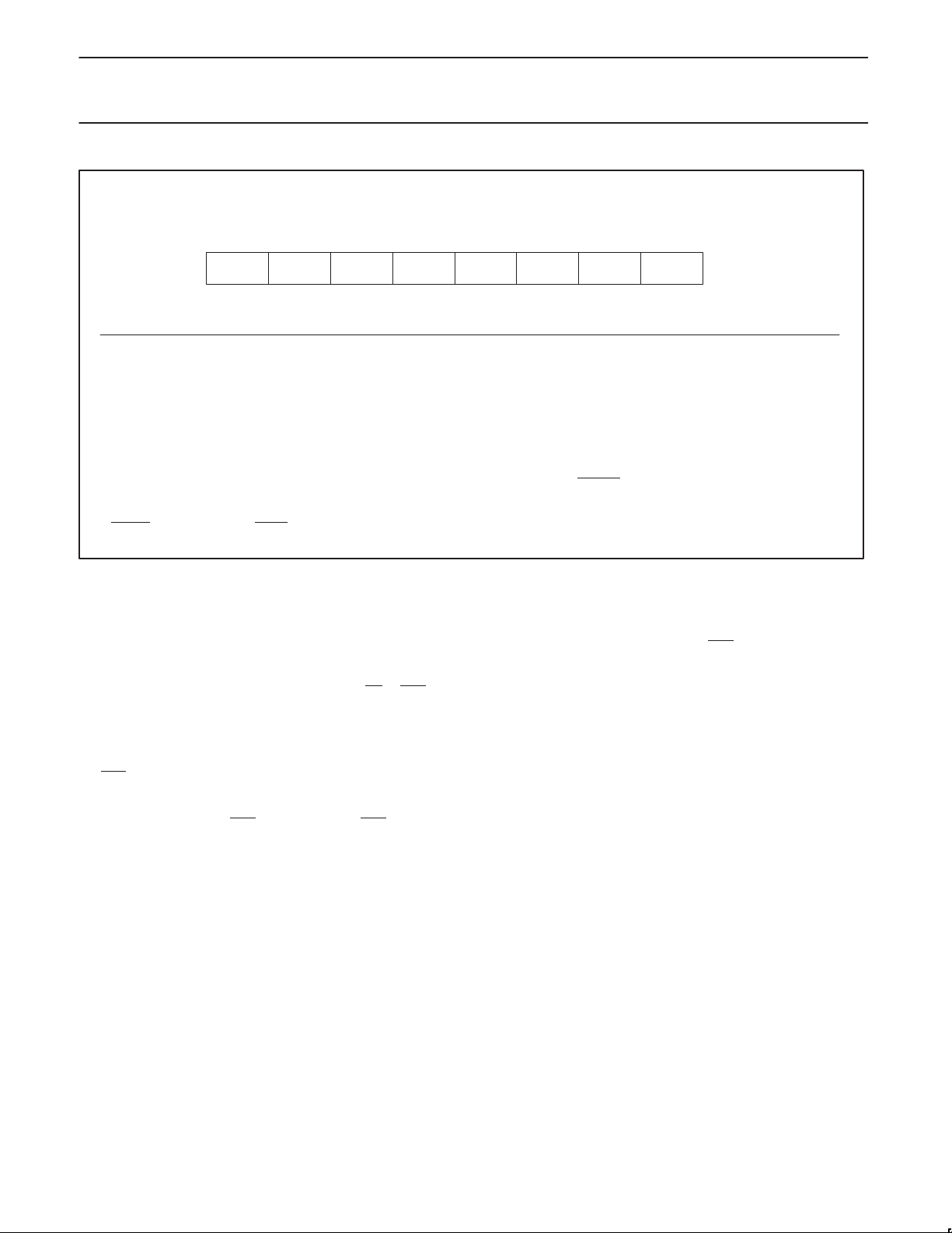
The reset source identification register (RSTSRC) indicates the
cause of the most recent XA reset. The cause may have been an
externally applied reset signal, execution of the RESET instruction,
or a Watchdog reset. Figure 2 shows the fields in the RSTSRC
register. If the ResetOut
then all resets will be external resets, and will thus appear as
external resets in the reset source register. RSTSRC[7] enables the
ResetOut
Manual for details; RSTSRC[7] differs in function from most other
XA derivatives.
function; 1 = Enabled, 0 = Disabled. See XA-SCC User
function is tied back into the ResetIn pin,
Watchdog Timer
This timer is a standard XA-G3 Watchdog Timer. See the G3
datasheet in IC25. Also, if you intend to use the Watchdog Timer to
assert the ResetOut
The Watchdog Timer is enabled at reset, and must be periodically
fed to prevent timeout. If the watchdog times out, it will generate an
internal reset; and if ResetOut
generate a ResetOut
pin, see ResetOut in the XA-SCC User Manual.
is enabled the internal reset will
pulse (active low pulse on ResetOut pin.)
Reset
On the XA-SCC there are two pins associated with reset. The
ResetIn
pin provides an external reset into the XA-SCC. The port
pin P3.2_Timer0_ResetOut
Because ResetOut does not reflect ResetIn, the ResetOut pin can
be tied directly back into the ResetIn
logic. This configuration will make all resets (internal or external)
appear to the XA as external resets. See the XA-SCC User Manual
for a full discussion of the reset functions.
output can be configured as ResetOut.
pin without other PC board
ResetIn
The ResetIn function is the standard XA-G3 ResetIn function. The
ResetIn
signal does NOT get passed on to ResetOut. See the
XA-SCC User Manual for details on reset.
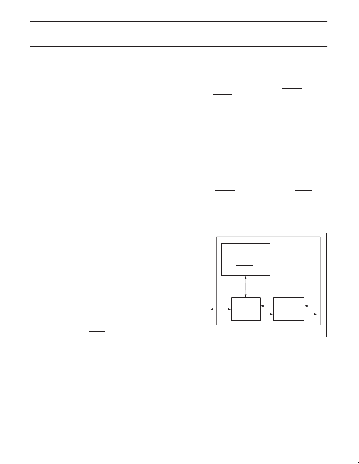
XA CPU
BIU
INTERNAL CPU BUS
EXTERNAL
MEMORY
and I/O BUS
Figure 2. XA CPU Core BIU (Bus Interface Unit)
MIF and
DRAM
CONTROLLER
DMA
CHANNELS
x8
SU01123
1999 Mar 29
17
Page 18
Philips Semiconductors Preliminary specification
XA-SCCCMOS 16-bit communications microcontroller
RSTRC
Bit Symbol Function
RSTSRC.7 ROEN ResetOut function enable bit – see XA–SCC User Manual for details
RSTSRC.6 – Reserved for future use. Should not be set to 1 by user programs.
RSTSRC.5 – Reserved for future use. Should not be set to 1 by user programs.
RSTSRC.4 – Reserved for future use. Should not be set to 1 by user programs.
RSTSRC.3 – Reserved for future use. Should not be set to 1 by user programs.
RSTSRC.2 R_WD Indicates that the last reset was caused by a watchdog timer overflow (see WARNING.)
RSTSRC.1 R_CMD Indicates that the last reset was caused by execution of the RESET instruction (see WARNING.)
RSTSRC.0 R_EXT Indicates that the last reset was caused by the external ResetIn
WARNING:
If ResetOut
DRAM Controller and Memory/IO Bus Interface
(MIF)
In the memory or system bus interface terminology, generic bus
cycles are synonymous with SRAM bus cycles, because these
cycles are designed to service SRAMs, Flash, EEPROM, peripheral
chips, etc. Chip select output pins function as either CS
depending on whether the memory bank has been programmed as
generic or DRAM.
The XA-SCC has a highly programmable memory bus interface with
a complete onboard DRAM controller. Most DRAMs (up to 8MBytes
per RAS
connected to this interface with zero glue chips. The bus interface
provides 6 mappable chip select outputs, five of which can be
programmed to function as RAS
proper address multiplexing for a wide range of DRAM sizes, and
refresh are all generated onboard. The bus timing for each individual
Reg Type and Address = SFR 463h
Not Bit Addressable
ROEN ————R_WD R_CMD R_EXT
Bit:
function is tied back into ResetIn pin, RSTSRC will always show external reset ONLY, because external reset always takes precedence over internal reset.
pin), SRAMs, Flash, ROMs, and peripheral chips can be
76543210
input.
Figure 3. RSTSRC Reset Source Register
memory bank or peripheral can be programmed to accommodate
slow or fast devices.
Each memory bank and it’s associated RAS
DRAM mode) output, can be programmed to access up to an
or RAS
strobes to DRAM. CAS generation,
8MByte mappable address space in either EDO or FPM DRAM
modes (up to a total of 16MB of DRAM, or 32MB if 16MB of data
space and 16MB code space is elected. WARNING: Future
XA-SCC derivatives may not support separate code and data
spaces.)
Each memory bank and associated chip select programmed for
“generic” (SRAM, Flash, ROM, peripheral chips, etc) is capable of
supporting a 1Mbyte address space (six chip selects can thus
support 6MB of SRAM and other generic devices.)
The Memory Interface can be programmed to support both Intel
style and 68000 bus style SRAMs and peripherals.
Reset Value = see below
LSBMSB
(chip select pin in
SU01124
1999 Mar 29
18
Page 19
Philips Semiconductors Preliminary specification
XA-SCCCMOS 16-bit communications microcontroller
Bus Interface Pins
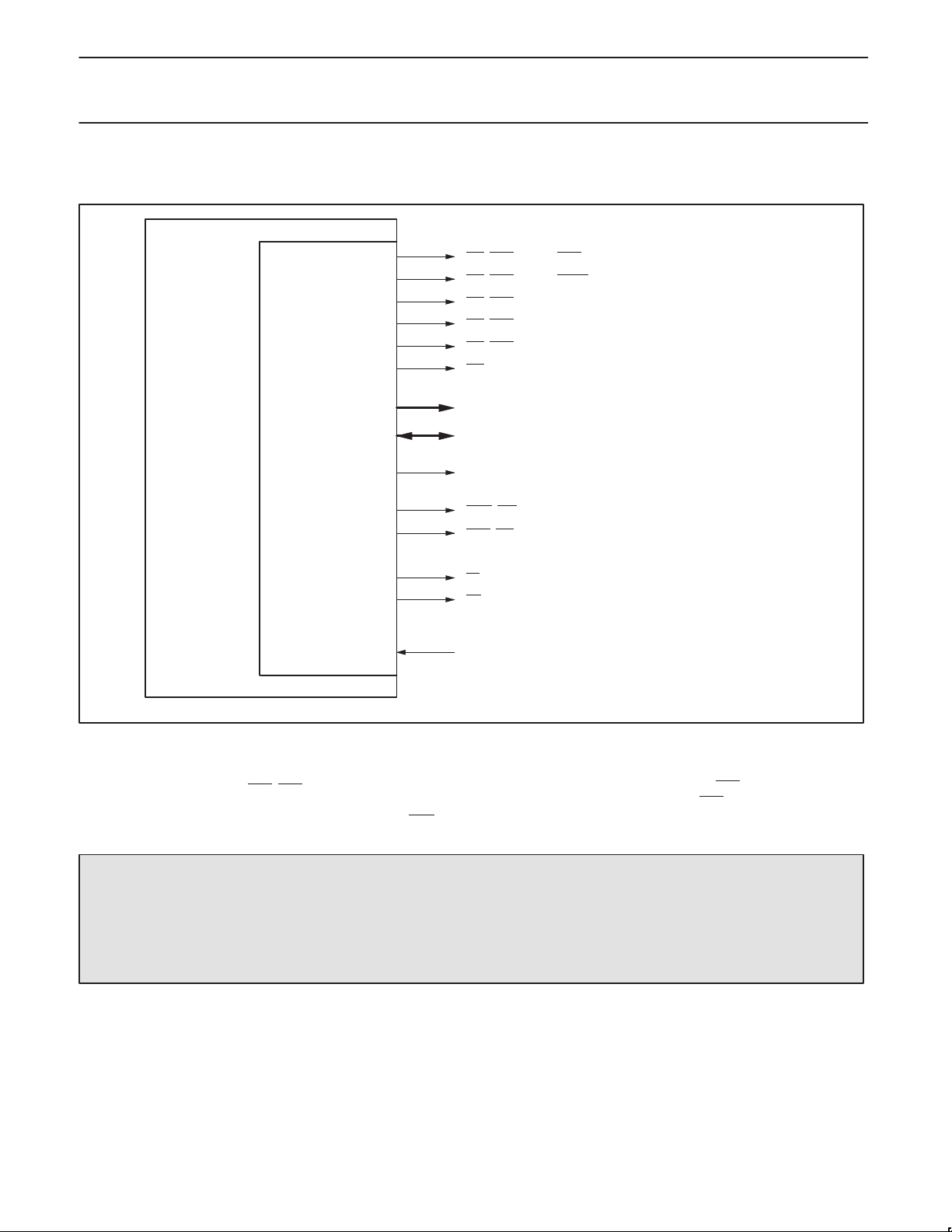
For this discussion, see Figure 4.
XA–SCC
CS5, RAS5, (or P3.1, RTS1)
CS4, RAS4, (or P3.0, RTClk1)
, RAS3
CS3
CS2, RAS2
CS1, RAS1
CS0
A19–A0 (IF DRAM CYCLE, A22–A0 ARE TIME-MULTIPLEXED FOR RAS/CAS)
MIF
(MEMORY CONTROLLER)
D15–D0
ClkOut
CASH, BHE
CASL, BLE
OE
WE
WAIT, SIZE16
SU01125
Figure 4. Memory Bus Interface Signal Pins
Chip Selects and RAS pins
There are six chip select pins (CS5–CS0) mapped to six sets of
bank control registers. The following attributes are individually
programmable for each bank and associated chip select (or RAS
if
detailed bus strobe sequence, DRAM cycle or generic bus cycle,
DRAM size if DRAM, and bus width. Pin CS0
order to service the boot device, thus CS0
is always generic in
cannot be connected to
DRAM.
DRAM): bank on/off, address range, external device access time,
WARNING: On the external bus, ALL XA-SCC reads are 16 bit Reads. If the CPU instruction only specifies 8 bits, then the CPU uses
the appropriate byte, and discards the extra byte. Thus “8 Bit Reads” appear to be identical on the bus. On an 8 bit bus, this will
appear as two consecutive 8 bit reads even though the CPU instruction specified a byte read
Some 8 bit I/O devices (especially FIFOs) cannot operate correctly with 2 bytes being Read for a 1 Byte Read. The most common (and
least expensive) solution is to operate these 8 bit devices on a 16 bit bus, and access them in software on all odd byte (or all even byte)
boundaries. An added benefit of this technique is that byte reads are faster than on an 8 bit bus, because only 1 word is fetched (a single
read) instead of 2 consecutive bytes.
Clock Output
The CLKOUT pin allows easier external bus interfacing in some
situations. This output reflects the XTALIn clock input to the XA
(referred to internally as CClk or System Clock), but is delayed to
match the external bus outputs and strobes. The default is for
1999 Mar 29
CLKOUT to be output enabled at reset, but it may be turned off
(tri-state disabled) by software via the MICFG MMR.
WARNING: The capacitive loading on this output must not
exceed 40pf.
19
Page 20
Philips Semiconductors Preliminary specification
XA-SCCCMOS 16-bit communications microcontroller
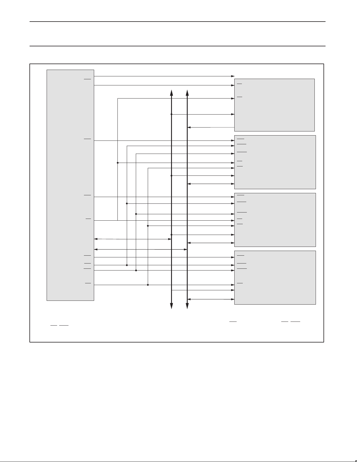
XA–SCC
CS0
CS1
CS2
OE
A19–A0
D15–D0
CS3
BLE
BHE
WE
A17–A9
D15–D0
A17–A8
CS
OE
A16–A0
D7–D0
RAS
CASL
CASH
OE
WE
A8–A0
D15–D0
RAS
CASL
CASH
OE
WE
A9–A0
D15–D0
RAS
CASL
CASH
WE
A15–A1
D15–D0
128K x 8 ROM
256K x 16 DRAM
(HM514260DI)
1M x 16 DRAM
(MT4C1M16C3)
32K x 16 SRAM
NOTE:
During DRAM cycles only, the appropriate CAS Address will be multiplexed onto pins A17–A7 after the assertion or RAS
BLE (CASL). See AC timing diagrams and the XA–SCC User Manual for complete details.
1999 Mar 29
and prior to the assertion of BHE (CASH) and
SU01126
Figure 5. Typical System Bus Configuration
20
Page 21
Philips Semiconductors Preliminary specification
XA-SCCCMOS 16-bit communications microcontroller
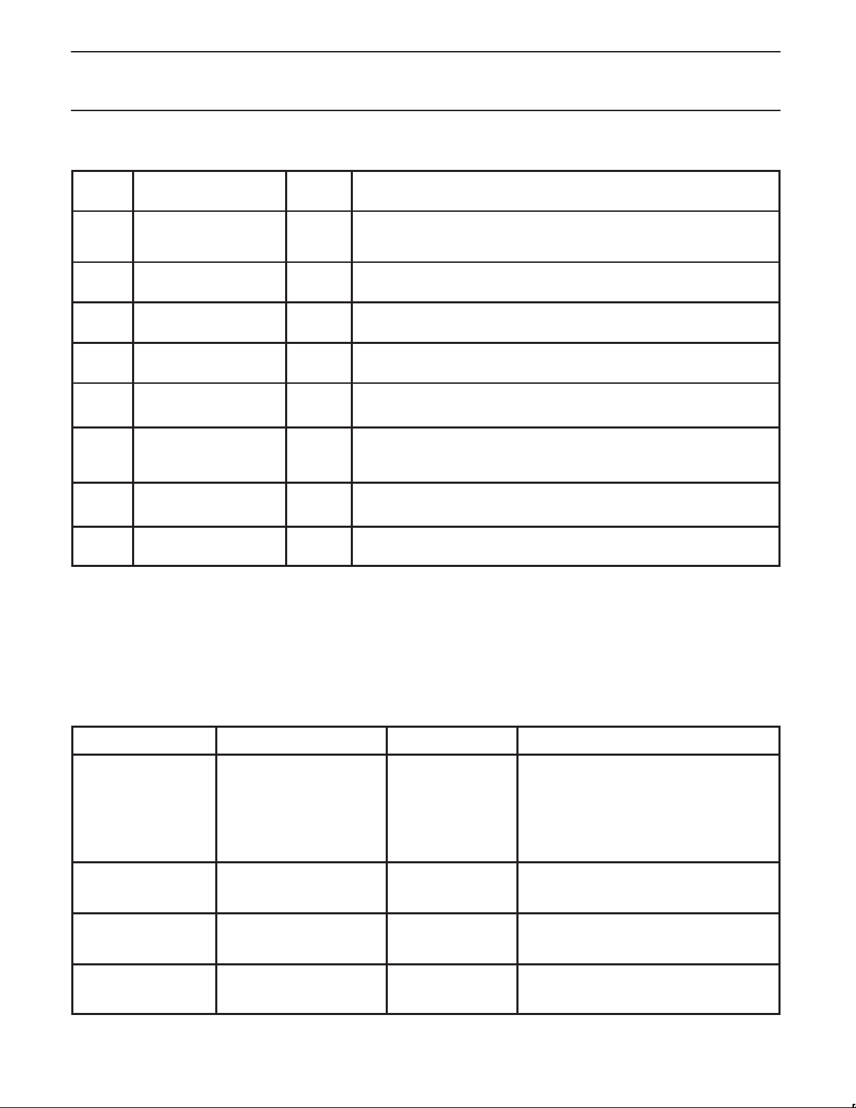
Table 3. Memory Interface Control Registers
Reg
Register Name
Type
Description
MRBH “MMR Base Address”
MRBL “MMR Base Address” Low SFR
MICFG MIF Configuration MMR
MBCL Memory Bank
BiCFG
BiAM
BiTMG
RFSH
High
Configuration Lock
Bank i Configuration MMR
Bank i Base
Address/DRAM Address
Multiplexer Control
Bank i Timing MMR
Refresh Timing MMR
SFR
8 bits
8 bits
8 bits
MMR
8 bits
8 bits
MMR
8 bits
8 bits
8 bits
This SFR is used to relocate the MMRs. It contains address bits a23–a16 of the
base address for the 4 KByte Memory Mapped Register space. See XA-SCC User
Manual for using this SFR to relocate the MMRs.
Contains address bits a15–a12 of the base address for the 4 KByte Memory
Mapped Register space.
Contains the CLKOUT Enable bit.
Contains the bits for locking and unlocking the BiCFG Registers.
Contains the size, type, bus width, and enable bits for Memory Bank i.
Contains the base address bits and DRAM address multiplex control bits for
Memory Bank i.
Contains the timing control bits for Memory Bank i.
Contains the refresh time constant and DRAM Refresh Timer enable bit.
Eight Channel DMA Controller
The XA-SCC has eight DMA channels; one Rx DMA channel
dedicated to each SCC Receive (Rx) channel, and one Tx DMA
channel dedicated to each SCC Transmit (Tx) channel. All DMA
channels are optimized to support memory efficient circular data
buffers in external memory. All DMA channels can also support
traditional linear data buffers.
Transmit DMA Channel Modes
The four Tx channels have four DMA modes specifically designed
for various applications of the attached SCCs. These modes are
summarized in the following table. Full details for all DMA functions
can be found in the DMA chapter of the XA-SCC User Manual.
Table 4. Tx DMA Modes Summary
Mode Byte Count Source Maskable Interrupt Description
Non-SDLC/HDLC
Tx Chaining
SDLC/HDLC
Tx Chaining
Stop on TC Processor loads Byte Count
Periodic Interrupt Processor loads Byte Count
1999 Mar 29
Header in memory On stop DMA channel picks up header from memory at
Header in memory End of packet (not
Register (for each fragment)
Register (only once)
end of fragment)
Byte count completed
(Tx DMA stops)
Each time byte count
completed (Tx DMA
continues)
21
end of transmission. If byte count in header is
greater than zero, then DMA transmits the
number of bytes specified in the byte count. If
byte count equals 0, then a maskable interrupt is
generated. This process repeats until byte count
in data header is zero. See XA-SCC User
manual for details.
Same as above, except DMA header
distinguishes between fragment of packet and
full pack. See XA-SCC User manual for details.
Processor loads byte count into DMA. DMA
sends that number of bytes, generates maskable
interrupt, and stops.
DMA runs until commanded to stop by
processor. Everytime byte counter rolls over, a
new maskable interrupt is generated.
Page 22
Philips Semiconductors Preliminary specification
XA-SCCCMOS 16-bit communications microcontroller
Receive DMA Channel Modes
The Rx DMA channels have four DMA modes specifically designed
for various applications of the attached SCCs. These modes are
Table 5. Rx DMA Modes Summary
Mode Byte Count Source Maskable Interrupt Description
SDLC/HDLC Rx
Chaining
Periodic Interrupt Loaded by processor into DMA,
Asynchronous
Character Time Out
Asynchronous
Character Match
DMA stores byte count in header in
memory with data packet.
used only to determine the number
of bytes between interrupts.
Processor can infer the byte count
from the DMA address pointer.
Byte Count can be calculated by
software from the DMA address
pointer.
Byte Count can be calculated by
software from the DMA address
pointer.
At end of received
packet
When Byte Counter
reaches zero and is
reloaded by DMA
hardware from the byte
count register.
If no character is
received within a
specified time out
period, then interrupt.
When matched
character is stored in
memory.
summarized in the following table. For full details on implementation
and use, see the XA-SCC User Manual.
When a complete or aborted SDLC/HDLC
packet has been received, the packet byte count
and status information are stored in memory with
the packet. A maskable interrupt is generated.
The DMA channel runs until commanded to stop
by the processor. It generates a maskable
interrupt once per n bytes, where n is the
number written once into the byte count register
by the processor, thus an interrupt is generated
once every n received bytes.
Processor specifies time out period between
incoming characters. If no character is received
within that time, interrupt is generated.
There are four match registers, each incoming
character is compared to all four registers. When
a matched character is stored in memory by
DMA, a maskable interrupt is generated.
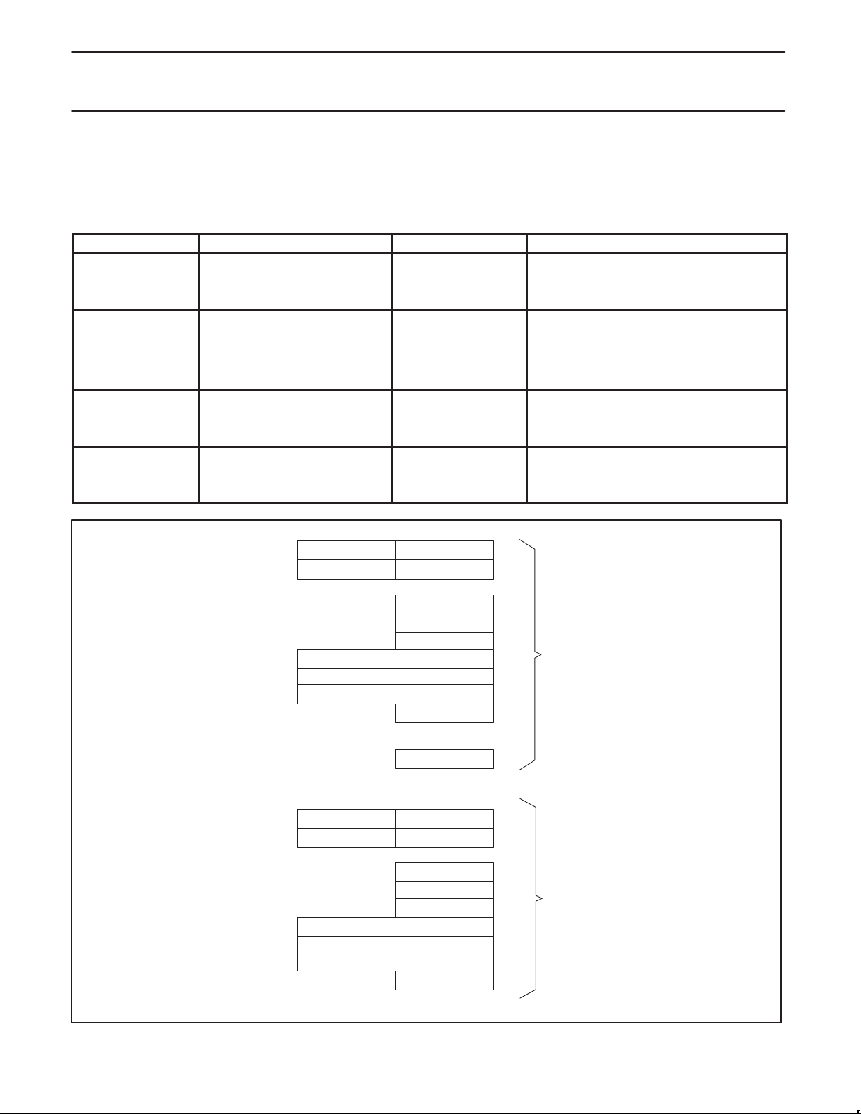
DATA FIFO 3 DATA FIFO 2
DATA FIFO 1 DATA FIFO 0
DMA CONTROL
SEGMENT
BUFFER BASE
BUFFER BOUND
ADDRESS POINTER
BYTE COUNT
DATA FIFO 3 DATA FIFO 2
DATA FIFO 1 DATA FIFO 0
BUFFER BOUND
ADDRESS POINTER
BYTE COUNT
FIFO CONTROL
Rx TIME OUT
DMA CONTROL
SEGMENT
BUFFER BASE
FIFO CONTROL
Rx CHANNEL
Tx CHANNEL
1999 Mar 29
SU01127
Figure 6. Rx and Tx DMA Registers
22
Page 23

Philips Semiconductors Preliminary specification
XA-SCCCMOS 16-bit communications microcontroller
DMA Registers
In addition to the 16-bit Global DMA Interrupt Register (which is
shared by all eight DMA channels), each DMA channel has seven
control registers and a four-byte Data FIFO. The four Rx DMA
channels have one additional register, the Rx Character Time Out
Register. All DMA registers can be read and written in Memory
Mapped Register (MMR) space. These registers are summarized
below.
•Global DMA Interrupt Register (not shown in figure): All DMA
interrupt flags are in this register .
•DMA Control Register: Contains the master mode select and
interrupt enable bits for the channel.
•Segment Register: Holds A23–A16 (the current segment) of the
24-bit data buffer address.
•Buffer Base Register: Holds a pointer (A15–A8) to the lowest byte
in the memory buffer.
•Buffer Bound Register: Points to the first out-of-bounds address
above a circular buffer.
•Address Pointer Register: Points to a single byte or word in the
data buffer in memory. The 24-bit DMA address is formed by
concatenating the contents of the Segment Register [A23–A16]
with the contents of the Address Pointer Register [A15–A0].
•Byte Count Register: Holds the initial number of bytes to be
transferred. In Tx Chaining mode, this register is not used
because the byte count is brought into the byte counter from
buffer headers in memory.
•FIFO Control & Status Register: Holds the queuing order and
full/empty status for the Data FIFO Registers.
•Data FIFO Registers: A four-byte data FIFO buffer internal to the
DMA channel.
•Rx Char Time Out Register (RxCTOR, Rx DMA channels only):
Holds the initial value for an 8-bit character timeout countdown
timer which can generate an interrupt.
Quad Serial Communications Controllers with
Autobaud
•Asynchronous features:
– Asynchronous transfers up to 921.6Kbps
– Can monitor input stream for up to four match characters per
receiver
– 5, 6, 7, or 8 data bits per character.
– 1, 1.5, or 2 Stop bits per character.
– Even or Odd parity generate and check.
– Parity, Rx Overrun, and Framing Error detection.
– Break detection.
– Supports hardware Autobaud detection and response up to
921.6Kbps.
•SDLC/HDLC features:
– Automatic Flag and Abort Character generation and
recognition.
– Automatic CRC generation and checking (can be disabled for
“pass-thru.”)
– Automatic zero-bit insertion and stripping.
– Automatic partial byte residue code generation.
– 14-bit Packet byte count stored in memory with received packet
by DMA.
•Synchronous character oriented protocol features:
– Automatic CRC generation and checking.
– One (Monosync) or two (Bisync) sync characters option.
– External Sync option.
•Transparent mode for bit-streaming applications.
•Data encoding/decoding options:
– FM0 (Biphase Space)
– FM1 (Biphase Mark)
– NRZ
– NRZI
•Programmable Baud Rate Generator, and 7/8 Clock Prescaler
option.
•Auto Echo and Local Loopback modes.
•Supports hardware V.54/2047 generation and checking.
•IDL (2B + D) supported on three SCC channels. Supports both “8
bit” and “10 bit” IDL.
IDL Time Division Multiplexor
SCC0, SCC1, and SCC2 can be internally connected to the on-chip
IDL Interface, a glueless industry standard interface to Layer One
devices such as U-Chips or S/T chips. Thus connected, the three
SCCs can efficiently support the ISDN B1, B2, and D channels,
while the IDL Interface time-multiplexes and demultiplexes the
outgoing and incoming serial data streams.
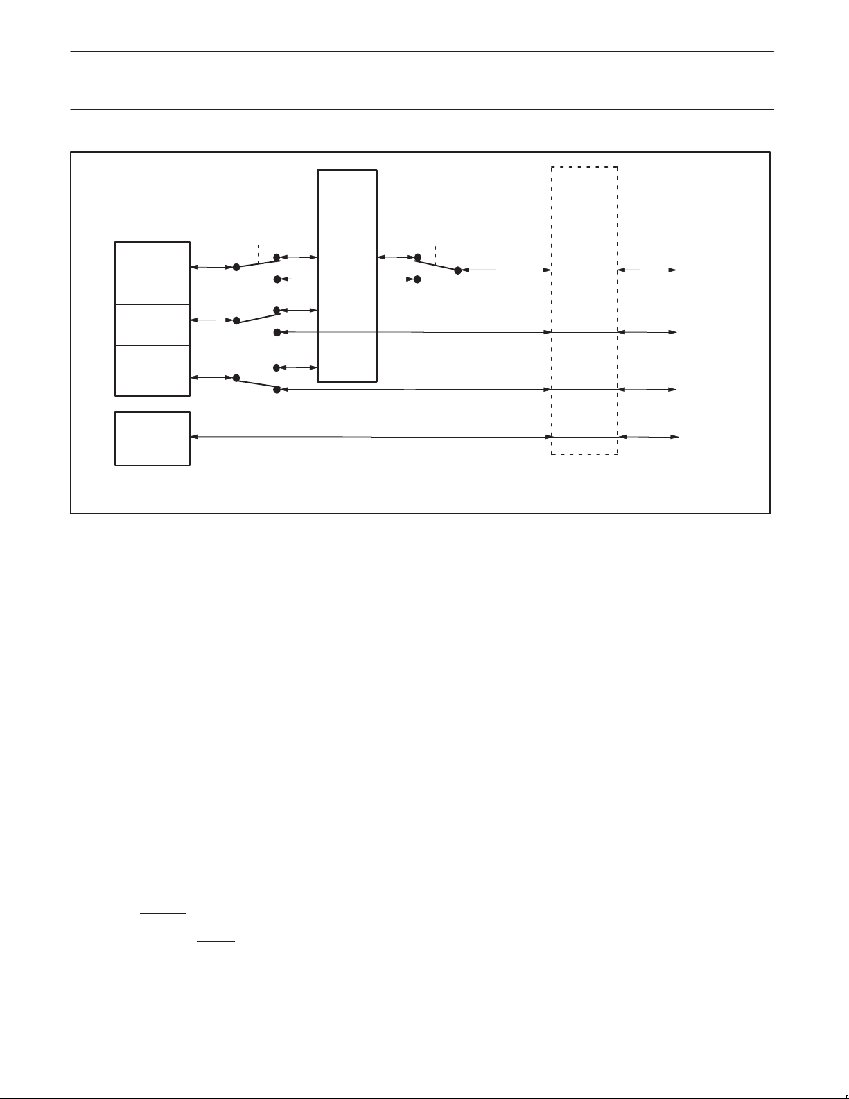
If software enables the IDL interface, then SCC0 is connected to
IDL. Optionally , the software can also connect SCC1 and SCC2 to
the IDL interface. SCC3 cannot be connected to the IDL interface.
See the IDL chapter in the XA-SCC User Manual.
In Figure 7, SCC0 is connected to IDL because IDL has been
enabled by software. Software, in this example has also connected
SCC1 to IDL, and has bypassed IDL for SCC2. SCC3 cannot be
connected to IDL. If there are pins not being used by any of the
SCCs, software can assign alternate functions to those pins; see the
pin steering logic in the “Pins” appendix of the XA-SCC User
Manual. For complete documentation on the IDL interface, see the
IDL chapter in the XA-SCC User Manual.
SCP Serial Interface Controller
The SCP Interface provides a full duplex, industry standard
synchronous serial communication bus, similar to SPI and
Microwire. SCP can be used to transfer control and status
information to other chips, and for accessing serial flash devices.
See the IDL interface chapter in the XA-SCC User Manual.
1999 Mar 29
23
Page 24
Philips Semiconductors Preliminary specification
XA-SCCCMOS 16-bit communications microcontroller
PIN
IDL
FUNCTION
MUX
IDL On
SCC 0
SCC 1
SCC 2
SCC 3
Figure 7. IDL Connection Options
Dual v.54 and 2047 Generators/Checkers
One of the two hardware generator/checkers which support the
V .54/2047 line testing standards can be attached to each SCC.
During V .54/2047 line testing sequences, the V.54/2047 units can be
programmed to generate an interrupt when certain error criteria
have been detected on the transmissions lines. The CPU can
determine the quality of the transmission line by reading the
V .54/2047 units’ status registers.
Autobaud Detectors
Each SCC has it’s own Autobaud detector, capable of baud rate
detection up to 921.6Kbaud. The detectors can be programmed to
automatically echo the industry standard autobaud sequences. They
can be programmed to update the necessary control registers in the
SCCs, and turn on the receiver; which in turn will automatically
initiate DMA into memory of received data. Thus, once the baud rate
is determined, reception begins without intervention from the
processor. When the baud rate is detected, a maskable interrupt is
sent to the processor. See the Autobaud chapter in the XA-SCC
User Manual for details.
I/O PORT OUTPUT CONFIGURA TION
Port input/output configurations are the same as standard XA ports:
open drain, quasi-bidirectional, push-pull, and off (off means tri-state
Hi-Z, and allows the pin to be used as an input. WARNING: At
power on time, from the time that power coming up is valid, the
P3.2_Timer0_ResetOut
pin may be driven low for any period from
zero nanoseconds up to 258 system clocks. This is true
independently of whether ResetIn
is active or not.
POWER REDUCTION MODES
The XA-SCC supports Idle and Power Down modes of power
reduction. The idle mode leaves most peripherals running in order to
allow them to activate the processor when an interrupt is generated.
IDL On
IF IDL ON
IDL PINS,
ELSE
SCC0 PINS
SCC1 PINS
OR GPIO
SCC2 PINS
OR GPIO
SCC3 PINS
OR GPIO
The Pin Function Mux is used to enable
alternate functions on unused pins.
SU01128
The power down mode stops the oscillator in order to absolutely
minimize power. The processor can be made to exit power down
mode via a reset or one of the external interrupt inputs (INT0 or
INT1). This will occur if the interrupt is enabled and its priority is
higher than that defined by IM3 through IM0. In power down mode,
the power supply voltage may be reduced to the RAM keep-alive
voltage V
. This retains the RAM, register, and SFR contents at
RAM
the point where power down mode was entered. WARNING: V
must be raised to within the operating range before power down
mode is exited.
INTERRUPTS
In the XA architecture, all exceptions, including Reset, are handled
in the same general exception structure. The highest priority
exception is of course Reset, and it is non-maskable. All exceptions
are vectored through the Exception Vector Table in low memory.
Coming out of Reset, these vectors must be stored in non-volatile
memory based at location 000000. Later in the boot sequence,
DRAM or SRAM can be mapped into this address space if desired.
There is a feature in the XA-SCC Memory Controller called “Bank
Swap” that supports replacing the ROM vector table and other low
memory with RAM. See the XA-SCC User Manual for details.
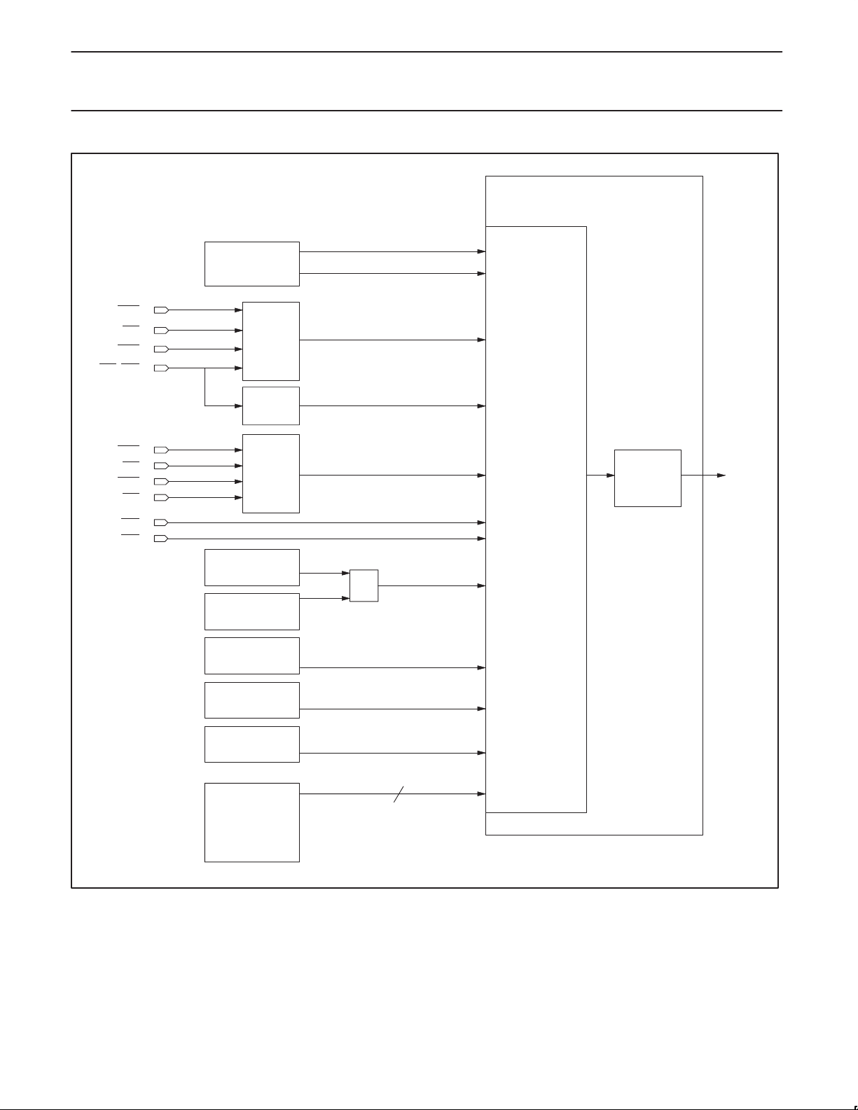
The XA-SCC has a standard XA CPU Interrupt Controller,
implemented with 15 Maskable Event Interrupts. Event Interrupts
are defined as maskable interrupts usually generated by hardware
events. However, in the XA-SCC, 4 of the 15 Event Interrupts are
generated by software writing directly to the interrupt flag bit. These
4 interrupts are referred to as High Priority Software Interrupts.
See the IC25 XA Data Handbook for a full explanation of the
exception structure, including event interrupts, of the XA CPU.
Because the High Priority Software Interrupts are specific to the
XA-SCC, they are explained in the XA-SCC User Manual.
DD
1999 Mar 29
24
Page 25
Philips Semiconductors Preliminary specification
XA-SCCCMOS 16-bit communications microcontroller
XA CORE
INTERRUPT CONTROLLER
DMAH
CTS0
CD0
CTS1
CD1_INT2
DMA
INTERRUPTS
SCC0/
SCC1
INT2
DMAL
INTERRUPT
ENABLE/
DISABLE BITS
CTS2
CD2
CTS3
CD3
INT0
INT1
SCC2/
SCC3
AUTOBAUD 3–0
v.54_2047 1–0
SCP INTERFACE
TIMER 0
TIMER 1
HIGH PRIORITY
SOFTWARE INTS
HSWR 3–0
OR
INTERRUPT
MASTER
ENABLE
“EA”
4
TO XA CPU
1999 Mar 29
SU01129
Figure 8. XA-SCC Interrupt Structure Overview
25
Page 26
Philips Semiconductors Preliminary specification
Interru t Enable
External/Status IP
XA-SCCCMOS 16-bit communications microcontroller
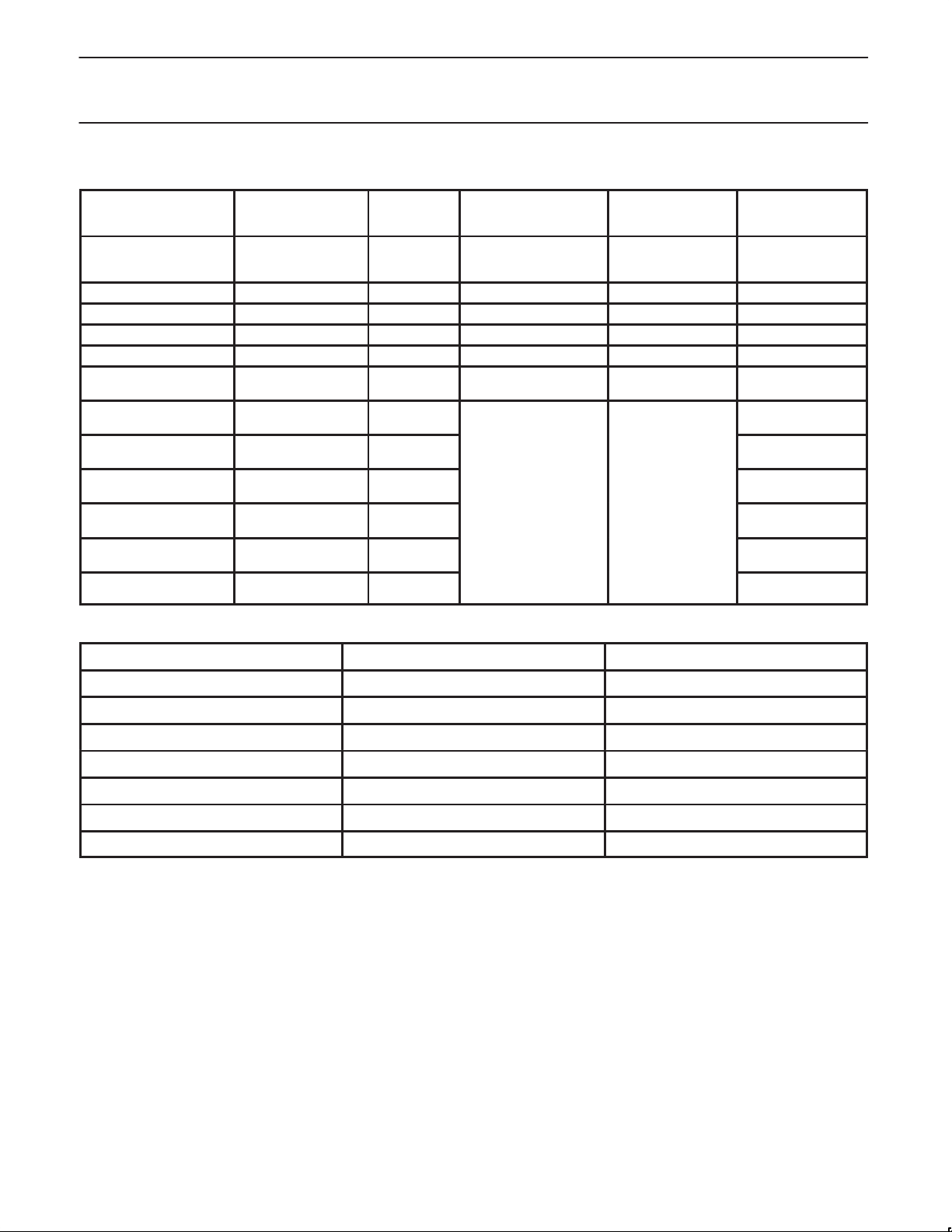
Table 6. SCC0 Interrupts (Interrupt structure is the same except for bit locations for all 4 SCCs)
Individual Enable Bit
Potential SCC0 Interrupt
Rx Character Available – RR0[0]
SDLC EOF – RR1[7]
CRC/Framing Error – RR1[6]
Rx Overrun – RR1[5]
Parity Error WR1[2] RR1[4]
Tx Buffer Empty See WR1[1] RR0[2] Tx Interrupt Enable
Break/Abort Break/Abort IE
Tx Underrun/EOM Tx Underrun/EOM IE
CTS CTS IE
SYNC/HUNT SYNC/HUNT IE
DCD DCD IE
Zero Count Zero Count IE
MMR Hex Offset
WR15[7]
WR15[6]
WR15[5]
WR15[4]
WR15[3]
WR15[1]
Source Bit
MMR Hex
Offset
RR0[7]
RR0[6]
RR0[5]
RR0[4]
RR0[3]
RR0[1]
Group Enable Bit(s)
MMR Hex Offset
WR1[4:3]
WR1[1]
Master External/ StatuspEven Channel
WR1[0]
Group Flag Bit MMR
Hex Offset
Even Channel Rx IP
RR3[5]
Even Channel Tx IP
RR3[4]
RR3[3]
Master Enable Bit
MMR Hex Offset
SCC0/1 Master
Interrupt Enable
WR9[3]
EXCEPTION/TRAPS PRECEDENCE
DESCRIPTION VECTOR ADDRESS ARBITRATION RANKING
Reset (h/w, watchdog, s/w) 0000–0003 0 (High)
Breakpoint 0004–0007 1
Trace 0008–000B 1
Stack Overflow 000C–000F 1
Divide by 0 0010–0013 1
User RETI 0014–0017 1
TRAP 0–15 (software) 0040–007F 1
1999 Mar 29
26
Page 27
Philips Semiconductors Preliminary specification
XA-SCCCMOS 16-bit communications microcontroller
EVENT INTERRUPTS
Description
Event Interrupt Source
High Priority Software
Interrupt 3
HSWR3
MMR
Flag Bit
Interrupt Vector
Address
00BF–00BC EHSWR3 PHSWR3 17
Enable Bit
(SFR)
Priority Register Bit
Field (SFR)
Arb. Rank
High Priority Software
Interrupt 2
High Priority Software
Interrupt 1
High Priority Software
Interrupt 0
SCP Port SPFG
Autobaud and V .54/2047 multiple OR from
SCC “SCC2/3” Interrupt multiple OR from
SCC “SCC0/1” Interrupt multiple OR from
DMA “DMAH” Interrupt multiple OR from DMA 009B– 0098 EDMAH PDMAH 8
DMA “DMAL” Interrupt multiple OR from DMA 0097–0094 EDMAL PDMAL 7
External Interrupt 2
(INT2
)
Timer 1 TF1
External Interrupt 1
(INT1
)
HSWR2
MMR
HSWR1
MMR
HSWR0
MMR
SCPCS[3]
MMR
Autobauds 3–0 &
V .54/2047 A and B
SCC2 & SCC3
SCC0 & SCC1
IE2
MMR
SFR
IE1
SFR
00BB–00B8 EHSWR2 PHSWR2 16
00B7–00B4 EHSWR1 PHSWR1 15
00B3–00B0 EHSWR0 PHSWR0 14
00AF–00AC ESCP PSCP 13
00AB–00A8 EAuto PAutoB 12
00A7–00A4 ESC23 PSC23 11
00A3–00A0 ESC01 PSC01 10
0093–0090 EX2 PX2 6
008F–008C ET1 PT1 5
008B–0088 EX1 PX1 4
Timer 0 TF0
External Interrupt 0
(INT0
)
SFR
IE0
SFR
0087–0084 ET0 PT0 3
0083–0080 EX0 PX0 2
SOFTWARE INTERRUPTS
DESCRIPTION FLAG BIT VECTOR ADDRESS ENABLE BIT INTERRUPT PRIORITY
Software Interrupt 1 SWR1 0100–0103 SWE1 (fixed at 1)
Software Interrupt 2 SWR2 0104–0107 SWE2 (fixed at 2)
Software Interrupt 3 SWR3 0108–010B SWE3 (fixed at 3)
Software Interrupt 4 SWR4 010C–010F SWE4 (fixed at 4)
Software Interrupt 5 SWR5 0110–01 13 SWE5 (fixed at 5)
Software Interrupt 6 SWR6 0114–01 17 SWE6 (fixed at 6)
Software Interrupt 7 SWR7 0118–011B SWE7 (fixed at 7)
1999 Mar 29
27
Page 28
Philips Semiconductors Preliminary specification
SYMBOL
PARAMETER
TEST CONDITIONS
UNIT
I
P
I
P
Idl
XA-SCCCMOS 16-bit communications microcontroller
ABSOLUTE MAXIMUM RATINGS
PARAMETER RATING UNIT
Operating temperature under bias –55 to +125 °C
Storage temperature range –65 to +150 °C
Voltage on any other pin to V
SS
Maximum IOL per I/O pin 15 mA
Power dissipation (based on package heat transfer, not device power consumption) 1.5 W
PRELIMINARY DC ELECTRICAL CHARACTERISTICS
VDD = 5.0V 10% or 3.3V 10% unless otherwise specified;
Tamb = –40°C to +85°C for industrial, unless otherwise specified.
DD
ower supply current, operating
5.0V, 30 MHz 75 120 mA
3.3V, 30 MHz 63 80 mA
–0.5 to VDD+0.5V v
LIMITS
MIN TYP MAX
5.0V, 30 MHz 62 100 mA
3.3V, 30 MHz 50 65 mA
5.0V, 3.0V 500 µA
DD
DD
IOL = 3.2mA, VDD = 4.5V 0.5 V
V
V
V
I
PDI
RAM
V
V
V
V
ID
IL
IH
IH1
OL
ower supply current,
Power supply current, Power Down mode
e mode
1
RAM keep-alive voltage 1.5 V
Input low voltage –0.5 0.22V
Input high voltage, except Xtal1, RST 2.2 V
Input high voltage to Xtal1, RST For both 3.0 & 5.0V 0.7 V
Output low voltage all ports
8
IOL = 1.0mA, VDD = 3.0V 0.4 V
V
OH1
Output high voltage, all ports IOH = –100µA, VDD = 4.5V 2.4 V
IOH = –30µA, VDD = 3.0V 2.0 V
V
OH2
Output high voltage, all ports IOH = 3.2mA, VDD = 4.5V 2.4 V
IOH = 1.0mA, VDD = 3.0V 2.2 V
C
IO
I
IL
I
LI
I
TL
Input/Output pin capacitance 15 pF
Logical 0 input current, all ports
Input leakage current, all ports
Logical 1 to 0 transition current, all ports
7
6
5
VIN = 0.45V –50 µA
VIN = VIL or V
IH
±10 µA
At VDD = 5.5V –650 µA
At VDD = 3.6V –250 µA
NOTES:
must be raised to within the operating range before power down mode is exited.
1. V
DD
2. Ports in quasi-bidirectional mode with weak pullup .
3. Ports in PUSH-PULL mode, both pullup and pulldown assumed to be the same strength.
4. In all output modes.
5. Port pins source a transition current when used in quasi-bidirectional mode and externally driven from 1 to 0. This current is highest when
VIN is approximately 2V .
6. Measured with port in high impedance mode.
7. Measured with port in quasi-bidirectional mode.
8. Under steady state (non-transient) conditions, I
Maximum I
Maximum I
Maximum total I
If I
exceeds the test condition, VOL may exceed the related specification. Pins are not guaranteed to sink current greater than the listed
OL
test conditions.
per port pin: 15mA (*NOTE: This is 85°C specification for VDD = 5V.)
OL
per 8-bit port: 26mA
OL
for all outputs: 71mA
OL
must be externally limited as follows:
OL
1999 Mar 29
28
Page 29
Philips Semiconductors Preliminary specification
XA-SCCCMOS 16-bit communications microcontroller
PRELIMINARY AC ELECTRICAL CHARACTERISTICS (5.0V 10%)
= 5.0V 10%, T
V
DD
= –40C to +85C (industrial)
amb
1
LIMITS
SYMBOL FIGURE PARAMETER MIN MAX UNIT
All Cycles
F
t
C
t
CHCX
t
CLCX
t
CLCH
t
CHCL
t
AVSL
t
CHAH
t
CHAV
t
CHSH
t
CHSL
t
CODH
t
CPWH
t
CPWL
C
13, 14, 16,
20, 21, 22
13, 21 CAS Pulse Width Low tC – 10 – ns
System Clock Frequency 0 30 MHz
25 System Clock Period = 1/F
C
33.33 – ns
25 XTALIN High Time tC* 0.5 – ns
25 XTALIN Low Time tC* 0.4 – ns
25 XTALIN Rise Time – 5 ns
25 XTALIN Fall Time – 5 ns
All Address Valid to Strobe low tC – 21 – ns
All Address hold after CLKOUT rising edge
9
1 – ns
All Delay from CLKOUT rising edge to address valid – 25 ns
All Delay from CLKOUT rising edge to Strobe High
All Delay from CLKOUT rising edge to Strobe Low
26 ClkOut Duty Cycle High (into 40pF max.)
(See Warning Note 5 on page 31.)
9
9
t
CHCX
1
1
–7 t
21 ns
19 ns
+3 ns
CHCX
CAS Pulse Width High tC – 12 – ns
All DRAM cycles
t
RP
24 RAS precharge time, thus minimum RAS high time
8
(n * tC) –16
– ns
note 8
Generic Data Read Only
t
AHDR
9, 16 Address hold (A19–A1 only, not A0) after CS, BLE, BHE rise at end
of Generic Data Read Cycle (not code fetch)
tC –12 – ns
Data Read and Instruction Fetch Cycles
t
DIS
9, 10,
12–14, 16,
Data In Valid setup to ClkOut rising edge 25 – ns
17, 20, 21
t
DIH
t
OHDE
10, 12, 13,
16, 20, 21
Data In Valid hold after ClkOut rising edge
OE high to XA Data Bus Driver Enable tC – 14 – ns
2
0 – ns
Write Cycles
t
CHDV
t
DVSL
t
SHAH
t
SHDH
11, 16 Minimum Address Hold Time after strobe goes inactive
Clock High to Data Valid – 25 ns
Data Valid prior to Strobe Low tC – 23 – ns
tC – 25
– ns
Data hold after strobes (CS and BHE/BLE) high tC – 25 – ns
Refresh
t
CLRL
21 CAS low to RAS low tC – 15 – ns
Wait Input
t
t
WS
WH
24 WAIT setup (stable high or low) to CLKOUT rising edge 20 – ns
24 WAIT hold (stable high or low) after CLKOUT rising edge 0 – ns
NOTE:
1. See notes after the 3.3V AC timing table.
1999 Mar 29
29
Page 30
Philips Semiconductors Preliminary specification
XA-SCCCMOS 16-bit communications microcontroller
AC ELECTRICAL CHARACTERISTICS (3.3V 10%)
VDD = 3.3V 10%, T
SYMBOL FIGURE PARAMETER
All Cycles
F
C
t
C
t
CHCX
t
CLCX
t
CLCH
t
CHCL
t
AVSL
t
CHAH
t
CHAV
t
CHSH
t
CHSL
t
CODH
t
CPWH
t
CPWL
13, 14, 16,
All DRAM cycles
t
RP
Generic Data Read Only
t
AHDR
Data Read and Instruction Fetch Cycles
t
DIS
t
DIH
t
OHDE
12–14, 16,
10, 12, 13,
Write Cycles
t
CHDV
t
DVSL
t
SHAH
t
SHDH
Refresh
t
CLRL
Wait Input
t
WS
t
WH
NOTES:
1. On a 16 bit bus, if only one byte is being written, then only one of BLE
goes active for all (odd or even address) accesses. BHE_CASH will not go active during any accesses on an 8 bit bus.
2. The bus timing is designed to make meeting hold time very straightforward without glue logic. On all generic reads and fetches, in order to
meet hold time, the slave device should hold data valid on the bus until the earliest of CS, BHE/BLE, OE, goes high (inactive), or until the
address changes. On all FPM DRAM reads and fetches, hold data valid on the bus until the earliest of RAS
(inactive.) On all EDO DRAM reads and fetches, hold data valid on the bus until a new CAS
3. To avoid tri-state fights during read cycles and fetch cycles, do not drive data bus until OE
= –40C to +85C (industrial)
amb
LIMITS
MIN MAX
25 System Clock (internally called CClk) Frequency 0 30 MHz
25 System Clock Period = 1/FC 33.33 – ns
25 XTALIN High Time tC* 0.5 – ns
25 XTALIN Low Time tC* 0.4 – ns
25 XTALIN Rise Time – 5 ns
25 XTALIN Fall Time – 5 ns
All Address Valid to Strobe low tC – 21 – ns
All Address hold after CLKOUT rising edge
9
1 – ns
All Delay from CLKOUT rising edge to address valid – 30 ns
All Delay from CLKOUT rising edge to Strobe High
All Delay from CLKOUT rising edge to Strobe Low
26 ClkOut Duty Cycle High (into 40pF max.)
(See Warning Note 5 on page 31.)
9
9
1 28 ns
1 25 ns
t
CHCX
–7 t
+3 ns
CHCX
CAS Pulse Width High tC – 12 – ns
20, 21, 22
13, 21 CAS Pulse Width Low tC – 10 – ns
24 RAS precharge time, thus minimum RAS high time
8
(n * tC) –16
– ns
note 8
9, 16 Address hold (A19–A1 only, not A0) after CS, BLE, BHE rise at end
tC –12 – ns
of Generic Data Read Cycle (not code fetch)
9, 10,
Data In Valid setup to ClkOut rising edge 32 – ns
17, 20, 21
Data In Valid hold after ClkOut rising edge
2
0 – ns
OE high to XA Data Bus Driver Enable tC – 19 – ns
16, 20, 21
Clock High to Data Valid – 30 ns
Data Valid prior to Strobe Low tC – 23 – ns
11, 16 Minimum Address Hold Time after strobe goes inactive tC – 25 – ns
Data hold after strobes (CS and BHE/BLE) high tC – 25 – ns
21 CAS low to RAS low tC – 15 – ns
24 WAIT setup (stable high or low) prior to CLKOUT rising edge 25 – ns
24 WAIT hold (stable high or low) after CLKOUT rising edge 0 – ns
_CASL or BHE_CASH will go active. On an 8 bit bus, BLE_CASL
, CAS, or OE goes high
is asserted, or until OE goes high (inactive.)
goes active
UNIT
1999 Mar 29
30
Page 31

Philips Semiconductors Preliminary specification
XA-SCCCMOS 16-bit communications microcontroller
4. To meet hold time, EDO DRAM drives data onto the bus until OE
rises, or until a new falling edge of CAS.
5. WARNING: ClkOut is specified at 40pF max. More than 40pf on ClkOut may significantly degrade the ClkOut waveform. Load capacitance
for all outputs (except ClkOut) = 80pF.
6. Not all combinations of bus timing configuration values result in valid bus cycles. Please refer to the
XA-SCC User Manual
for details.
7. When code is being fetched on the external bus, a burst mode fetch is used. This burst can be from 2 to 16 bytes long. On a 16 bit bus,
A3–A1 are incremented for each new word of the burst. On an 8 bit bus, A3–A0 are incremented for each new byte of the burst code fetch.
is specified as the minimum high time (thus inactive) on each of the 5 individual CS_RAS[5:1] pins when such pin is programmed in the
8. t
RP
memory controller to service DRAM. The number of CClks (system clocks) in t
equation in the AC tables. Regardless of what value is programmed into the control register, n will never be less than 2 clocks. Thus at
30MHz system clock, the minimum value for RAS precharge is t
frequency F
9. The MIN value for this parameter is guaranteed by design and is not tested in production to the specified limit. In those cases where a
, is slowed down, tC (system clock period) of course becomes greater, and thus tRP becomes greater.
C
= ((2 * tC) –16) = ((2 * 33.33) – 16) = 50.6ns. As the system clock
RP
is programmable, and is represented by n in the t
RP
RP
maximum value is specified in the table for this parameter, it is tested.
1999 Mar 29
31
Page 32
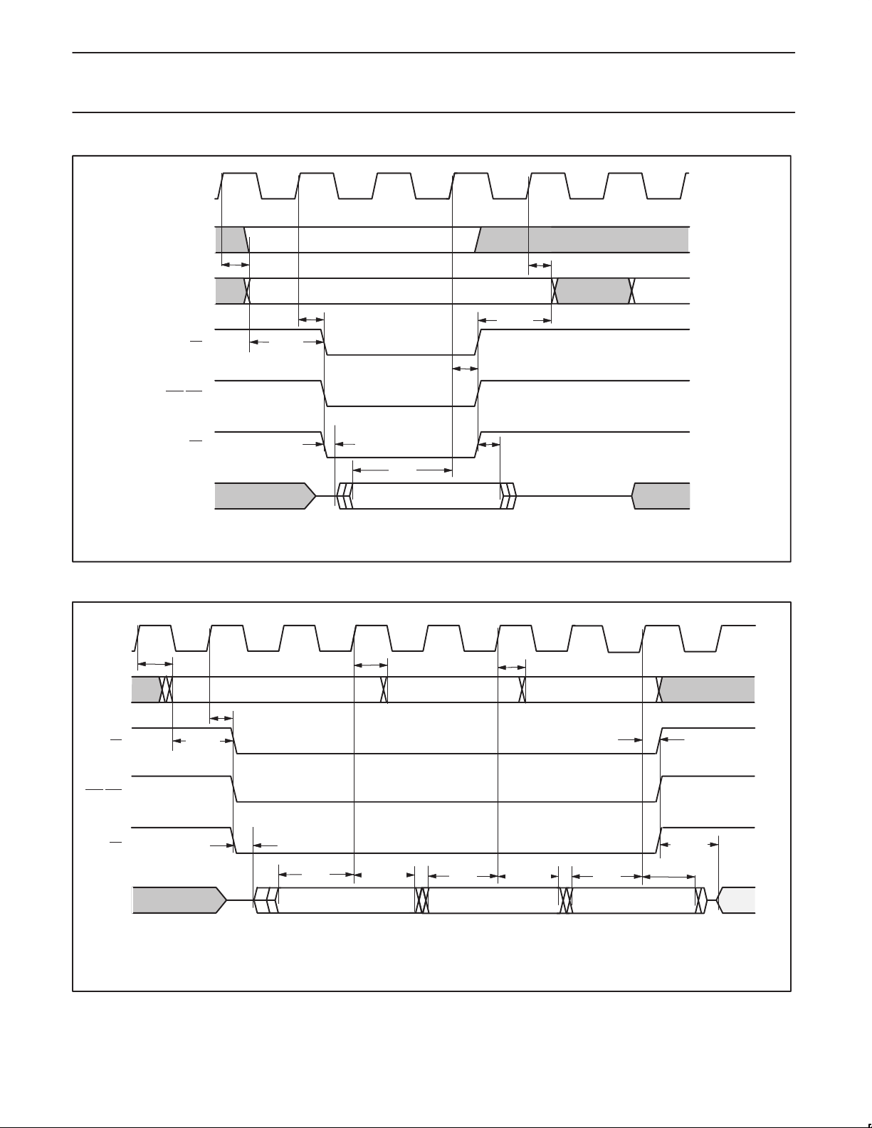
Philips Semiconductors Preliminary specification
XA-SCCCMOS 16-bit communications microcontroller
CLKOUT
A0
t
CHAV
A19–A1
t
CHSL
t
CS
BHE/BLE
OE
D15–D0
AVSL
NOTE 3
t
CHSH
t
DIS
NOTE: On Generic Data Reads, A0 can terminate a full clock period before A19–A1,
and therefore should not be used on some peripheral devices.
Figure 9. Generic (SRAM, ROM, Flash, IO Devices, etc.) Read on 16 Bit Bus
CLKOUT
A[19:0]
t
CHAV
ADDRESS ADDRESS + 2
t
CHAV
t
AHDR
t
DIH
(NOTE 2)
t
CHAV
t
CHAH
(DOES NOT INCLUDE A0)
ADDRESS + 4
SU01130
t
CHSL
t
NOTE 3
AVSL
t
t
DIS
DIH
NOTE 2
t
DIS
t
DIH
NOTE 2
CS
/BLE
BHE
OE
D[15:0]
NOTE: The processor can prefetch from one to eight words.
NOTE 2: To meet the required Data In Hold time, data should be held on the bus at least until the earliest of CS, BHE, BLE, OE goes high, or until the address changes,
whichever comes first.
DRIVEN BY XA
t
CHSH
t
(NOTE 2)
t
DIS
DIH
Figure 10. Generic Memory (SRAM, ROM, Flash, etc.) Burst Code Fetch on 16 Bit Bus
1999 Mar 29
32
t
OHDE
DRIVEN
BY XA
SU01131
Page 33
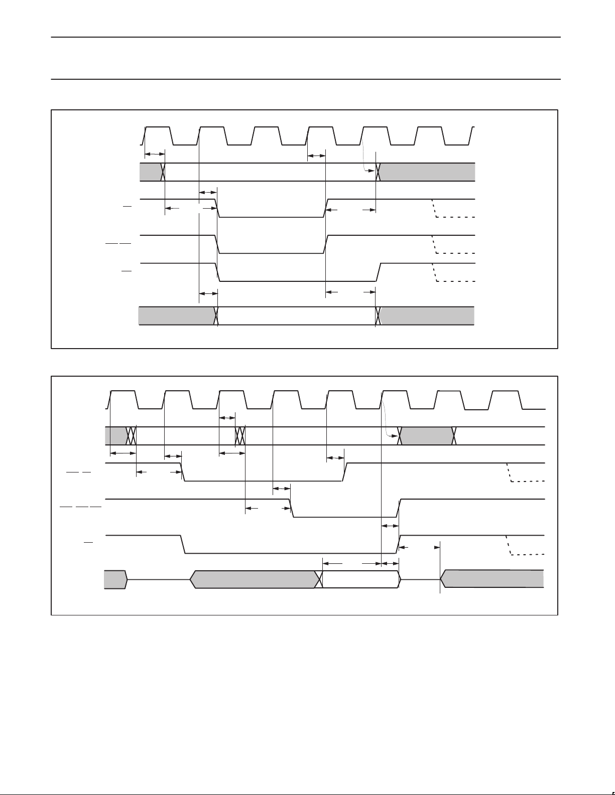
Philips Semiconductors Preliminary specification
XA-SCCCMOS 16-bit communications microcontroller
CLKOUT
t
CS
CHAV
A
t
CHSL
t
AVSL
t
CHSH
t
SHAH
CLKOUT
RAS (CS)
CAS
A
t
CHAV
(BHE/BLE)
BHE/BLE
WE
NOTE 1
t
t
CHDV
D
SHDH
SU01132
Figure 11. Generic (SRAM, IO Devices, etc.) W rite
t
CHAH
RAS ADDRESS CAS ADDRESS
t
CHAV
t
AVSL
t
CHSL
t
CHSH
t
CHSH
t
AVSL
t
CHSL
OE
1999 Mar 29
t
OHDE
t
t
DIS
D
VALID DATA
DIH
NOTE 2
SU01133
Figure 12. DRAM Single Read Cycle
33
Page 34
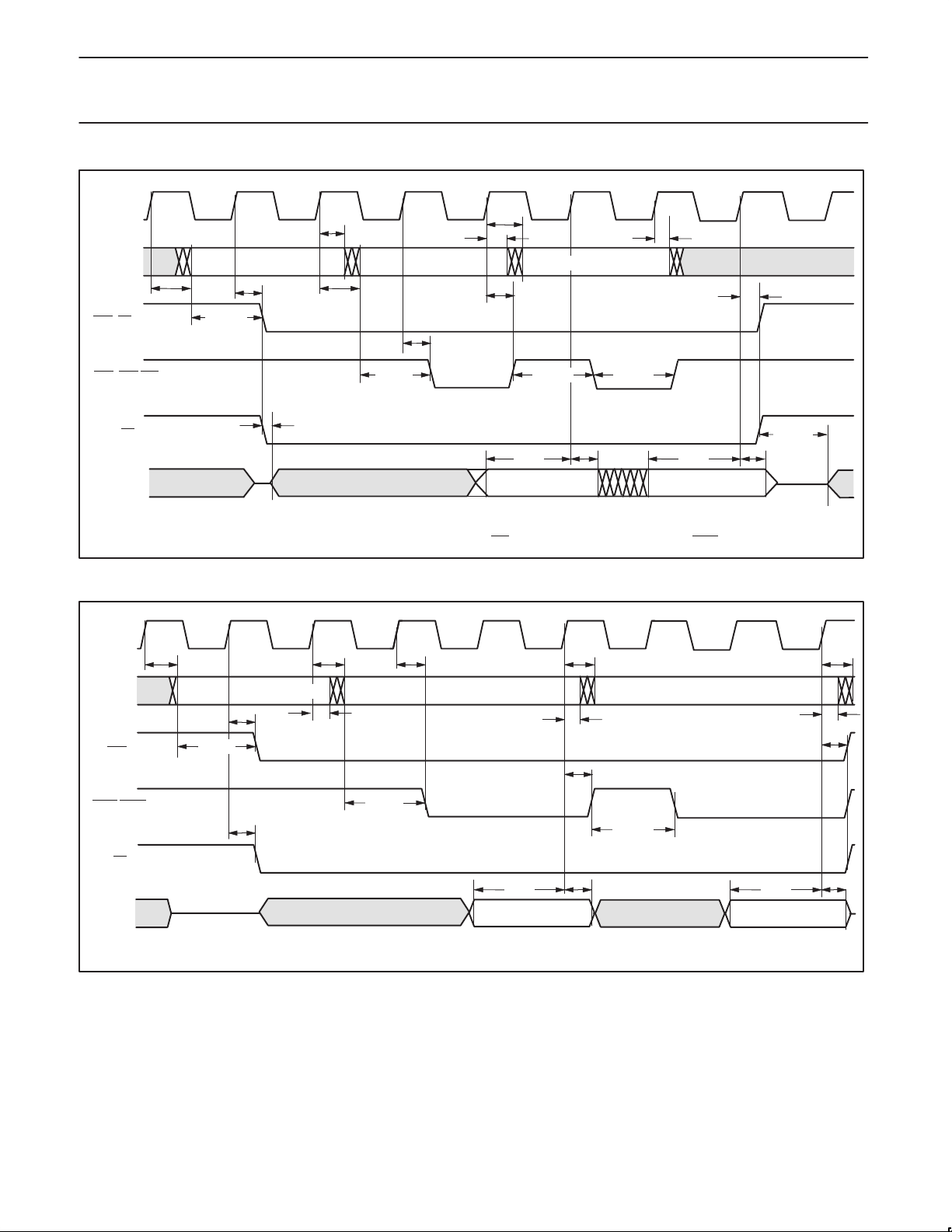
Philips Semiconductors Preliminary specification
XA-SCCCMOS 16-bit communications microcontroller
CLKOUT
t
CHAV
CAS ADDRESS + 2
t
CHSH
t
CHAH
t
CHSH
t
CHAV
RAS (CS)
t
CHAH
A
RAS ADDRESS CAS ADDRESS
t
CHAV
tAVSL
t
CHSL
t
CHAH
t
CHSL
CAS (BHE/BLE)
D[15:0]
CLKOUT
RAS
CASL/CASH
D[15:0]
OE
DRIVEN BY XA DRIVEN BY SLAVE DEVICE
NOTE 3
t
AVSL
t
CPWH
t
DIS
WORD
(from CAS ADDR)
4 Byte Fetch (1 word = 2 bytes) is shown on 16 bit bus, burst can be 2 to 16 bytes (1 to 8 words.)
Note 4: To meet hold time, EDO DRAM drives valid Data until OE
rises, or until new falling edge of CAS.
Figure 13. DRAM EDO Burst Code Fetch on 16 Bit Bus
t
CHAV
t
CHAH
t
DIS
INSTRUCTION
OE
t
CHAV
A
t
CHSL
t
AVSL
t
CHAV
RAS ADDRESS
t
CHSL
t
CHAH
t
CHSL
t
CAS ADDRESS CAS ADDRESS + 2
AVSL
NOTE 4
t
CHSH
NOTE 2
t
CPWL
t
CPWH
t
DIS
WORD
(from CAS ADDR + 2)
t
OHDE
NOTE 4
SU01134
t
CHAV
t
CHAH
t
CHSH
t
DIS
INSTRUCTION
NOTE 2
NOTE: The processor can prefetch from one to eight words (1 word = 2 bytes)
Figure 14. DRAM FPM (Fast Page Mode) Burst Code Fetch
1999 Mar 29
SU01135
34
Page 35
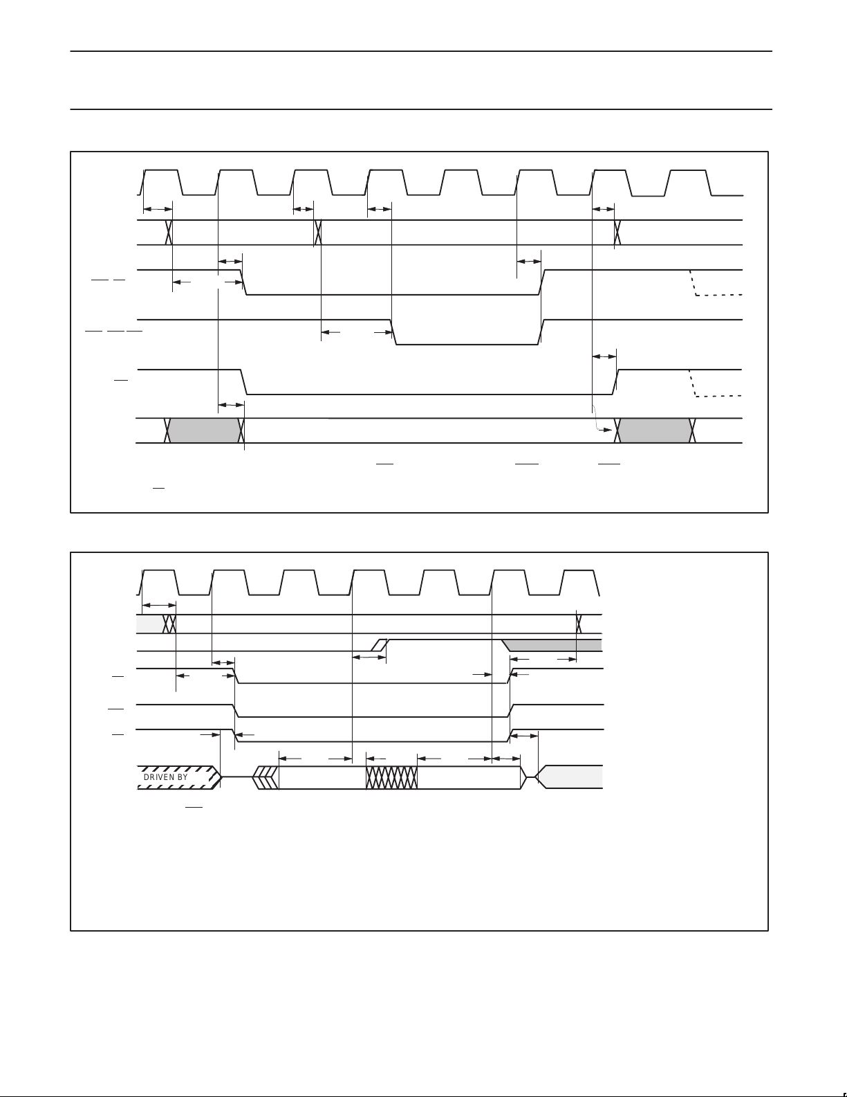
Philips Semiconductors Preliminary specification
XA-SCCCMOS 16-bit communications microcontroller
CLKOUT
t
CHAV
A
t
CHDV
t
AVSL
(CS)
RAS
(BHE/BLE)
CAS
WE
D
NOTE: If only one byte is being written, then only the corresponding CAS
both even and odd addressed bytes.
:OE is inactive during all writes.
t
CHAH
RAS ADDRESS CAS ADDRESS
t
CHSL
Figure 15. DRAM Write (on 16 Bit Bus, also 8 Bit Write on 8 Bit Bus)
CLKOUT
t
CHAV
A19–A1
CS
A0
t
EVEN BYTE ADDRESS ODD BYTE ADDRESS
t
AVSL
CHSL
t
CHSL
t
AVSL
VALID DATA
t
CHAH
t
CHSH
NOTE 1
t
CHSH
signal goes active. On 8 bit bus, CASH is inactive, and CASL goes active for
t
CHAV
t
AHDR
t
CHSH
SU01136
BLE
OE
D7–D0
On all cycles on 8 bit bus, BHE remains high (inactive).
WARNING: On the external bus, ALL XA–SCC reads are 16 bit Reads. If the CPU instruction only specifies 8 bits, then the CPU uses the appropriate byte, and discards the extra
byte. Thus “8 Bit Reads” and “16 bit Reads” appear to be identical on the bus. On an 8 bit bus, this will appear as two consecutive 8 bit reads even though the CPU will only use one
of the two bytes.
WARNING: Some 8 bit I/O devices (especially FIFOs) cannot operate correctly with 2 bytes being Read for a 1 Byte Read. The most common (and least expensive) solution is to
operate these 8 bit devices on a 16 bit bus, and access them in software on all odd byte (or all even byte) boundaries. An added benefit of this technique is that byte reads are faster
than on an 8 bit bus, because only 1 word is fetched (a single read) instead of 2 consecutive bytes.
DRIVEN BY XA
NOTE 3
t
t
DIS
NOTE 2
t
DIS
DIH
NOTE 2
t
OHDE
DRIVEN
BY XA
Figure 16. Generic (SRAM, Flash, I/O Device, etc.) Read (16 Bit or 8 Bit) on 8 Bit Bus
1999 Mar 29
35
SU01137
Page 36
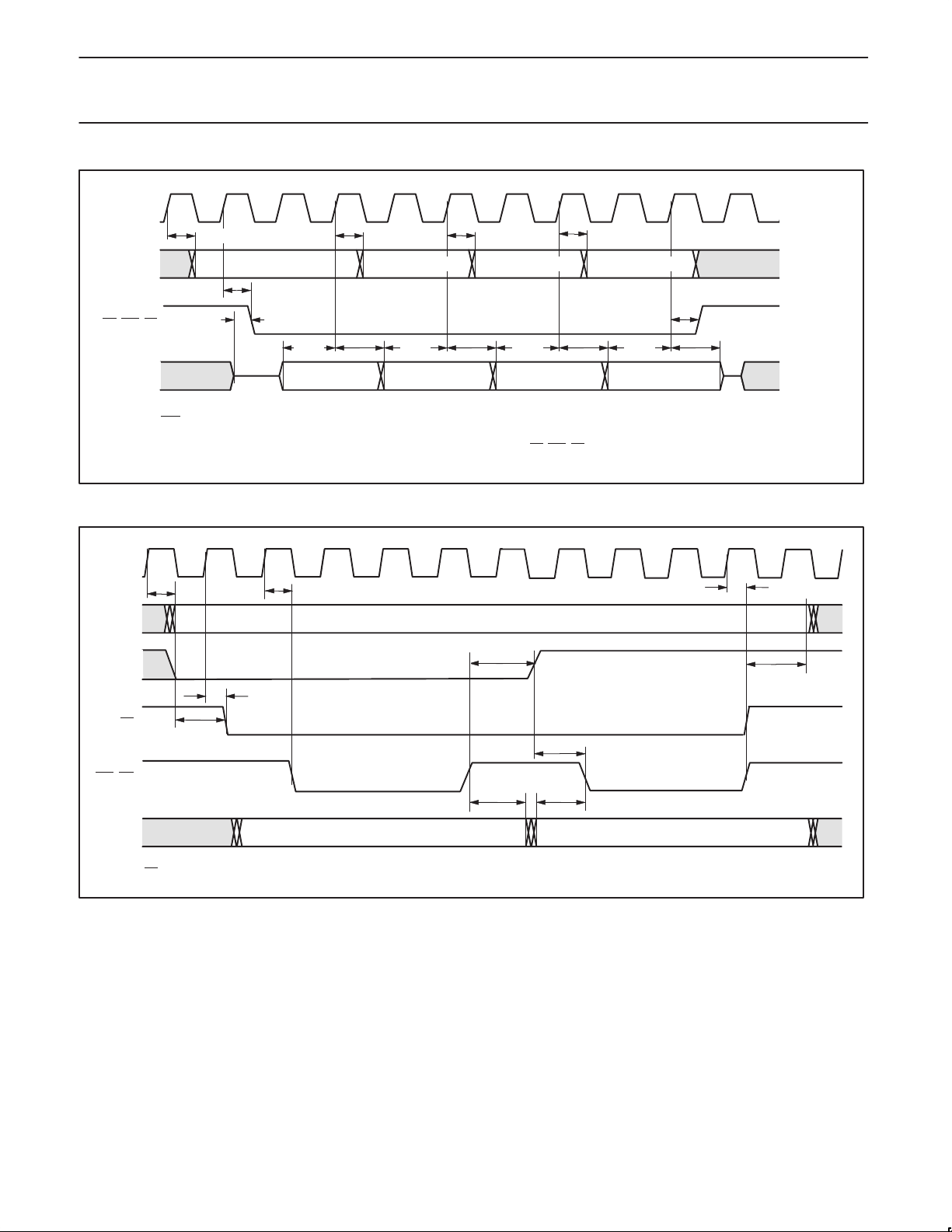
Philips Semiconductors Preliminary specification
XA-SCCCMOS 16-bit communications microcontroller
ClkOut
t
CHAV
t
CHAV
EVEN ADDRESS ADDRESS + 1 ADDRESS + 2 ADDRESS + 3
t
CHAV
OE, BLE, CS
D[7:0]
NOTES: BHE remains high (inactive) for all accesses on an 8 bit bus.
A burst code fetch can be from 1 to 8 words (1 word = 2 bytes), a 2 word fetch is shown here.
To meet the required Data In Hold time, data should be held on the bus at least until the earliest of CS
first.
NOTE 3
t
t
DIS
DIH
Note 2
t
DIS
t
DIH
Note 2
LS BYTE MS BYTE LS BYTE MS BYTE
Figure 17. Burst Code Fetch on 8 bit bus, Generic Memory
ClkOut
t
t
A19–A1
CHAV
A0
CHSL
t
SHAH
t
CHAV
t
CHAV
t
CHSH
t
t
DIS
DIH
Note 2
t
DIS
t
DIH
Note 2
, BLE, OE goes high, or until the address changes, whichever occurs
t
SHAH
t
CHSH
SU01138
CS
BLE, WE
D7–D0
t
OE
is inactive during all writes.
AVSL
t
CHSL
t
SHDH
Figure 18. Generic 16 Bit Write on 8 Bit Bus
t
AVSL
t
DVSL
SU01139
1999 Mar 29
36
Page 37
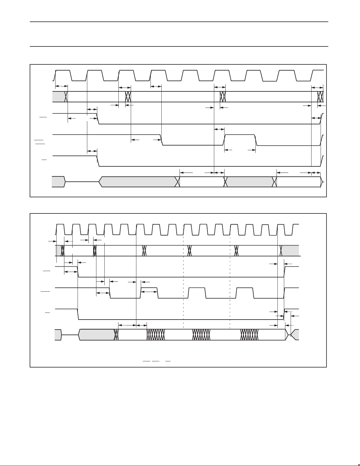
Philips Semiconductors Preliminary specification
XA-SCCCMOS 16-bit communications microcontroller
CLKOUT
A
RAS
CASL
(CASH STAYS HIGH)
OE
D[7:0]
t
CHAV
t
CHAV
RAS ADDRESS CAS ADDRESS EVEN CAS ADDRESS ODD
t
t
CHSL
t
AVSL
CHAH
t
CHSL
t
CHSL
t
AVSL
t
t
CHAH
t
DIS
LS BYTE
CHAV
t
CHSH
t
DIH
t
CPWH
(NOTE 2)
t
CHAV
t
CHAH
t
DIS
MS BYTE
t
CHSH
NOTE 2
Figure 19. 16 Bit Read on 8 Bit Bus, DRAM (both FPM and EDO)
1 23456789101112131415
ClkOut
t
t
CHSL
CHSL
t
AVSL
CHAH
CAS ADDR
(EVEN)
t
DIS
t
CHSH
(NOTE 2)
DIH
CAS ADDR
(ODD)
t
CPWH
CAS ADDR
(EVEN)
LS BYTE MS BYTE LS BYTE MS BYTE
t
CHAV
CASL
D7–D0
RAS
OE
A
RAS ADDR
t
AVSL
t
4 Byte Fetch is shown on 8 bit bus, burst can be 2 to 16 bytes.
Data bus is sampled on the rising edge of clock 6, and every three clocks thereafter (clocks 6, 9, 12, and 15 in this example).
NOTE 2: If data is held valid on the bus until the earliest of CAS
, RAS, or OE rises, then the hold time is met.
Figure 20. DRAM FPM (Fast Page Mode) Burst Code Fetch on 8 Bit Bus
CAS ADDR
(ODD)
(NOTE 2)t
t
DIH
t
CHSH
t
CHSH
SU01140
t
OHDE
SU01141
1999 Mar 29
37
Page 38
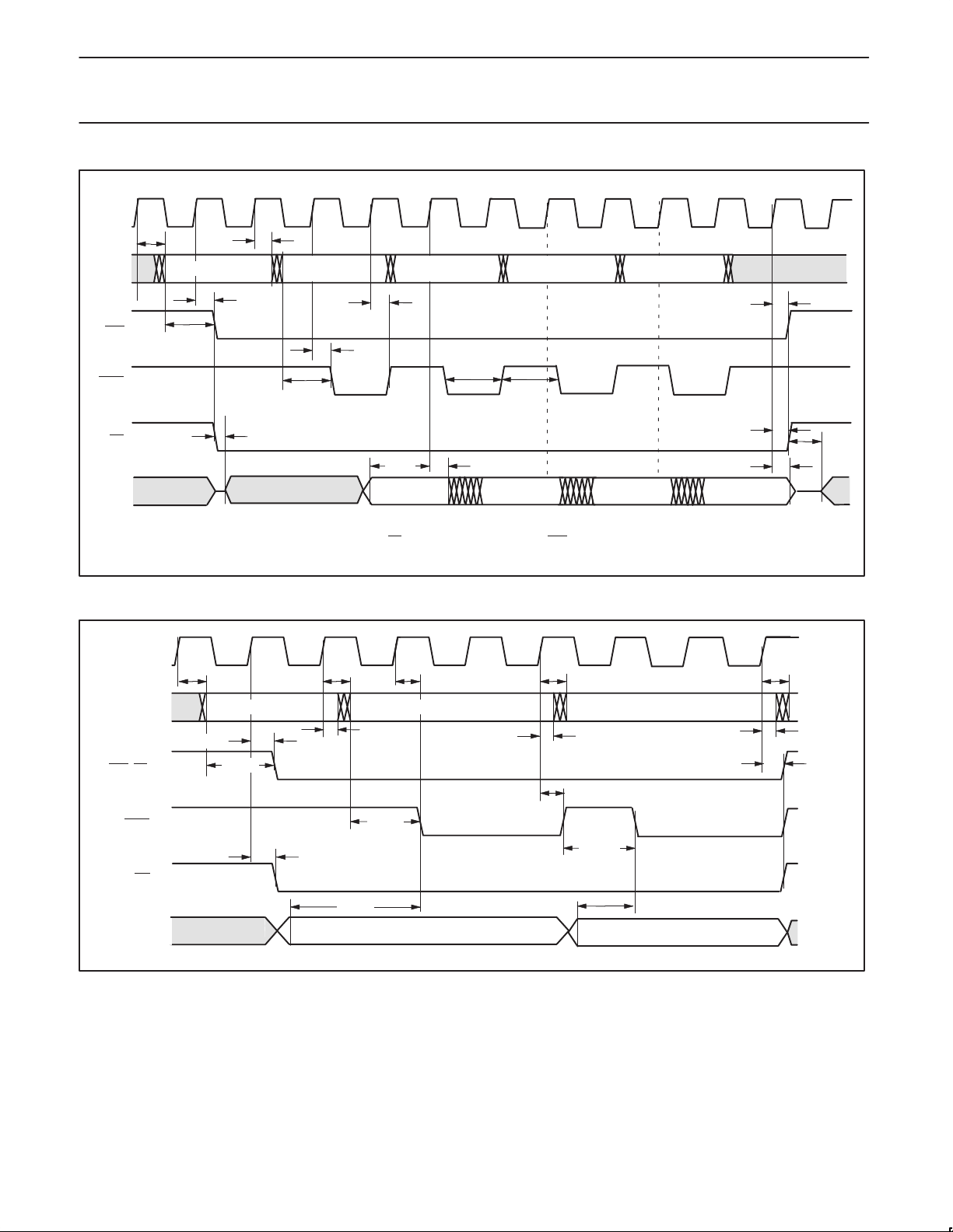
Philips Semiconductors Preliminary specification
XA-SCCCMOS 16-bit communications microcontroller
123456789101112
ClkOut
t
CHAH
RAS ADDRESS
t
AVSL
CAS ADDR
(EVEN)
t
CHSL
t
AVSL
t
CHSH
t
CHSL
t
DIS
DRIVEN BY SLAVE LS BYTE
CAS ADDR
(ODD)
t
CPWL
CAS ADDR
t
CPWH
(EVEN)
CAS ADDR
(ODD)
NOTE 4
MS BYTE LS BYTE MS BYTE
t
CHSH
t
CHSH
NOTE 4
t
OHDE
CASL
D7–D0
t
RAS
OE
CHAV
A
NOTE 3
DRIVEN
BY XA
4 Byte Fetch is shown on 8 bit bus, burst can be 2 to 16 bytes.
NOTE 4: To meet hold time, EDO DRAM drives Data until OE rises, or until a new falling edge of CAS.
Data Bus is sampled on rising edge of clock 6, and every 2 clocks thereafter (clocks 6, 8, 10, and 12 in this example).
Figure 21. EDO DRAM Burst Code Fetch on 8 Bit Bus
CLKOUT
RAS
(CS)
CASL
t
CHAV
A
RAS ADDRESS CAS ADDRESS (EVEN) CAS ADDRESS (ODD)
t
CHSL
t
AVSL
t
CHSL
t
CHAV
t
t
CHAH
CHSL
t
AVSL
t
CHAH
t
CHAV
WE
t
DVSL
D[7:0]
LS BYTE
Figure 22. DRAM 16 Bit Write on 8 Bit Bus (FPM or EDO DRAMs)
t
CHSH
t
CPWH
t
DVSL
MS BYTE
t
CHAH
t
CHSH
t
CHAV
SU01142
SU01143
1999 Mar 29
38
Page 39
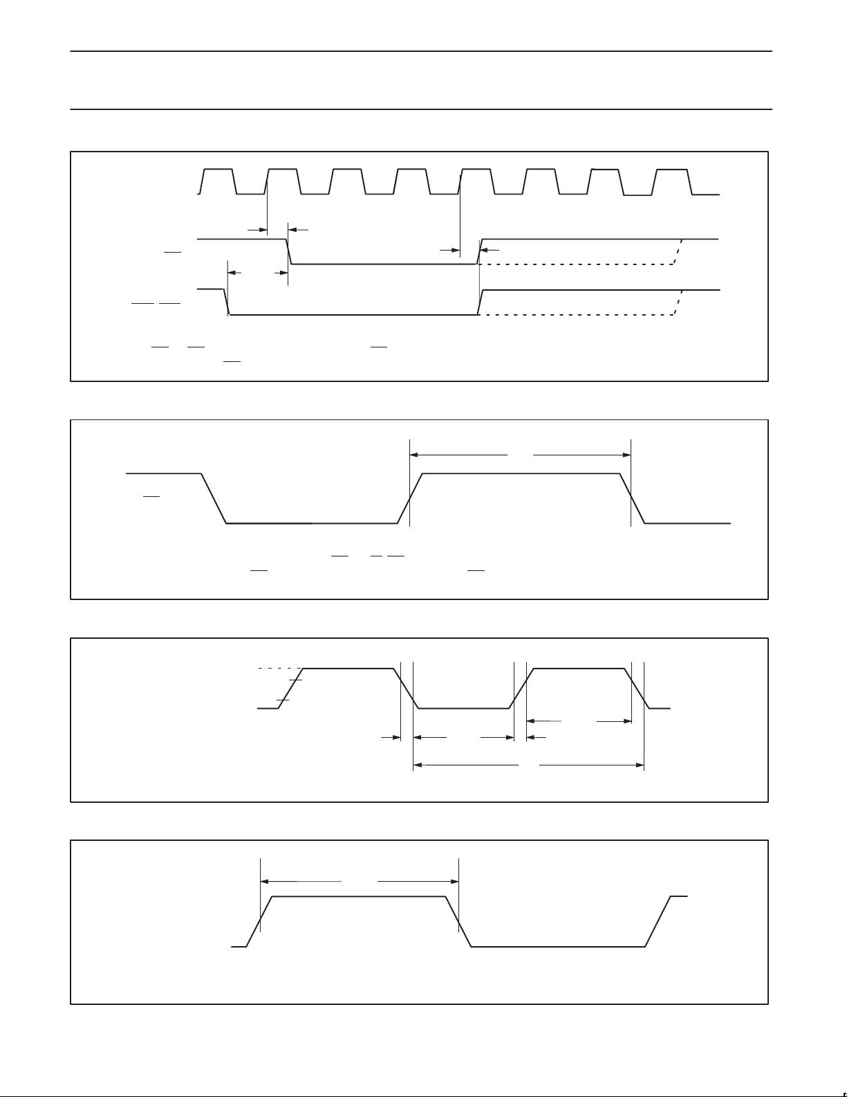
Philips Semiconductors Preliminary specification
XA-SCCCMOS 16-bit communications microcontroller
CLKOUT
t
CHSL
t
RAS
t
CLRL
CHSH
CASH, CASL
RAS and CAS terminate together. The active low portion of RAS can be programmed to last from 3 to 6 clock cycles.
The high portion of RAS
after Refresh can be programmed to last from 2 to 4 clock cycles. See Chapter 3 of
Figure 23. REFRESH
t
RP
RAS
NOTE: tRP min. is specified for each of the 5 individual RAS pins (CS_RAS[5:1]).
It is the minimum high time (thus RAS
inactive) between two DRAM bus cycles on the same RAS pin.
Figure 24. RAS Precharge Time
VDD – 0.5
XTALIN
0.45 V
0.2 V
0.7 V
DD
DD
– 0.1
t
CHCL
t
CLCX
XA–SCC User Manual
t
CHCX
t
CLCH
.
SU01144
SU01145
1999 Mar 29
ClkOut
Figure 25. External Clock Input Drive
t
CODH
WARNING: ClkOut is specified into 40 pF max, do not overload.
Figure 26. ClkOut Duty Cycle
39
t
C
SU01146
SU01147
Page 40
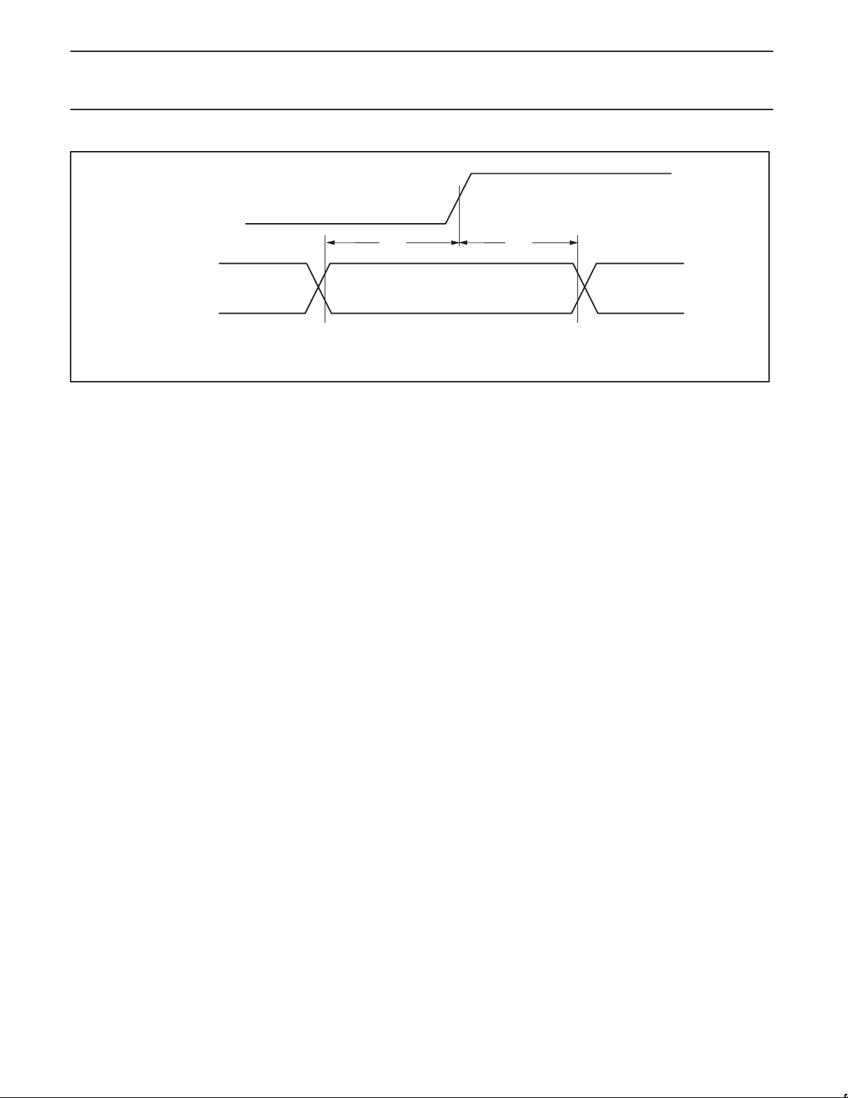
Philips Semiconductors Preliminary specification
XA-SCCCMOS 16-bit communications microcontroller
ClkOut
WAIT
t
WS
tWS – Setup time of WAIT to riasing edge of ClkOut.
tWH – Hold time of WAIT after ClkOut High.
Figure 27. External WAIT Pin T iming
t
WH
SU01148
1999 Mar 29
40
Page 41
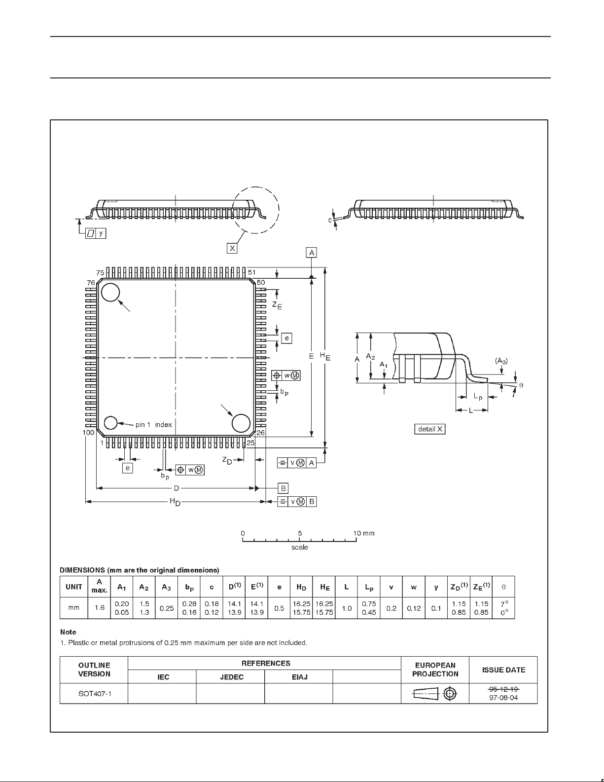
Philips Semiconductors Preliminary specification
XA-SCCCMOS 16-bit communications microcontroller
LQFP100: plastic low profile quad flat package; 100 leads; body 14 x 14 x 1.4 mm SOT407-1
mold mark
mold mark
1999 Mar 29
41
Page 42

Philips Semiconductors Preliminary specification
XA-SCCCMOS 16-bit communications microcontroller
Data sheet status
Data sheet
status
Objective
specification
Preliminary
specification
Product
specification
Product
status
Development
Qualification
Production
Definition
This data sheet contains the design target or goal specifications for product development.
Specification may change in any manner without notice.
This data sheet contains preliminary data, and supplementary data will be published at a later date.
Philips Semiconductors reserves the right to make chages at any time without notice in order to
improve design and supply the best possible product.
This data sheet contains final specifications. Philips Semiconductors reserves the right to make
changes at any time without notice in order to improve design and supply the best possible product.
[1]
[1] Please consult the most recently issued datasheet before initiating or completing a design.
Definitions
Short-form specification — The data in a short-form specification is extracted from a full data sheet with the same type number and title. For
detailed information see the relevant data sheet or data handbook.
Limiting values definition — Limiting values given are in accordance with the Absolute Maximum Rating System (IEC 134). Stress above one
or more of the limiting values may cause permanent damage to the device. These are stress ratings only and operation of the device at these or
at any other conditions above those given in the Characteristics sections of the specification is not implied. Exposure to limiting values for extended
periods may affect device reliability.
Application information — Applications that are described herein for any of these products are for illustrative purposes only. Philips
Semiconductors make no representation or warranty that such applications will be suitable for the specified use without further testing or
modification.
Disclaimers
Life support — These products are not designed for use in life support appliances, devices or systems where malfunction of these products can
reasonably be expected to result in personal injury . Philips Semiconductors customers using or selling these products for use in such applications
do so at their own risk and agree to fully indemnify Philips Semiconductors for any damages resulting from such application.
Right to make changes — Philips Semiconductors reserves the right to make changes, without notice, in the products, including circuits, standard
cells, and/or software, described or contained herein in order to improve design and/or performance. Philips Semiconductors assumes no
responsibility or liability for the use of any of these products, conveys no license or title under any patent, copyright, or mask work right to these
products, and makes no representations or warranties that these products are free from patent, copyright, or mask work right infringement, unless
otherwise specified.
Philips Semiconductors
811 East Arques Avenue
P.O. Box 3409
Sunnyvale, California 94088–3409
Telephone 800-234-7381
Copyright Philips Electronics North America Corporation 1999
All rights reserved. Printed in U.S.A.
Date of release: 03-99
Document order number: 9397 750 05491
1999 Mar 29
42
 Loading...