

Page 1

Cat. No. N138-E1-01
WT30
FA Wireless SS Terminal
Page 2

Authorized Distributor:
Cat. No. N138-E1-01 Note: Specifications subject to change without notice
Printed in Japan
0105-?M (0105) (?)
Page 3

Notice
(1) This manual may not be copied, reproduced, or reprinted, in whole or in part, without permission
from OMRON.
(2) The specifications listed within this manual may be revised without prior notice.
(3) The information in this manual was compiled with the utmost care. However, if you should find any
errors or inconsistencies, please contact the OMRON business office. Be sure to tell us the revi-
sion number of the manual in which you found the error.
Page 4

Introduction
OMRON products are manufactured for use according to proper procedures by a qualified operator
and only for the purposes described in this manual.
Thank you for purchasing this WT30 FA Wireless SS Terminal (also referred to as WT30 or WT30 Terminal in this manual).
The WT30 System consists of a Serial Master Station and I/O Slave Stations. The Serial Master Station is a wireless terminal that collects ON/OFF data using wireless communications and is connected
to a device with an RS-232C interface (e.g., a personal computer or PLC). I/O Slave Stations with I/O
terminals can also be connected to a DeviceNet-compatible WD30 Master.
Intended Audience
This manual is intended for the following readers.
• Persons in charge of introducing FA devices
• Persons who design FA systems
• Persons who install or connect FA devices
• Persons who manage working FA installations
Persons who use this product must have sufficient knowledge of electrical systems (i.e., an electrical
engineer or the equivalent).
i
Page 5

READ AND UNDERSTAND THIS DOCUMENT
Please read and understand this document before using the product. Please consult your OMRON representative if you
have any questions or comments.
WARRANTY
OMRON’s exclusive warranty is that the products are free from defects in materials and workmanship for a period of one
year (or other period if specified) from date of sale by OMRON.
OMRON MAKES NO WARRANTY OR REPRESENTATION, EXPRESS OR IMPLIED, REGARDING NONINFRINGEMENT, MERCHANTABILITY, OR FITNESS FOR PARTICULAR PURPOSE OF THE PRODUCTS. ANY BUYER
OR USER ACKNOWLEDGES THAT THE BUYER OR USER ALONE HAS DETERMINED THAT THE PRODUCTS WILL
SUITABLY MEET THE REQUIREMENTS OF THEIR INTENDED USE. OMRON DISCLAIMS ALL OTHER WARRANTIES,
EXPRESS OR IMPLIED.
LIMITATIONS OF LIABILITY
OMRON SHALL NOT BE RESPONSIBLE FOR SPECIAL, INDIRECT, OR CONSEQUENTIAL DAMAGES, LOSS OF
PROFITS OR COMMERCIAL LOSS IN ANY WAY CONNECTED WITH THE PRODUCTS, WHETHER SUCH CLAIM IS
BASED ON CONTRACT, WARRANTY, NEGLIGENCE, OR STRICT LIABILITY.
In no event shall responsibility of OMRON for any act exceed the individual price of the product on which liability is
asserted.
IN NO EVENT SHALL OMRON BE RESPONSIBLE FOR WARRANTY, REPAIR, OR OTHER CLAIMS REGARDING THE
PRODUCTS UNLESS OMRON’S ANALYSIS CONFIRMS THAT THE PRODUCTS WERE PROPERLY HANDLED,
STORED, INSTALLED, AND MAINTAINED AND NOT SUBJECT TO CONTAMINATION, ABUSE, MISUSE, OR
INAPPROPRIATE MODIFICATION OR REPAIR.
SUITABILITY FOR USE
THE PRODUCTS CONTAINED IN THIS DOCUMENT ARE NOT SAFETY RATED. THEY ARE NOT DESIGNED OR
RATED FOR ENSURING SAFETY OF PERSONS, AND SHOULD NOT BE RELIED UPON AS A SAFETY COMPONENT
OR PROTECTIVE DEVICE FOR SUCH PURPOSES. Please refer to separate catalogs for OMRON's safety rated
products.
OMRON shall not be responsible for conformity with any standards, codes, or regulations that apply to the combination of
products in the customer’s application or use of the product.
At the customer’s request, OMRON will provide applicable third party certification documents identifying ratings and
limitations of use that apply to the products. This information by itself is not sufficient for a complete determination of the
suitability of the products in combination with the end product, machine, system, or other application or use.
The following are some examples of applications for which particular attention must be given. This is not intended to be an
exhaustive list of all possible uses of the products, nor is it intended to imply that the uses listed may be suitable for the
products:
• Outdoor use, uses involving potential chemical contamination or electrical interference, or conditions or uses not
described in this document.
• Nuclear energy control systems, combustion systems, railroad systems, aviation systems, medical equipment,
amusement machines, vehicles, safety equipment, and installations subject to separate industry or government
regulations.
• Systems, machines, and equipment that could present a risk to life or property.
Please know and observe all prohibitions of use applicable to the products.
ii
Page 6

NEVER USE THE PRODUCTS FOR AN APPLICATION INVOLVING SERIOUS RISK TO LIFE OR PROPERTY WITHOUT
ENSURING THAT THE SYSTEM AS A WHOLE HAS BEEN DESIGNED TO ADDRESS THE RISKS, AND THAT THE
OMRON PRODUCT IS PROPERLY RATED AND INSTALLED FOR THE INTENDED USE WITHIN THE OVERALL
EQUIPMENT OR SYSTEM.
PERFORMANCE DATA
Performance data given in this document is provided as a guide for the user in determining suitability and does not
constitute a warranty. It may represent the result of OMRON’s test conditions, and the users must correlate it to actual
application requirements. Actual performance is subject to the OMRON Warranty and Limitations of Liability.
CHANGE IN SPECIFICATIONS
Product specifications and accessories may be changed at any time based on improvements and other reasons.
It is our practice to change model numbers when published ratings or features are changed, or when significant
construction changes are made. However, some specifications of the product may be changed without any notice. When in
doubt, special model numbers may be assigned to fix or establish key specifications for your application on your request.
Please consult with your OMRON representative at any time to confirm actual specifications of purchased products.
DIMENSIONS AND WEIGHTS
Dimensions and weights are nominal and are not to be used for manufacturing purposes, even when tolerances are shown.
ERRORS AND OMISSIONS
The information in this document has been carefully checked and is believed to be accurate; however, no responsibility is
assumed for clerical, typographical, or proofreading errors, or omissions.
PROGRAMMABLE PRODUCTS
OMRON shall not be responsible for the user’s programming of a programmable product, or any consequence thereof.
COPYRIGHT AND COPY PERMISSION
This document shall not be copied for sales or promotions without permission.
This document is protected by copyright and is intended solely for use in conjunction with the product. Please notify us
before copying or reproducing this document in any manner, for any other purpose. If copying or transmitting this document
to another, please copy or transmit it in its entirety.
iii
Page 7

Approved Standards
Conforming Wireless Standards:
Japan: ARIB STD-T66
USA: FCC part 15.247
Europe: EN 300 440-2
Conforming Safety Standards: UL508 (Listing)
Conforming EMC Standards: EN 301 489-3
Conforming EMF Standards: EN 50371
Applicable Countries
This product has been approved for wireless standards in the countries listed
below. This product cannot be used in any other countries.
Austria, Belgium, Cyprus, Czech Republic, Denmark, Estonia, Finland,
France, Germany, Greece, Hungry, Iceland, Ireland, Italy, Japan, Latvia,
Lithuania, Luxembourg, Malta, Netherlands, Norway, Poland, Portugal, Slovakia, Slovenia, Spain, Sweden, Switzerland, UK, USA
Conformance to EN Standards
Use a DC power line less than 3 m to conform to EN standards. If a power line
of 3 m or longer is required, extend the length at the Switching Power Supply’s
primary side (i.e., the AC power line).
EN 60950-1
EN 301 489-17
Conformance to UL Standards
Always use a Class 2 power supply to conform to UL standards.
FCC Notice
This device complies with part 15 of the FCC Rules. Operation is subject to
the following two conditions: (1) This device may not cause harmful interference, and (2) this device must accept any interference received, including
interference that may cause undesired operation.
Caution
To ensure that the WLAN transmitter complies with current FCC regulations
limiting both maximum RF output power and human exposure to radio frequency radiation, a separation distance of at least 20 cm must be maintained
between the Unit’s antenna and the body of the user and any nearby persons
at all times and in all applications and uses.
Notice
Changes or modificatiaons not expressly approved by the party responsible
for compliance could void the user’s authority to operate the equipment.
iv
Page 8
CE NOTICE
English Hereby, Omron Corporation, declares that this WT30 is in
compliance with the essential requirements and other relevant
provisions of Directive 1995/5/EC.
Finnish Omron Corporation vakuuttaa täten että WT30 tyyppinen laite
on direktiivin 1995/5/EY oleellisten vaatimusten ja sitä
koskevien direktiivin muiden ehtojen mukainen.
Dutch Bij deze verklaart Omron Corporation dat deze WT30 voldoet
aan de essentiële eisen en aan de overige relevante bepalingen
van Richtlijn 1995/5/EC.
Swedish Härmed intygar Omron Corporation att denna WT30 står I
överensstämmelse med de väsentliga egenskapskrav och övriga
relevanta bestämmelser som framgår av direktiv 1995/5/EG.
Danish Undertegnede Omron Corporation erklærer herved, at følgende
udstyr WT30 overholder de væsentlige krav og øvrige relevante
krav i direktiv 1995/5/EF
German Hiermit erklärt Omron Corporation die Übereinstimmung des
Gerätes WT30 mit den grundlegenden Anforderungen und den
anderen relevanten Festlegungen der Richtlinie 1995/5/EG.
Italian Con la presente Omron Corporation dichiara che questo WT30 è
conforme ai requisiti essenziali ed alle altre disposizioni
pertinenti stabilite dalla direttiva 1995/5/CE.
Spanish Por medio de la presente Omron Corporation declara que el
WT30 cumple con los requisitos esenciales y cualesquiera otras
disposiciones aplicables o exigibles de la Directiva 1995/5/CE
Portuguese
Norwegian
French Par la Présente Omron Corporation déclare que l'appareil WT30
Omron Corporation declara que este WT30 está conforme com
os requisitos essenciais e outras disposições da Directiva 1995/
5/CE.
Omron Corporation erklærer herved, at følgende utstyr WT30
overholder de vesentlige krav og øvrige relevante bestemmelser
i direktiv 1995/5/EF
est conforme aux exigences essentielles et aux autres
dispositions pertinentes de la directive 1995/5/CE.
La France étant le seul pays ayant une directive locale qui diffère
légèrement de la directive Européenne, ce produit ne peut être
utilisé en France.
Greek
Czech
Hungarian
Polish
Omron Corporation tímto prohlasuje, ze tento WT30 je ve
shode se základními pozadavky a dalsími príslusnymi
ustanoveními smernice 1999/5/ES.
Alulírott, Omron Corporation nyilatkozom, hogy a WT30
megfelel a vonatkozó alapvetõ követelményeknek és az 1999/5/
EC irányelv egyéb elõírásainak.
Niniejszym Omron Corporation deklaruje, ze dane urzadzenie
WT30 spelnia wymagania zasadnicze i inne stosowne
postanowienia Dyrektywy 1995/5/EC.
Overseas Use Export permission must be obtained from the Japanese government before
exporting (or providing to a non-resident) items or technology classified as
export-restricted under the Japanese Foreign Exchange and Foreign Trade
Control Law.
v
Page 9

vi
Page 10
Safety Precautions
O
Definition of Precautionary Information
The following notation is used in this manual to provide precautions required
to ensure safe usage of the product.
The safety precautions that are provided are extremely important to safety.
Always read and heed the information provided in all safety precautions.
The following notation is used.
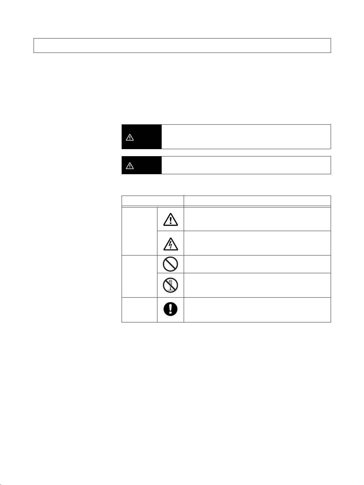
WARNING
Indicates a potentially hazardous situation which, if not avoided,
will result in minor or moderate injury, or may result in serious injury
or death. Additionally there may be significant property damage.
Symbols
CAUTION
Symbol Meaning
Caution
Prohibition
Mandatory
Caution
Indicates a potentially hazardous situation which, if not avoided,
may result in minor or moderate injury or in property damage.
General Caution
Indicates non-specific general cautions, warnings, and
dangers.
Electrical Shock Caution
Indicates possibility of electric shock under specific
conditions.
General Prohibition
Indicates non-specific, general prohibitions.
Disassembly Prohibition
Indicates prohibitions when there is a possibility of injury,
such as from electric shock, as the result of disassembly.
General Caution
Indicates non-specific, general cautions, warnings, and
dangers.
vii
Page 11
Precautions
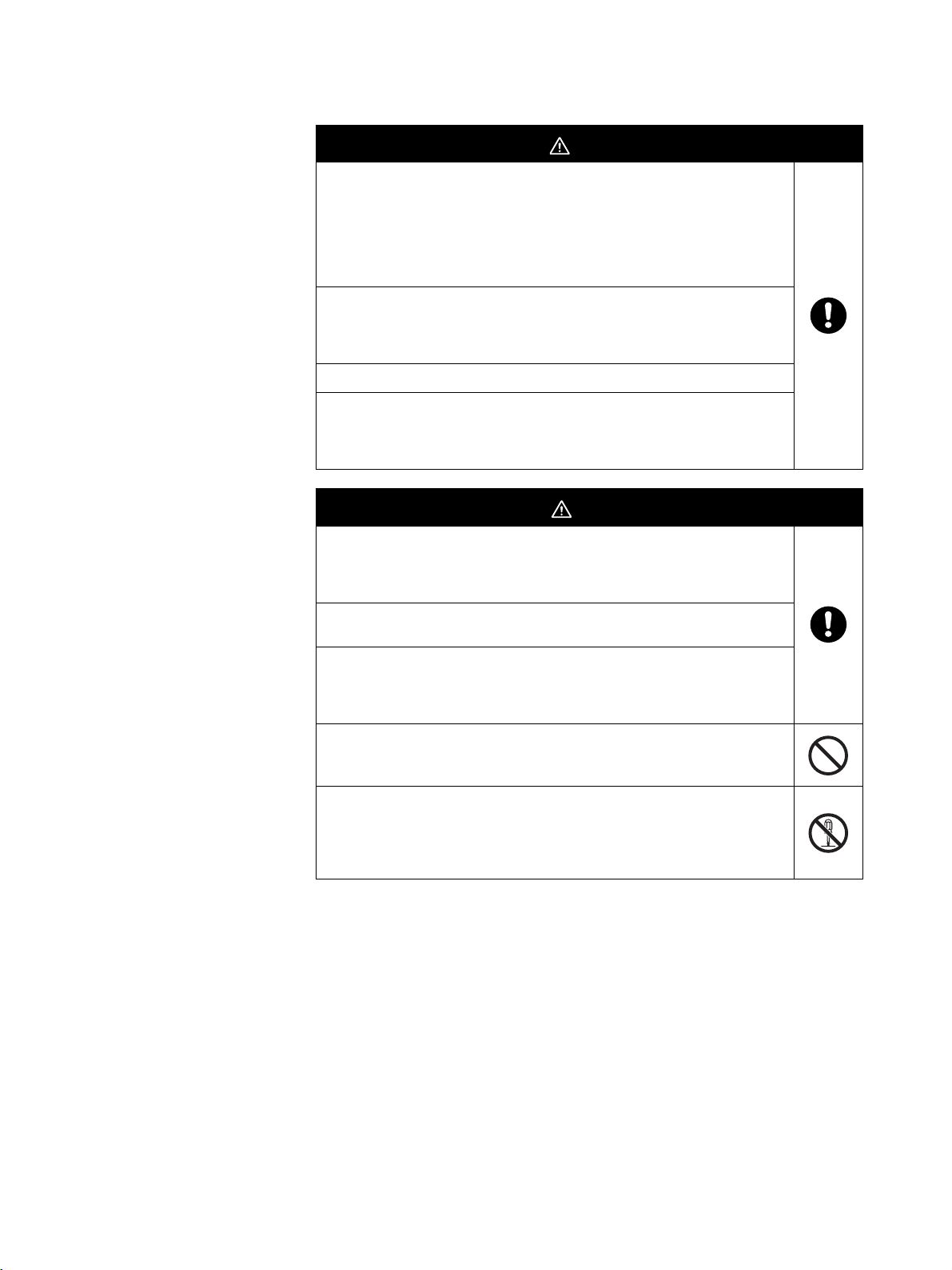
WARNING
Always provide protective circuits in the network. Without protective
circuits, malfunctions may possibly result in accidents that cause serious
injury or significant property damage. Provide double or triple safety
measures in external control circuits, such as emergency stop circuits,
interlock circuits, or limit circuits, to ensure safety in the system if an
abnormality occurs due to malfunction of the product or another external
factor affecting the product's operation.
Design the system to ensure safety in the event of temporary
interruptions in communications due to interference with the
electromagnetic waves used for communications caused by the ambient
environment and application methods.
Do not use this product for real-time control.
Using the FA Wireless SS Terminal near a pacemaker or other medical
device may affect the operation of the medical device, possibly resulting
in serious injury. Never use the FA Wireless SS Terminal near
pacemakers or other medical devices.
CAUTION
Make sure that the direction and polarity (+/−) are correct when
connecting terminal blocks and connectors. Turning ON the power to I/O
circuits with the I/O cables connected in reverse, may result in a blown
output fuse.
Do not apply a voltage or connect a load to the outputs that exceeds the
maximum switching capacity.
Leave the dustproof label attached to the Unit when wiring. Be sure to
remove the label after the completion of wiring, however, to ensure
proper heat dissipation. Removing the label during wiring or leaving the
label attached after wiring may result in fire.
Do not allow pieces of metal, wire clippings, or fine metallic shavings or
filings from installation to enter the product. Doing so may occasionally
result in minor electric shock, fire, or malfunctions.
Do not attempt to disassemble, repair, or modify the product, or touch
the internal parts of the product. Doing so may occasionally result in
minor electric shock, fire, or malfunctions. In Japan, disassembly and
modification is also prohibited under Japan's Radio Law and may be
punishable by law.
viii
Page 12

Precautions for Safe Use
Be sure to observe the following precautions to ensure safe use of the product.
1. Transport the product in the box in which the product was packaged, making sure the product is not subjected to excessive vibrations or shock, or
dropped.
2. Store the product within the specified environment. Allow the product to
warm up to room temperature for at least 3 hours after it has been stored
at
−10°C or lower.
3. Use the product within the specified temperature and humidity ranges.
4. Do not use the product in the following locations.
• Locations subject to extreme temperature changes resulting in condensation
• Locations subject to static electricity, excessive noise, or electric fields
• Locations where the product may come into contact with water, oil, or
chemicals
• Locations where corrosive gases or flammable gases are present
• Locations where large amounts of dust or dirt are present
• Locations subject to spatters, iron chips, or filings
5. Do not install the product outdoors (outside a control panel).
6. Use tape, cord, or other means to hold the product while adjusting the installation position to prevent the product from damage due to falling.
7. Do not install the product in areas where it will be subject to excessive external force, or in walkways.
8. Tighten the mounting screws to the specified torque of 0.5 to 0.6 N·m.
9. Provide sufficient space around the product for heat dissipation.
10. Do not install the product in walkways or locations subject to traffic when
installing the product outside a control panel.
11. Do not reverse the power supply connection or connect the product to an
AC power supply.
12. Use the correct power supply voltage.
13. Use AWG22 to AWG16 to connect wires for post terminals. For solid or
stranded wires, however, use AWG20 to AWG16 (0.52 to 1.5 mm
length of exposed wire is 10 mm.
14. Do not apply voltage to the inputs exceeding the rated voltage range.
15. Use communications cables (RS-232C cables) with a length of 15 m maximum and a load of 2,500 pF maximum.
2
). The
16. Do not lay communications cables (RS-232C cables) and antenna cables
near other high-voltage cables or power lines.
17. Use the specified cables for communications cables (RS-232C cables).
18. Be sure to perform communications tests to confirm operation after wiring
before using the product.
ix
Page 13

19. Always set the product after it is installed or replaced. Set the product correctly according to the manual, and be sure to perform the tests provided
with the product (e.g., communications tests) before operating it.
20. When operating the product without checking serial numbers, check
whether an existing system is present, and design the system carefully to
prevent radio interference.
21. Do not apply excess vibrations or shock to this product. Do not drop this
product.
22. Make sure that wiring and switch settings are correct before starting operations.
23. Other wireless devices operating within the same frequency band may interfere with this product or be adversely affected by this product. Therefore,
be sure to perform the tests provided with the product (e.g., installation
tests) before operating it.
24. Make sure that the antenna is not disconnected during operation.
25. Do not use this product near other devices that may malfunction due to the
electromagnetic waves emitted by this product.
26. Turn OFF the power supply before performing any wiring or replacing devices.
27. Do not touch the product with wet hands.
m
Precautions for Correct Use
Always heed these precautions to prevent faulty operation, malfunction, or
adverse affect on the product's performance and functionality.
1. Communications performance will vary according to the operating environment. Always check operations before using the product.
2. Do not install the antenna in a location surrounded by metal, such as in a
control panel.
3. Install the antenna so that it is as far away as possible from and not parallel
to electric wires or metal plates.
4. Do not use this product in areas exposed to extremely high humidity, near
televisions or radios, near motors or drills that emit sparks, near strong
magnets, or near fluorescent lights.
5. Make sure that the terminal blocks, communications cables (RS-232C cables), and other items with locking devices are properly locked into place.
6. Do not pull or bend cables with force.
7. Do not change the mode selection switch during operation.
28. Dispose of the product as industrial waste.
x
Page 14

m
Package Contents
• WT30 FA Wireless SS Terminal
• Instruction Sheet
• Terminal labels (I/O Slave Stations only)
• Non-slip feet (Serial Master Stations only)
xi
Page 15

Application Guide
Select the required communications configuration and refer to the relevant
pages.
WT30 Basic
Communications
Configuration
The basic configuration uses 8 inputs and 8 outputs, or 16 inputs.
PLC
WT30-M01-FLK
Serial Master station
I/O Slave
station
I/O Slave
station
64 max.
WT30-S@@@
I/O Slave
station
Note Refer to Features . Select from either of two patterns of points for the input/
output terminals of the I/O Slave Station in a system configured using WT30.
A maximum of 16 input terminals per station can be used.
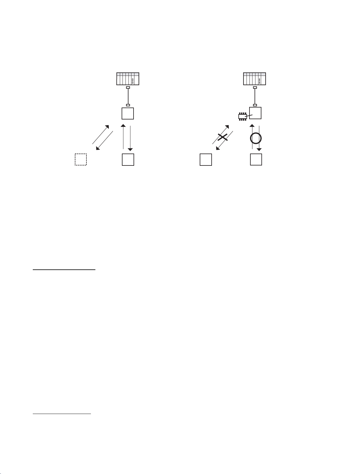
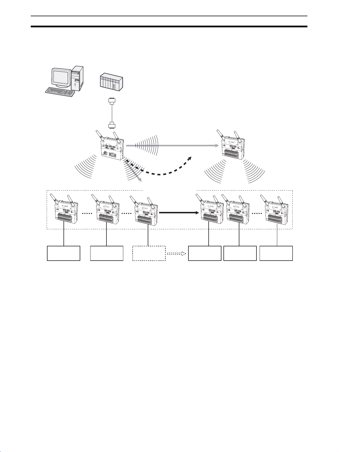
Extending the Communications Distance Using Relay Function
Using Relay Stations
Extending Communications Distance
Switching Communications Path
I/O Slave Station
PLC PLC
WT30-M01-FLK
Serial Master Station
Relay station
(I/O Slave Station)
I/O Slave Station
WT30-S@@@
I/O Slave Station
1. Communications are not possible.
Note Refer to 4-1 Relay Function on page 60. The communications distance can be
extended by using an I/O Slave Station as a Relay Station.
WT30-M01-FLK
Serial Master Station
2. Switch path.
I/O Slave Station
Relay station
(I/O Slave Station)
3. Perform communications
via relay station.
Relocation
WT30-S@@@
I/O Slave Station
xii
Page 16
Communications between WT30 Terminals
Communications with Unregistered Slaves
(No Scan List Registration)
Nodes can be added,
changed, or moved.
I/O Slave Station
No. 2
Communications are performed with
specified I/O Slave Stations on the same
frequency channel within the signal range.
Scan list registration is not required, so I/O
Slave Stations can be added and replaced
using switch settings only. (See note 1.)
Communications with Registered Slaves
(Scan List Registration)
PLC PLC
Serial Master Station
Unregistered
I/O Slave Station
No. 1
I/O Slave Station
No. 2
Communications are performed only with those
I/O Slave Stations within the signal range with
the same frequency channel and that are
registered in the Serial Master Station. Select
whether to register the serial number of the I/O
Slave Station when registering it in the Serial
Master Station. (See note 2.)
Serial Master Station
EEPROM
Registered
I/O Slave Station
No. 1
I/O Slave Station
No. 1 is registered
in EEPROM.
Note 1. Refer to 3-4 Using Unregistered Communications Partners on page 42.
2. Refer to 3-5 Registering the Communications Partner on page 45.
Applied Functions
Communications Error
Output Control
Serial Number Check Perform communications with a specific I/O Slave Station registered in the
Replacing WT30
Terminal s
Installation Methods Refer to page 22.
Available Frequencies Refer to page 105.
I/O Terminal Details Refer to page 28.
Select the status of output terminals if errors occur during wireless communications.
Note Refer to 3-6-6 Output Control for Communications Errors on page 56 under 3-
6 Function Setting Switch.
Serial Master Station including the serial number (the serial number is the
product’s unique number).
Note Refer to 3-6-1 Scan List Registration on page 50 under 3-6 Function Setting
Switch.
Refer to page 73.
Useful Functions
Monitoring All Wireless
Channels Automatically
Refer to page 38.
xiii
Page 17

Manual Outline
Outline of This Manual
Section 1 Introduction
This section explains the features of the WT30 Terminal, including the system configuration and the names and functions
of parts.
Section 2 Hardware Installation and Connection
This section provides information on connection methods and precautions related to installation.
Section 3 Basic Settings
This section describes the procedures for making the WT30 settings and also provides information on the basic system
configuration.
Section 4 Relay Function
This section provides information on the setting methods used to extend the communications distance.
Section 5 Troubleshooting and Maintenance
This section describes error processing, daily inspection, and troubleshooting and maintenance procedures needed to
keep the wireless network operating properly. We recommend reading through the error processing procedures before
operation so that operating errors can be identified and corrected more quickly.
Section 6 CompoWay/F
This section describes the CompoWay/F communications format and the variables that store the ON/OFF data and
received signal strength readings.
Appendices
The appendices provide information on the WT30 specifications and optional accessories. .
xiv
Page 18

TABLE OF CONTENTS
Introduction . . . . . . . . . . . . . . . . . . . . . . . . . . . . . . . . . . . . . . i
Safety Precautions . . . . . . . . . . . . . . . . . . . . . . . . . . . . . . . . . . . . . . . . . . . . . . . . . . . . . . . . vii
Precautions for Safe Use . . . . . . . . . . . . . . . . . . . . . . . . . . . . . . . . . . . . . . . . . . . . . . . . . . . .ix
Precautions for Correct Use . . . . . . . . . . . . . . . . . . . . . . . . . . . . . . . . . . . . . . . . . . . . . . . . . x
Package Contents . . . . . . . . . . . . . . . . . . . . . . . . . . . . . . . . . . . . . . . . . . . . . . . . . . . . . . . . . xi
Application Guide . . . . . . . . . . . . . . . . . . . . . . . . . . . . . . . . . . . . . . . . . . . . . . . . . . . . . . . . . xii
Manual Outline . . . . . . . . . . . . . . . . . . . . . . . . . . . . . . . . . . . . . . . . . . . . . . . . . . . . . . . . . . . xiv
SECTION 1
Introduction. . . . . . . . . . . . . . . . . . . . . . . . . . . . . . . . . . . . . . . 1
1-1 Features . . . . . . . . . . . . . . . . . . . . . . . . . . . . . . . . . . . . . . . . . . . . . . . . . . . . . . . . . . . . . . . . . 2
1-2 Nomenclature and Functions. . . . . . . . . . . . . . . . . . . . . . . . . . . . . . . . . . . . . . . . . . . . . . . . . 6
SECTION 2
Hardware Installation and Connection . . . . . . . . . . . . . . . . 13
2-1 Installation . . . . . . . . . . . . . . . . . . . . . . . . . . . . . . . . . . . . . . . . . . . . . . . . . . . . . . . . . . . . . . . 14
2-2 Connections . . . . . . . . . . . . . . . . . . . . . . . . . . . . . . . . . . . . . . . . . . . . . . . . . . . . . . . . . . . . . . 24
2-3 Wireless System Design Considerations . . . . . . . . . . . . . . . . . . . . . . . . . . . . . . . . . . . . . . . . 32
SECTION 3
Basic Settings. . . . . . . . . . . . . . . . . . . . . . . . . . . . . . . . . . . . . . 35
3-1 Scan List . . . . . . . . . . . . . . . . . . . . . . . . . . . . . . . . . . . . . . . . . . . . . . . . . . . . . . . . . . . . . . . . 36
3-2 Monitoring Unused Frequencies . . . . . . . . . . . . . . . . . . . . . . . . . . . . . . . . . . . . . . . . . . . . . . 37
3-3 Setting Flowchart. . . . . . . . . . . . . . . . . . . . . . . . . . . . . . . . . . . . . . . . . . . . . . . . . . . . . . . . . . 41
3-4 Using Unregistered Communications Partners . . . . . . . . . . . . . . . . . . . . . . . . . . . . . . . . . . . 42
3-5 Registering the Communications Partner . . . . . . . . . . . . . . . . . . . . . . . . . . . . . . . . . . . . . . . 45
3-6 Function Setting Switch. . . . . . . . . . . . . . . . . . . . . . . . . . . . . . . . . . . . . . . . . . . . . . . . . . . . . 50
SECTION 4
Relay Function . . . . . . . . . . . . . . . . . . . . . . . . . . . . . . . . . . . . 59
4-1 Relay Function. . . . . . . . . . . . . . . . . . . . . . . . . . . . . . . . . . . . . . . . . . . . . . . . . . . . . . . . . . . . 60
4-2 Setting Flowchart. . . . . . . . . . . . . . . . . . . . . . . . . . . . . . . . . . . . . . . . . . . . . . . . . . . . . . . . . . 62
4-3 Using Relays . . . . . . . . . . . . . . . . . . . . . . . . . . . . . . . . . . . . . . . . . . . . . . . . . . . . . . . . . . . . . 63
SECTION 5
Troubleshooting and Maintenance . . . . . . . . . . . . . . . . . . . . 67
5-1 Troubleshooting. . . . . . . . . . . . . . . . . . . . . . . . . . . . . . . . . . . . . . . . . . . . . . . . . . . . . . . . . . . 68
5-2 Maintenance and Replacement . . . . . . . . . . . . . . . . . . . . . . . . . . . . . . . . . . . . . . . . . . . . . . . 72
5-3 Replacing WT30 Terminals . . . . . . . . . . . . . . . . . . . . . . . . . . . . . . . . . . . . . . . . . . . . . . . . . . 73
SECTION 6
xv
Page 19

TABLE OF CONTENTS
CompoWay/F . . . . . . . . . . . . . . . . . . . . . . . . . . . . . . . . . . . . . 75
6-1 Frame Structure . . . . . . . . . . . . . . . . . . . . . . . . . . . . . . . . . . . . . . . . . . . . . . . . . . . . . . . . . . . 76
6-2 List of Response Codes . . . . . . . . . . . . . . . . . . . . . . . . . . . . . . . . . . . . . . . . . . . . . . . . . . . . . 78
6-3 Detailed Description of the Services . . . . . . . . . . . . . . . . . . . . . . . . . . . . . . . . . . . . . . . . . . . 78
6-4 Variable Area (Setting Range) List . . . . . . . . . . . . . . . . . . . . . . . . . . . . . . . . . . . . . . . . . . . . 86
6-5 Slave Station Entry Status . . . . . . . . . . . . . . . . . . . . . . . . . . . . . . . . . . . . . . . . . . . . . . . . . . . 88
6-6 Slave Station Input Data . . . . . . . . . . . . . . . . . . . . . . . . . . . . . . . . . . . . . . . . . . . . . . . . . . . . 89
6-7 Slave Station Status . . . . . . . . . . . . . . . . . . . . . . . . . . . . . . . . . . . . . . . . . . . . . . . . . . . . . . . . 90
6-8 Number of Communications Errors. . . . . . . . . . . . . . . . . . . . . . . . . . . . . . . . . . . . . . . . . . . . 91
6-9 Slave Station Route Information . . . . . . . . . . . . . . . . . . . . . . . . . . . . . . . . . . . . . . . . . . . . . . 91
6-10 Slave Station Output Data . . . . . . . . . . . . . . . . . . . . . . . . . . . . . . . . . . . . . . . . . . . . . . . . . . . 92
6-11 Slave Station I/O Size . . . . . . . . . . . . . . . . . . . . . . . . . . . . . . . . . . . . . . . . . . . . . . . . . . . . . . 92
6-12 Serial Number Registration Status. . . . . . . . . . . . . . . . . . . . . . . . . . . . . . . . . . . . . . . . . . . . . 93
6-13 CompoWay/F Communications. . . . . . . . . . . . . . . . . . . . . . . . . . . . . . . . . . . . . . . . . . . . . . . 93
Appendix . . . . . . . . . . . . . . . . . . . . . . . . . . . . . . . . . . . . . . . . . 95
Appendices
Comparison between WT30 and WD30 . . . . . . . . . . 96
A
List of Supported Devices . . . . . . . . . . . . . . . . . . . . . . . . . . . . . . . . . . . . . . . . . . . . . . . . . . . . . . 97
B
I/O Response Time . . . . . . . . . . . . . . . . . . . . . . . . . . . . . . . . . . . . . . . . . . . . . . . . . . . . . . . . . . . . 99
C
Optional Accessories . . . . . . . . . . . . . . . . . . . . . . . . . . . . . . . . . . . . . . . . . . . . . . . . . . . . . . . . . . 101
D
Specifications . . . . . . . . . . . . . . . . . . . . . . . . . . . . . . . . . . . . . . . . . . . . . . . . . . . . . . . . . . . . . . . . 103
E
Frequency Table . . . . . . . . . . . . . . . . . . . . . . . . . . . . . . . . . . . . . . . . . . . . . . . . . . . . . . . . . . . . . . 105
Index. . . . . . . . . . . . . . . . . . . . . . . . . . . . . . . . . . . . . . . . . . . . . 107
Revision History . . . . . . . . . . . . . . . . . . . . . . . . . . . . . . . . . . . 111
xvi
Page 20

SECTION 1
Introduction
This section describes the WT30 Terminal features, communications configuration, and part names and their functions.
1-1 Features . . . . . . . . . . . . . . . . . . . . . . . . . . . . . . . . . . . . . . . . . . . . . . . . . . . . . . 2
1-1-1 Overview. . . . . . . . . . . . . . . . . . . . . . . . . . . . . . . . . . . . . . . . . . . . . . 2
1-1-2 System Configuration . . . . . . . . . . . . . . . . . . . . . . . . . . . . . . . . . . . . 3
1-1-3 Available Models . . . . . . . . . . . . . . . . . . . . . . . . . . . . . . . . . . . . . . . 5
1-2 Nomenclature and Functions . . . . . . . . . . . . . . . . . . . . . . . . . . . . . . . . . . . . . 6
1-2-1 WT30 Terminals: Serial Master Stations . . . . . . . . . . . . . . . . . . . . . 6
1-2-2 WT30 Terminals: I/O Slave Stations . . . . . . . . . . . . . . . . . . . . . . . . 10
1
Page 21

Fe at ur e s Section 1-1
1-1 Features
Information on systems using WT30 FA Wireless SS Terminals (also referred
to as WT30 or WT30 Terminals in this manual) is provided here.
1-1-1 Overview
The WT30 System consists of a Serial Master Station and I/O Slave Stations.
The Serial Master Station is a wireless terminal that collects ON/OFF data
using wireless communications and is connected to a device with an RS232C interface (e.g., a personal computer or PLC). I/O Slave Stations with I/O
terminals can also be connected to a DeviceNet-compatible WD30 Master.
Simple Relay Functions The relay functions enable an increase in the communications area. The
WT30 system supports a maximum of one relay stage using an I/O Slave Station as the Relay Station.
Install Multiple Sets in the
Same Area
Advantage of Full Range
of Channels
Easy Installation and
Settings
I/O Slave Stations with
Built-in I/O
High-level Security
Wireless Communications
Determine Operating
Status from the LED
Display
Path Switching Function Communications will continue via the Relay Station even if communications
Antennas (Optional) Three antenna types are available: Magnet-base Antennas, Flat Antennas,
Changing frequencies removes interference between different sets installed in
the same area. This enables you to construct a wireless system consisting of
up to 10 sets (depending on the installation environment).
Supporting up to 67 channels, you can construct multiple systems without
interference caused by intermodulation.
DIN Rail mounting makes installation easy. The system can be registered simply by setting the switches on the WT30 Terminal, so Support Software is not
required.
I/O Slave Stations are available in three types: With 16 inputs (DC inputs), 8
inputs/8 outputs (DC inputs/transistor outputs), or with different output terminal polarity.
Registering the I/O Slave Station data (serial number and I/O size) in the
Serial Master Station enables communications to be performed with specified
I/O Slave Stations only.
The LED display on the WT30 Terminal can be used to check the WT30's
error status, whether wireless communications are normal, and the received
signal strength.
with the Serial Master Station and I/O Slave Station are unstable, or if the I/O
Slave Station is removed.
and Pencil Antennas.
Compatible with Generalpurpose RS-232C
Interface
Supported in OMRON
Function Block Library for
SYSMAC CS/CJ-series
PLCs
2
A CompoWay/F command must be created to read (write) ON/OFF or other
data. By using the OMRON Function Block Library, PLC users can reduce the
amount of programming required.
The WT30 is supported the OMRON Function Block Library for SYSMAC CS/
CJ-series Programmable Controllers. The I/O Slave Station's input conditions,
output controls, and wireless communications status can be read simply via
the WT30-M01-FLK Serial Master Station connected to the PLC. Using the
OMRON Function Block Library eliminates the need to create communications programs for the WT30, reduces the load on system startup and maintenance, and improves software quality through programming standardization.
For details on the OMRON Function Block Library, refer to the OMRON FB
Library Start-Up Guide (Cat. No. R123).
Page 22

Fe at ur e s Section 1-1
1-1-2 System Configuration
The Serial Master Station is connected to the PLC (Programmable Controller)
or personal computer to perform ON/OFF data communications with the I/O
Slave Stations. The I/O Slave Station can also be used as a Relay Station to
select the path and extend the communications area.
Basic Configuration
Personal computer
PLC
or
RS-232C cable
A
N
T
Serial Master Station
I/O Slave
Stations
1
A
N
T
2
W
T3
0-
M
01
F
L
K
A
N
T
1
A
N
T
2
W
T
3
0
-
S
I
D
1
6
A
N
T
1
A
N
T2
W
T3
0
-
S
I
D
1
6
64 max.
(total number of I/O
Slave Stations)
ON/OFF
data
ON/OFF
data
Device A Device B Device C
A
N
T
1
W
T
3
0
-
S
I
D
1
6
ON/OFF
data
A
N
T
2
3
Page 23
Fe at ur e s Section 1-1
Relay Configuration The communications area can be extended by using a Relay Station, and the
communications path can also be switched when the WT30 Terminals are
moved due to layout changes.
Personal computer
PLC
or
RS-232C cable
The frequency channel is
Serial Master Station
A
N
T1
A
NT2
W
T
3
0
-
S
I
D
1
6
A
N
T1
A
NT
2
WT
3
0
M
0
1
F
L
K
always the same.
Relay station
(3) Perform communications
via the relay station.
(2) Switch the
path.
(1) Communications
are not possible.
64 max.
(total number of I/O
T1
A
N
T
2
W
T
3
0
-
S
I
D
1
6
A
NT
1
W
T
3
0
-
S
I
D
1
6
Relocation
AN
T
2
I/O Slave Station
AN
Slave Stations)
A
N
T1
W
T
3
0
-
S
I
D
1
6
A
N
T1
A
N
T
2
W
T
3
0
-
S
I
D
1
6
AN
T
1
A
NT
2
A
N
T
2
W
T
3
0
-
S
I
D
1
6
A
N
T
1
A
NT
2
W
T
30
-
S
I
D
1
6
ON/OFF data ON/OFF data ON/OFF data ON/OFF data ON/OFF data
Device A Device B Device C Device D Device E Device F
4
Page 24
Fe at ur e s Section 1-1
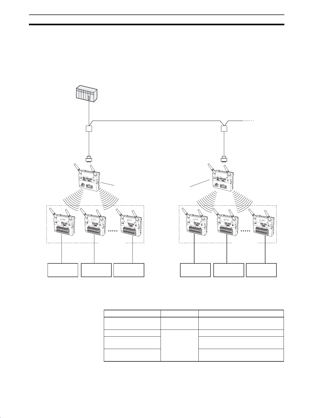
Connecting Multiple Serial
Master Stations
The K3SC RS-232C/RS-485 Interface Converter can be used to configure a
network requiring two or more Serial Master Stations (31 stations max.) or in
environments in which communications are not possible even when Relay
Stations are used in the system. Make sure that the Serial Master Stations are
each allocated unique unit numbers and frequency channels. For details on
wiring cables, refer to the operation manual provided with the K3SC Interface
Converter.
PLC
RS-485 cable
K3SC Interface Converter
RS-232C cable RS-232C cable
A
N
T
Serial Master Station Serial Master Station
I/O Slave
Stations
1
A
N
T
2
W
T
30-
M
01
F
L
K
A different frequency channel is set
for each Serial Master Station.
I/O Slave
Stations
K3SC Interface Converter
A
N
T
1
A
N
T
2
W
T
30
M
01
FL
K
31 max.
A
N
T
1
A
N
W
T
30-
S
I
D
1
6
A
N
T1
T
2
A
N
T
2
W
T
30
-
S
I
D
1
6
A
N
T
1
A
N
T2
W
T
3
0
-
S
I
D
1
6
64 max.
(total number of
I/O Slave Stations)
A
N
T1
A
W
T
30-
S
I
D
1
6
A
N
T
N
T
2
1
A
N
T
2
W
T
3
0
-
S
I
D
1
6
64 max.
(total number of I/O
Slave Stations)
ON/OFF data ON/OFF data ON/OFF data ON/OFF data ON/OFF data ON/OFF data
Device A Device B Device C Device D Device E Device F
1-1-3 Available Models
The following models are available in the WT30 Series according to the polarity (NPN/PNP) of the terminals and number of I/O points.
WT30 Terminal model Type Specifications
WT30-M01-FLK Serial Master
Station
WT30-SID16 I/O Slave StaWT30-SMD16 8 DC inputs (NPN/PNP) + 8 transistor
tions
WT30-SMD16-1 8 DC inputs (NPN/PNP) + 8 transistor
Note The Antenna and Mounting Brackets are not included with the WT30 Termi-
nals.
RS-232C
16 DC inputs (NPN/PNP)
outputs (NPN)
outputs (PNP)
A
N
T1
A
N
T
2
W
T
3
0
-
S
I
D
1
6
5
Page 25
Nomenclature and Functions Section 1-2
1-2 Nomenclature and Functions
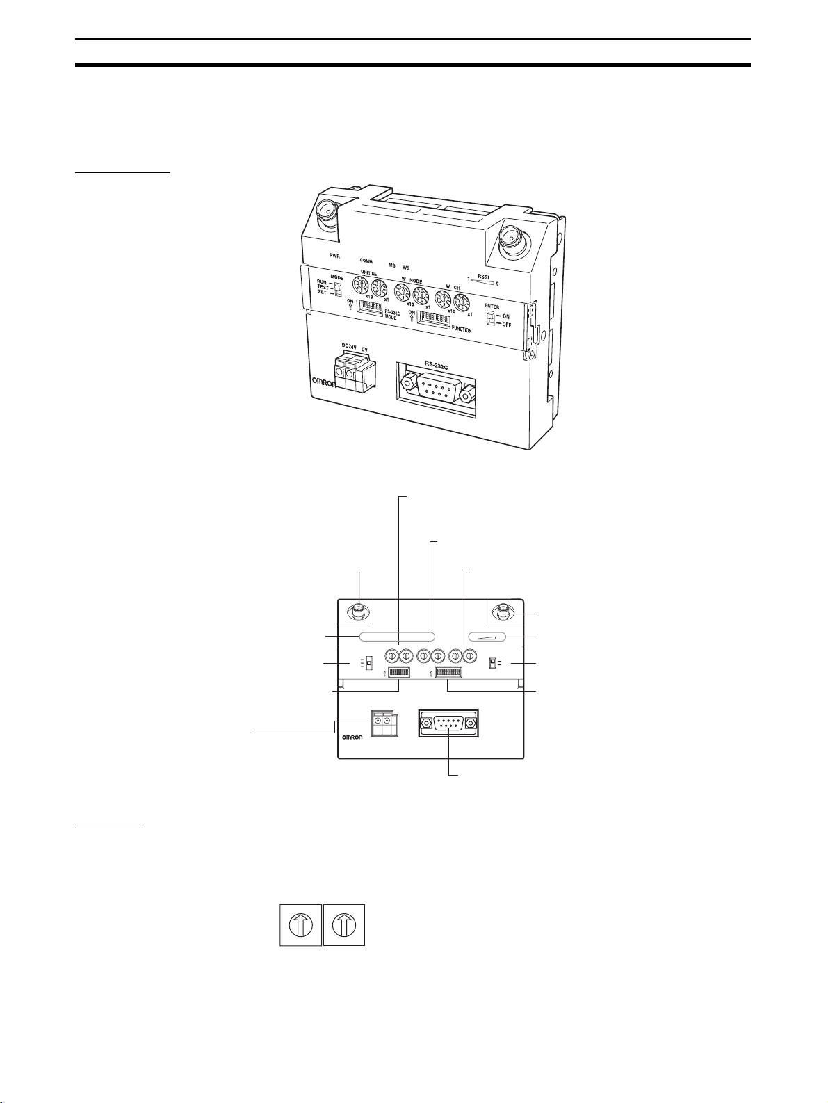
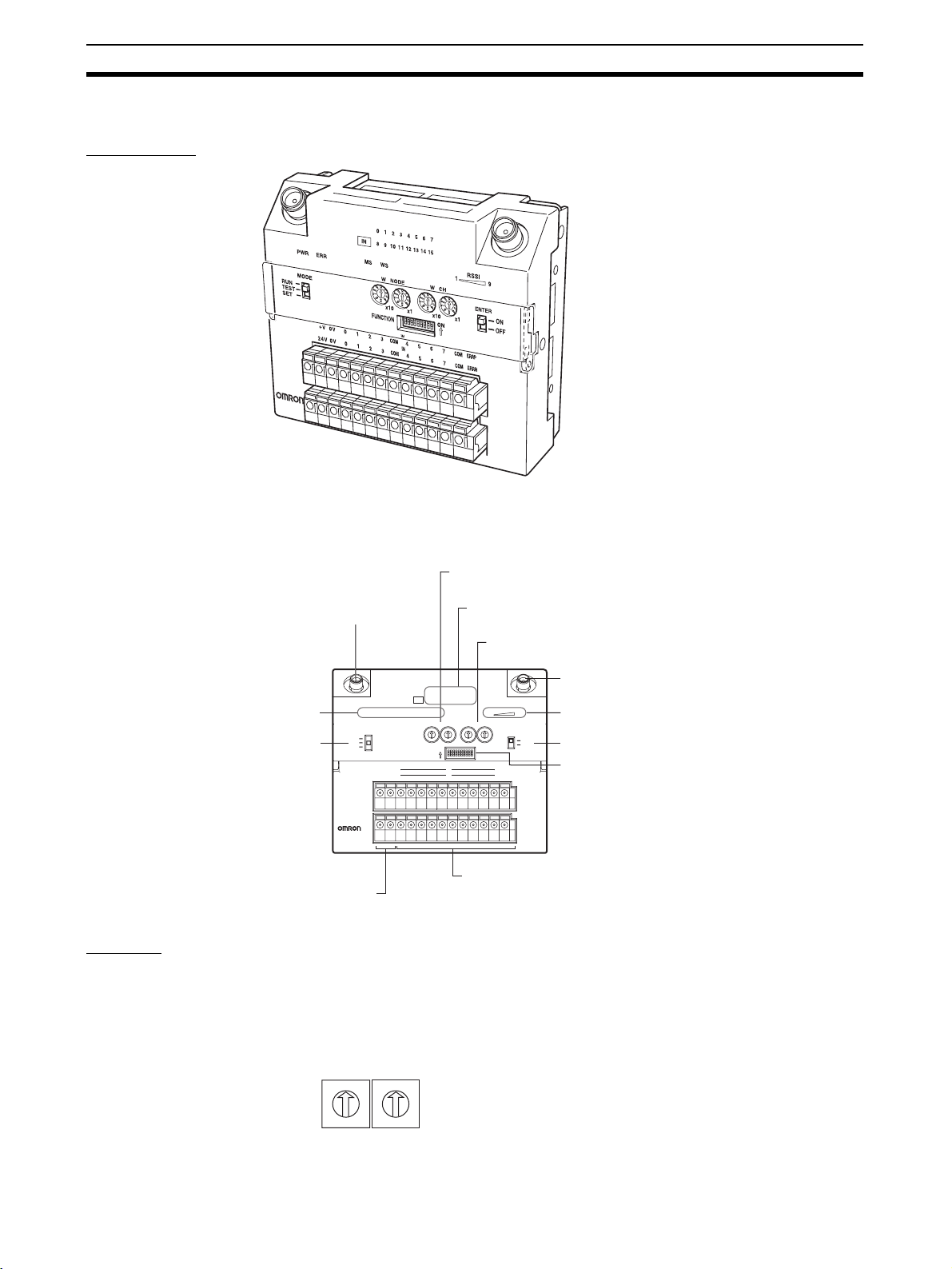
1-2-1 WT30 Terminals: Serial Master Stations
Appearance
ANT1
ANT2
WT30-M01-FLK
Unit No. switch
Set the unit number of the Serial Master Station.
This is used for Host Link communications.
Node setting switch (WNODE)
Antenna terminal (ANT1)
Set the number of connected I/O Slave Stations.
Channel setting switch (WCH)
Set the communications frequency.
Antenna terminal (ANT2)
Status indicators
Mode selection switch
Serial Communications
Setting Switch
Set the baud rate.
Power supply terminal
Supply power to the Unit.
ANT1
PWR
MODE
RUN
TEST
SET
ON
DC24V 0V
WT30-M01-FLK
COMM
MS WS
UNIT No.
W NODE W CH
0
0
0
1
9
2
8
3
7
4
6
5
O
N
123 4 5 6 7
0
1
1
1
9
9
9
2
2
2
8
8
8
3
3
3
7
7
7
4
4
4
6
6
6
5
5
5
x10 x1 x10 x1 x10 x1
8
RS-232C
MODE
O
N
ON
123 4 5 6 7 8 9
RS-232C
0
1
9
8
7
6
5
2
3
4
0
FUNCTION
0
1
9
2
8
3
7
4
6
5
ANT2
RSSI
19
ENTER
ON
OFF
Received signal
strength indicator
Special function switch
Function setting switch
Make the detailed settings
for RUN/TEST/SET mode.
RS-232C terminal
Connect the PLC, personal computer, etc.
Settings
Unit No. Switch Set the unit number for the Serial Master Station. The setting is read when the
power is turned ON. The default is 00.
UNIT No.
9
8
7
X10
0
6
0
1
5
1
9
2
4
2
8
3
3
7
4
6
5
X1
6
Page 26

Nomenclature and Functions Section 1-2
Node Setting Switch
(WNODE)
Set the number of I/O Slave Stations connected to the Serial Master Station.
The setting is read when the power is turned ON. The default is 01.
W NODE
Channel Setting Switch
(WCH)
0
9
8
7
6
X10
Set the communications frequency. The setting is read when the power is
turned ON. For details on frequencies, refer to Appendix F Frequency Table
on page 105. The default is 02.
0
1
5
1
9
2
4
2
8
3
3
7
4
6
5
X1
W CH
0
9
8
7
6
X10
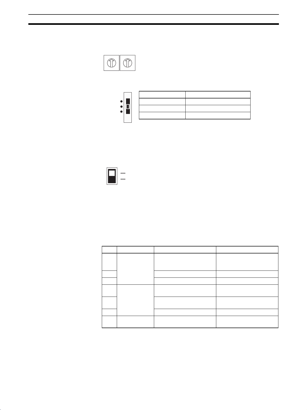
Mode Selection Switch Set the operation mode of the Serial Master Station (three positions).
RUN
TEST
SET
0
1
5
1
9
2
4
2
8
3
Setting range: 01 to 34, 51 to 83
3
7
(The channels 01/51 cannot be used for this product in China.)
4
6
5
X1
Switch setting Operation mode
RUN RUN mode
TEST TEST mode
SET SET mode
By switching the operating mode, a software reset is performed, and the set
value (setting switch setting) is read.
Special Function Switch Use this switch to end operation during scan list registration or as a trigger to
return to the factory settings.
ENTER
ON
OFF
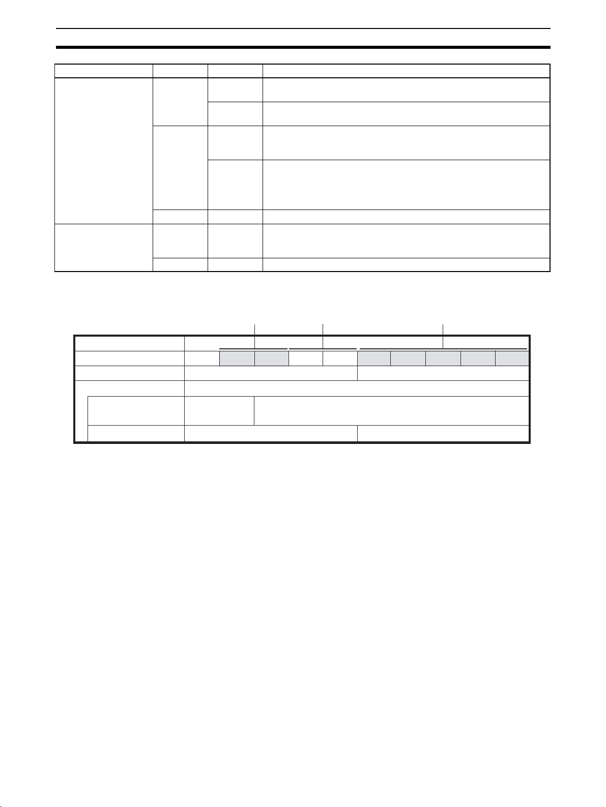
Function Setting Switch Make the detailed settings for RUN/TEST/SET mode.
No. Applicable
mode
1 RUN mode Holds I/O status data when a
2 Enable scan list Disable scan list
3 Relays used Relays not used
4 TEST mode Signal strength monitor dis-
5 All channels automatically
6 --- --7 SET mode Scan list recognition Nothing done
8 Registers specified I/O Slave Registers all I/O Slaves
9 Recognizes serial numbers
10 Not used. --- ---
ON functions OFF functions
Clears I/O status data when
communications error
occurs.
a communications error
occurs.
Signal strength monitor
abled
enabled
Specified channel selected
selected
automatically
Ignores serial numbers
(See note.)
7
Page 27

Nomenclature and Functions Section 1-2
Note The serial number indicates the product’s unique number.
Serial Communications
Setting Switch
Note For example, if pin numbers 2, 3, and 4 are all ON, the total is 7, which corre-
Set the baud rate and other settings.
No. Function ON operation OFF operation
1 Communica-
tions setting
selection
2 Baud rate (bps)
(See note.)
32 0
Tot a l v al u e
44 0
= 0: 1,200
= 1: 2,400
= 2: 4,800
= 3: 9,600
= 4: 19,200
= 5: 38,400
= 6: 57,600
= 7: 115,200
5 Data length 8 bits 7 bits
6 Parity None Yes
7 Odd Even
8 Stop bits 1 bit 2 bits
Detailed settings (settings
for No. 2 to 8 used)
10
Default settings (baud rate:
9,600 bps; data length: 7
bits; parity: even; stop bits:
2) Settings for No. 2 to 8 are
ignored.
sponds to a baud rate of 115,200 bps.
Power Supply Terminal Supplies 24-VDC (allowable voltage range: 20.4 or 26.4 VDC) power to the
WT30 Terminal. The terminal construction uses a screwless terminal block
(Phoenix Contact: FFKDS/V1-5.08 or equivalent).
RS-232C Terminal The serial terminal construction uses D-sub, 9-pin (female) inch screws
(OMRON XM2F-0910-132 or equivalent)
Antenna Terminal Install an Antenna on both the right and left sides. Always use two Antennas.
Display
Status Indicators for Serial Master Station
(1) (2) (3) (4) (5)
RSSI
PWR COMM MS WS
Indicator Color Status Meaning (primary error)
(1) PWR Green Lit Power is being supplied.
Not lit Power is not being supplied.
(2) COMM Yellow Lit Serial communications in progress.
Not lit No serial communications.
(3) MS
(Module Status)
Red Lit A fatal error has occurred that cannot be recovered from, such as a
watchdog timer error, EEPROM, or hardware error.
Replace the WT30 Terminal.
Flashing A non-fatal error, illegal switch settings, or EEPROM checksum error
has occurred that can be recovered from by resetting the system.
Green Lit Communications are normal.
Flashing TEST mode or SET mode has been activated.
--- Not lit Power is not being supplied or the system is resetting.
1
9
8
Page 28
Nomenclature and Functions Section 1-2
Indicator Color Status Meaning (primary error)
(4) WS
(Wireless Status)
(5) RSSI (See note 2.)
(Received Signal
Strength Indicator)
Red Lit A fatal wireless communications error or code sense error has
occurred.
Flashing A non-fatal wireless communications error or verification error (slave
station I/O size mismatch) has occurred, or the slave is not registered.
Green Lit RUN mode: Connection to wireless communications is completed or
remote I/O communications are in progress.
SET mode: Scan list creation completed.
Flashing RUN mode: There is no wireless communications connection or there
are no slaves participating in remote I/O communications.
TEST mode: The received signal strength is being monitored.
SET mode: Scan list is being created.
--- Not lit Wireless communications are not in progress.
Red/yellow/
green
0 to 9 lit Displays the received signal strength in 10 levels. The field strength is
determined by the number of indicators lit: weak for a small number
and strong for a large number.
Green Flashing Special function operation has completed.
Note (1) For details on troubleshooting, refer to 5-1 Troubleshooting on page 68.
(2) The RSSI can be used to confirm the operation status.
Red indicators Yellow indicators Green indicators
Field strength
Number of indicators lit
RUN mode
Test mode
Field strength monitor
test
Installation/confirmation test
Weak Medium Strong
01 23 45 6 7 89
Unstable communications range Stable communications range
Range in which
specified channel
can be used.
Unstable communications range Stable communications range
Range in which specified channel cannot be used.
The received signal strength is indicated using 10 levels. Check the communications status, referring to the field strength level.
9
Page 29
Nomenclature and Functions Section 1-2
pply p
r
1-2-2 WT30 Terminals: I/O Slave Stations
Appearance
ANT1
ANT2
WT30SID16
(WT30-SID16)
Status indicators
Mode selection switch
Settings
Node Setting Switch
(WNODE)
Antenna terminal (ANT1)
ANT1
PWR E RR
MODE
RUN
TEST
SET
WT30SID16
Power supply terminal
Su
ower to the Unit.
Set the node number of the I/O Slave Station (64 max.). The setting is read
when the power is turned ON. After the power is turned ON, any changes to
the switch setting are ignored. The setting for WT30 Terminals used as Relay
Stations is always 99. The default is 01.
Node setting switch (WNODE)
Set the node number of the I/O Slave Station.
I/O terminal status indicators (0 to 7 or 8 to 15)
The contact status is displayed.
0 1 2 3 4 5 6 7
IN
8 9 10 1 1 12 1 3 14 1 5
WS
MS
W NODE W CH
0
0
0
0
1
9
8
7
6
5
O
123 4 5 6 7 8 9
IN
IN
1
1
9
9
2
2
2
8
8
3
3
3
4
4
4
7
7
6
6
5
5
N
0
FUNCTION
1
9
2
8
3
4
7
6
5
x10 x1 x10 x1
ON
V G 0 1 2 3 COM 4 5 67 COM ERRP
0V 8 9 1 0 11 COM 12 13 14 15 COM ERRN
DC24V
I/O terminals
Connect the contact signals.
Channel setting switch (WCH)
Set the communications frequency.
Antenna terminal (ANT2)
ANT2
RSSI
19
ENTER
Received signal strength indicato
ON
Special function switch
OFF
Function setting switch
Make the detailed settings
for RUN/TEST/SET mode.
10
W NODE
0
1
9
2
8
3
7
4
6
5
X10
0
1
9
2
8
3
7
4
6
5
X1
Page 30
Nomenclature and Functions Section 1-2
Channel Setting Switch
(WCH)
Set the communications frequency. For details on frequencies, refer to Appendix F Frequency Table on page 105. The default is 02.
W CH
0
1
9
2
8
7
8
3
4
6
5
X10
Mode Selection Switch Set the operation mode of the Serial Slave Station (three positions).
RUN
TEST
SET
By switching the operating mode, a software reset is performed, and the set
value (setting switch setting) is read.
Special Function Switch Use this switch to clear the recorded signal strength or to return to the factory
settings.
ENTER
Setting range: 01 to 34, 51 to 83
0
1
9
2
(The channels 01/51 cannot be used for this product in China.)
3
7
4
6
5
X1
Switch setting Operation mode
RUN RUN mode
TEST TEST mode
SET SET mode
ON
OFF
Power Supply Terminals Supplies 24-VDC (allowable voltage range: 20.4 or 26.4 VDC) power to the
WT30 Terminal. The terminal construction uses a screwless terminal block
(Phoenix Contact: FFKDS/V1-5.08 or equivalent).
I/O Terminals Connect the I/O contact signals.
Antenna Terminal Install an antenna on both the right and left sides. Always use two antennas.
Function Setting Switch Make the detailed settings for I/O Slave Station operations in RUN mode,
TEST mode, and SET mode.
No. Mode ON functions OFF functions
1 RUN mode Holds I/O status data when a
communications error
occurs.
2 Input hold Normal mode
3 Input filter: 100 ms Input filter: 10 ms
4 TEST mode Signal strength monitor dis-
abled
5 All channels automatically
selected
6 Installation test function Nothing done.
7 to 10Not used. --- ---
Clears I/O status data when
a communications error
occurs.
Signal strength monitor
enabled
Specified channel selected
11
Page 31

Nomenclature and Functions Section 1-2
(3) (4)
Display
Status Indicators for I/O Slave Stations
(1) (2)
0 1 2 3 4 5 6 7
IN
8 9 10 1 1 12 13 14 15
WS
PWR ERR
MS
Indicator Color Status Meaning (primary error)
(1) PWR Green Lit Power is being supplied.
Not lit Power is not being supplied.
(2) ERR Red Lit Error output is ON: Wireless device error, wireless communications
error, or host network error has occurred preventing normal
I/O communications.
Not lit Error output is OFF: Causes of the above conditions have been
removed.
(3) MS
(Module Status)
Red Lit A fatal error has occurred that cannot be recovered from, such as a
watchdog timer error, EEPROM error, or hardware error. Replace the
WT30 Terminal.
Flashing A non-fatal error, illegal switch settings, or EEPROM checksum error
has occurred that can be recovered from by resetting the system.
Green Lit Communications are normal.
Flashing TEST mode or SET mode has been activated.
--- Not lit Power is not being supplied or the system is resetting.
(4) WS
(Wireless Status)
Red Lit A fatal wireless communications error has occurred, or duplicate wire-
less node addresses have been set.
Flashing A non-fatal communications error, disconnection, or communications
timeout has occurred.
Green Lit RUN mode: Connection to wireless communications is completed.
Flashing RUN mode: Wireless communications not connected.
TEST mode: Received signal strength monitoring in progress.
--- Not lit No wireless communications
(5) RSSI (See note 2.)
(Received Signal
Strength Indicator)
Red/yellow/
green
0 to 9 lit Displays the received signal strength in 10 levels. The field strength is
determined by the number of indicators lit: weak for a small number
and strong for a large number.
Green Flashing Special function operation has completed.
(6) 0 to 15 Yellow Lit/not lit Input or output signal ON/OFF status (0 to 7, 8 to 15)
(5)(6)
RSSI
19
Field strength
Number of indicators lit
RUN mode
TEST mode
Field strength monitor
test
Installation/confirmation test
12
Note (1) For details on troubleshooting, refer to 5-1 Troubleshooting on page 68.
(2) The RSSI can be used to confirm the operation status.
Red indicators Yellow indicators Green indicators
Weak Medium Strong
01 23 45 6 7 89
Unstable communications range Stable communications range
Range in which
specified channel
can be used.
Unstable communications range Stable communications range
Range in which specified channel cannot be used.
The received signal strength is indicated using 10 levels. Check the communications status, referring to the field strength level.
Page 32

Hardware Installation and Connection
This section provides information on connection methods and precautions related to installation.
2-1 Installation. . . . . . . . . . . . . . . . . . . . . . . . . . . . . . . . . . . . . . . . . . . . . . . . . . . . 14
2-1-1 Installation location . . . . . . . . . . . . . . . . . . . . . . . . . . . . . . . . . . . . . 14
2-1-2 Installation Precautions. . . . . . . . . . . . . . . . . . . . . . . . . . . . . . . . . . . 14
2-1-3 Determining the Antenna Installation Position. . . . . . . . . . . . . . . . . 14
2-1-4 Flat Diversity Antennas . . . . . . . . . . . . . . . . . . . . . . . . . . . . . . . . . . 18
2-1-5 Dimensions . . . . . . . . . . . . . . . . . . . . . . . . . . . . . . . . . . . . . . . . . . . . 19
2-1-6 Installation . . . . . . . . . . . . . . . . . . . . . . . . . . . . . . . . . . . . . . . . . . . . 22
2-2 Connections. . . . . . . . . . . . . . . . . . . . . . . . . . . . . . . . . . . . . . . . . . . . . . . . . . . 24
2-2-1 Cable Connections . . . . . . . . . . . . . . . . . . . . . . . . . . . . . . . . . . . . . . 24
2-2-2 Wiring Precautions . . . . . . . . . . . . . . . . . . . . . . . . . . . . . . . . . . . . . . 26
2-2-3 WT30 Power Supply Wiring . . . . . . . . . . . . . . . . . . . . . . . . . . . . . . 27
2-2-4 I/O Terminal Wiring . . . . . . . . . . . . . . . . . . . . . . . . . . . . . . . . . . . . . 28
2-3 Wireless System Design Considerations. . . . . . . . . . . . . . . . . . . . . . . . . . . . . 32
2-3-1 Construction of Multiple Wireless Systems . . . . . . . . . . . . . . . . . . . 32
2-3-2 Communications Errors Caused by Intermodulation . . . . . . . . . . . . 33
2-3-3 Serial Master Station Input/Output Data . . . . . . . . . . . . . . . . . . . . . 33
SECTION 2
13
Page 33

Installation Section 2-1
2-1 Installation
Make sure that the radio wave conditions at the installation site are favorable
before actually installing the WT30 Terminals.
2-1-1 Installation location
Do not install this device in locations such as the following:
• Areas exposed to direct sunlight
• Areas with extremely high humidity
• Near devices such as televisions, radios, and computers
• Near devices that emit sparks, such as motors, drills, and welding equipment
• Near strong magnets
• Near fluorescent lights
• Inside metal panels or locations surrounded by metal or concrete
If the WT30 Terminal is installed in a metal panel, be sure to mount the entire
Antenna outside the panel where there are no interfering objects.
2-1-2 Installation Precautions
• Install the Antennas for the Serial Master Station and I/O Slave Stations
or the Relay Stations and I/O Slave Stations in parallel.
• Install the Antennas as far away as possible from and not parallel to electric wires or metal panels.
• Use wood screws when installing the WT30 on a wooden surface.
• Use M4 screws for installation if the provided installation screws are not
used.
• Communications are not possible if the Terminals is too close to each
other (within 1 m). Make sure that sufficient distance is provided between
WT30 Terminals.
2-1-3 Determining the Antenna Installation Position
The WT30 uses radio waves with a frequency of 2.4 GHz, which is very high.
High-frequency waves exhibit strong rectilinear propagation and are reflected
easily. For this reason, careful consideration of the Antenna installation position is required to achieve optimum wireless performance.
1,2,3... 1. If possible, install Antennas so that there is a direct line of sight between
them.
High-frequency waves, which exhibit strong rectilinear propagation, are
used and so it is difficult for the waves to reach areas that are not in a direct
line of sight, as shown in the following diagram. This is a particularly important point for communications at long distances (e.g., exceeding 50 m or
60 m.)
14
Transmitting
Antenna
Area not in a direct line of
sight from the Antenna
Obstacle
Antenna that is
difficult for the waves
to reach
Antenna that
waves will reach
Page 34

Installation Section 2-1
If the Antennas are installed in locations with relatively high ceilings and a
lot of open space, even if there is no direct line of sight between the Antennas, if one of the Antennas is installed in a high location, communications
may still be possible via radio waves that are reflected off the ceiling.
2. Install in as high a location as possible.
As mentioned in the preceding paragraph, if the Antennas are installed in
high locations, because the space surrounding the Antennas will be more
open, there will be less influence from obstacles, and the radio waves will
propagate more easily.
High Antenna
Radio wave energy
Obstacle
3. Do not place obstacles (especially metal objects) near the Antennas.
If there are obstacles near the Antennas (in particular, in the direction of
radio wave propagation), the radio waves may not be propagated due to
the influence of the objects. Metal objects have the greatest influence as
they reflect radio waves, whereas glass and plastic objects allow the waves
to pass through and so have the least influence. Be sure to install Antennas at least 30 cm away from any obstacles.
4. Cable Loss in Magnet-base Antennas
Loss occurs in the cable when using WT30-AT001 Magnet-base Antennas.
Therefore, the maximum communications distance is approximately 50 m
indoors, which is shorter than for Pencil Antennas.
5. Cable Bending Radius
The minimum bending radius for WT30-AT001 Magnet-base Antennas is
38 mm. Also, do not bend the cable at points less than 34 mm from the end
connected to the WT30 Terminal or at points less than 40 mm from the end
connected to the Antenna.
The minimum bending radius for WT30-AT002 Flat Diversity Antennas is
50 mm. Also, do not bend the cable at points less than 23 mm from the end
connected to the WT30 Terminal or at points less than 20 mm from the end
connected to the Antenna.
Cable Bending Radius and Dimensions
34
R38
40
WT30-AT001
Magnet-base Antenna
23
WT30-AT002
Flat Diversity Antenna
R50
(Unit: mm)
20
15
Page 35

Installation Section 2-1
6. Separate different sets of Antennas as much as possible.
If different sets of Antennas are close to each other, they will influence
each other and thereby influence wireless communications, causing an increase in the number of retries, and a reduction in the possible communications distance. Separate different sets of Antennas by at least 2 m if
possible.
7. Do not install the two Magnet-base Antennas close to each other.
If the two Antennas are close to each other, the diversity effect will not be
utilized. Magnet-mounting allows the positions to be adjusted easily. If possible, separate the Antennas by an even greater distance.
8. Install the Antennas with the same orientation.
Install Antennas that are performing communications with the same orientation, as shown in the following diagram. Install Flat Diversity Antennas in
the same way. If they are installed at an angle of 90
sible communications distance will be shortened.
° to each other, the pos-
9. Separate the Antennas from ID Tags by at least 3 m.
The OMRON V690 Microwave RFID System uses frequencies within the
range used by the WT30 Terminals. Therefore, if the two systems are used
on the same floor, observe the following points when installing the systems.
• Separate the Antennas and ID Tags by at least 3 m.
• Set the frequency to a channel other than channels 12 to 30 or channels 62 to 79.
10. Direction of Waves Emitted from Magnet-base Antennas
Antennas emit waves in certain directions, and there are certain directions
in which waves are received easily. These directions are known as the “directional characteristics.” The directional characteristics for Pencil Antennas and Magnet-base Antennas when they are installed vertically are
donut-shaped, spreading outwards horizontally. Radio waves are emitted
in every horizontal direction but are not emitted upwards or downwards.
Radio wave emissions from the tip of the Antenna are low, so the communications distance will be shortened if the tips of the Antennas for both the
WT30 Terminals are installed facing each other.
16
Page 36

Installation Section 2-1
(
Radio Wave Emission Pattern
(Actual Measurements)
270˚
Side View
240˚
210˚
300˚
330˚
Overhead View
180˚
150˚
120˚
Antenna
Area that waves will reach
90˚
60˚
-40-50-60
2.45 GHz
30˚
-30
0˚
11. Other Points about Magnet-base Antennas
• The magnet on the Magnet-base Antenna is very strong. Do not remove the Antenna by pulling on the cover or cable. Doing so may damage the Antenna. Always hold the base when handling the Antenna.
• Twist the cable as little as possible.
• Design the hole for passing the cable through so that the cable is protected.
12. Direction of Waves Emitted from Flat Diversity Antennas
Flat Diversity Antennas also have directional characteristics, in the same
way as Magnet-base Antennas.
270˚
240˚
300˚
Direction of Radio Wave Emissions
Visualization)
210˚
180˚
150˚
120˚
90˚
2.45 GHz
Radio Wave Emission Pattern
(Actual Measurements)
60˚
330˚
0˚
-40-50-60
-30
30˚
17
Page 37

Installation Section 2-1
t
13. Do not subject the Antenna to shock.
Do not install the Antenna in a location in which it may be hit by other objects. If installation in such a location is required, take sufficient measures
to protect the Antenna. Subjecting the Antenna to strong shock may cause
either external or internal damage to the Antenna. Internal damage that is
not necessarily externally visible may prevent communications, such as
broken wires.
2-1-4 Flat Diversity Antennas
Secure the Flat Diversity Antenna to the Mounting Bracket with screws. The
Mounting Bracket includes a magnet for attachment to metal surfaces. Do not
tighten the vertical and horizontal angle adjustment knobs at first to allow
adjustment of the Antenna position and angle. After adjusting to the correct
position, tighten the knobs securely.
M3 screws
Magnet
Adjustment knob for vertical angle
WT30-FT011 Flat Diversity Antenna Mounting Bracket
Vertical angle
Horizontal angle
Magne
Adjustment knob for
horizontal angle
18
Page 38

Installation Section 2-1
g
g
2-1-5 Dimensions
WT30 FA Wireless SS Terminals
Serial Master Station
(Unit: mm)
105
8.1 40 8.9
I/O Slave Station
(Example: WT30-SID16)
90
7.3
90
ANT1
PWR
MODE
RUN
TEST
SET
ON
WT30-M01-FLK
ANT1
PWR ERR
MODE
RUN
TEST
SET
VG0123
DC24V
WS
MS
COMM
UNIT No.
W NODE W CH
0
0
0
0
1
2
3
9
4
8
5
7
6
x10 x1 x10 x1 x10 x1
O
N
123 4 5 6 7
1
1
1
2
2
2
3
3
9
9
9
4
4
4
8
8
8
5
5
5
7
7
7
6
6
6
O
N
ON
RS-232C
123 4 5 6 7 8 9
8
MODE
105
0 1 2 3 4 5 6 7
IN
8 9 10 11 12 13 14 15
WS
MS
W NODE W CH
0
0
1
1
9
9
2
2
8
8
3
3
4
4
7
7
6
6
5
5
x10 x1 x10 x1
O
N
ON
123 4 5 6 7 8 9
IN
COM
4567
0V 8 9 10 11
IN
COM
12 13 14 15
3
0
1
2
9
8
5
7
6
0
1
9
2
8
3
4
7
6
5
0
19
0
1
2
3
3
9
4
4
8
5
7
6
0
FUNCTION
19
0
1
9
2
8
3
4
7
6
5
FUNCTION
COM ERRP
COM
ANT2
RSSI
ENTER
ON
OFF
WT30-FT001 or WT30-FT002
DIN Rail Mountin
ANT2
RSSI
ENTER
ON
OFF
ERRN
Bracket
(Unit: mm)
8.1 40 8.9
7.3
WT30SID16
WT30-FT001 or WT30-FT002
DIN Rail Mountin
Bracket
19
Page 39

Installation Section 2-1
With Antenna Installed
(Same for Serial Master Station and Slave I/O Stations)
Cable Bending Angle and Dimensions
150
85
8.1
40
(Unit: mm)
8.9
34
R38
40
WT30-AT001
Magnet-base Antenna
23
R50
20
WT30-AT002
Flat Diversity Antenna
WT30-AT003
Pencil Antenna
WT30-FT001 or WT30-FT002
DIN Rail Mounting Bracket
Magnet-base Antenna Flat Diversity Antenna
WT30-AT001
(Unit: mm)
WT30-AT002
26
57.5
(Unit: mm)
Three, 3 dia.
115
94
20
35.8 dia.
39
13.3
2010
10.5 dia.
57.5
52
10.5 dia.
2010
20
Page 40

Installation Section 2-1
Pencil Antenna
WT30-AT003
(Unit: mm)
75
5
12 dia.
Flat Diversity Antenna Mounting Bracket
WT30-FT011
(Unit: mm)
33
58
Magnet
32
15 15
60.5 36
21
Page 41

Installation Section 2-1
2-1-6 Installation
The WT30 Terminal can be installed either by standing it on a table top, fixing
it with screws, or mounting it to a DIN Rail. When fixing with screws, mount
the WT30 Terminal to the L-shaped Surface Mounting Bracket before mounting to a panel or other surface.
Table-top Mounting Attach the adhesive non-slip feet to the bottom of the Serial Master Station
and stand the Serial Master Station on a flat surface.
Adhesive non-slip feet
Using an L-shaped
Holes are required for mounting with L-shaped Brackets.
Bracket
Mounting Hole Dimensions (Unit: mm)
M4
40
120
Surface Mounting Bracket
Mounting Hole Dimensions (Unit: mm)
M4
Mounting hole
ANT1
ANT2
WT30-M01-FLK
Surface Mounting Bracket
Serial Master Station
Mounting hole
22
A
N
T
1
A
N
T
2
40
WT30-
120
Surface Mounting Bracket
SID16
Surface Mounting Bracket
I/O Slave Station
Tighten the WT30 mounting screws using the specified torque of 0.5 to
0.6 N·m.
Page 42

Installation Section 2-1
Using a DIN Rail Do not install the WT30 in a metal panel when using a Pencil Antenna. Doing
so will decrease the wireless performance significantly. To install the WT30 in
a panel, use either a Magnet-base Antenna or Flat Antenna and install the
Antenna on the outside of the panel. Refer to Appendix D Optional Accesso-
ries on page 101.
Insert spring
A
(1) Insert the end of section
A into the base of the
Adapter.
Suitable
DIN Rails
Two types of suitable DIN Rail are available. Both have a width of 35 mm. The
height is either 7.5 mm or 15 mm (conform to DIN, EN, IEC, and JIS C2812
standards).
Model DIN Rail Specifications
WT30-FT001 TH35-7.5 Rail width: 35 mm, Height: 7.5 mm
WT30-FT002 TH35-15 Rail width: 35 mm, Height: 15 mm
Mounting the
(3) Position the Adapter on
the WT30 and secure
with screws.
DIN Rail Adapter
DIN Rail Dimensions (Unit: mm)
No burrs
Part A
35±0.3
0.3 max.
TH35-7.5
Part A Detail
0
7.5
-0.4
TH35-15
Part A Detail
1±0.04
1±0.04
15
15˚
(2) Pull section A to the right
and lower while
compressing the spring.
Mounting Method
Tighten the WT30 mounting screws
using the specified torque of 0.5 to
0.6 N·m.
Hook the top of the
(1)
WT30 over the DIN Rail.
DIN Rail
(2)
27
Dust-proof Label
Remove the dust-proof
label after mounting.
24
ANT1
W
T
3
0
M
ANT2
0
1
F
L
K
23
Page 43

Connections Section 2-2
Removal Method
ANT1
COMM
PWR
8
MODE
7
6
RUN
TEST
SET
ON
DC24V 0V
WT30-M01-FLK
Insert a flat-blade screwdriver
or other tool into the lower
hook and pull down.
2-2 Connections
2-2-1 Cable Connections
WT30 (Serial Master
Station)
Connect the Serial Master Station to the PLC or personal computer using RS232C cable. If the WT30 is installed in a location subject to frequent vibration,
secure the RS-232C cable close to the connector so that force will not be
applied to the connector.
ANT1
PWR
MODE
RUN
TEST
SET
WT30-M01-FLK
MS WS
UNIT No.
W NODE W CH
0
0
0
0
0
9
9
9
9
9
1
1
1
1
1
8
8
8
8
2
2
2
2
2
7
7
7
7
7
3
3
3
3
3
6
6
6
6
4
4
4
4
4
5
5
5
5
5
x10 x1 x10 x1 x10 x1
O
N
O
N
ON
RS-232C
123 4 5 6 7 8 9
123 4 5 6 7
0
8
FUNCTION
MODE
RS-232C
COMM
MS WS
UNIT No.
0
0
1
1
9
9
2
2
8
8
3
3
7
7
4
4
6
6
5
5
x10 x1 x10 x1 x10 x1
O
N
ON
RS-232C
123 4 5 6 7
8
MODE
DC24V 0V
ANT2
RSSI
19
0
9
1
8
2
ENTER
3
6
4
5
ON
OFF
W NODE W CH
0
0
1
1
9
9
2
2
8
8
3
7
7
4
4
6
6
5
5
O
N
ON
123 4 5 6 7 8 9
RS-232C
Unhook the WT30
(2)
from the DIN Rail.
DIN Rail
Pull the bottom side
(1)
forwards.
54321
ANT2
RSSI
19
0
0
1
1
9
9
2
2
8
8
3
ENTER
3
3
7
7
4
4
6
6
5
5
ON
0
OFF
FUNCTION
9876
D-sub, 9-pin Female End at WT30
Pin No.
Signal
---
RD
SD
---
SG
---
---
---
---
I/O direction
---
Output
Input
---
---
---
---
---
---
1
2
3
4
5
6
7
8
9
24
RS-232C cable
Connected to PLC or
personal computer
Page 44

Connections Section 2-2
Serial Connection Example 1
The serial setting for the personal computer is set to no flow control.
Personal computer
D-sub, 9-pin, Female End
Signal Pin No.
CD 1
RD 2
SD 3
ER 4
SG 5
DR 6
RS 7
CS 8
RI 9
RS-232C
cable
D-sub, 9-pin, Male End
Signal Pin No.
1
RD 2
SD 3
4
SG 5
6
7
8
9
A
N
T
1
W
T
3
0
M
0
1
F
L
K
WT30
The connections indicated by dotted lines are used with the
recommended cables, but are not a problem for operation.
Recommended Cables
Model Cable length
XW2Z-0100U-3 1 m
XW2Z-0200U-3 2 m
XW2Z-0500U-3 5 m
Serial Connection Example 2
If the serial setting for the personal computer cannot be set to no flow control,
prepare the cables short-circuiting pins 4 and 6, and pins 7 and 8.
A
N
T
2
Personal computer
D-sub, 9-pin, Female End
Signal Pin No.
CD 1
RD 2
SD 3
ER 4
SG 5
DR 6
RS 7
CS 8
RI 9
RS-232C
cable
D-sub, 9-pin, Male End
Signal Pin No.
ޓ 1
RD 2
SD 3
ޓ 4
SG 5
ޓ 6
ޓ 7
ޓ 8
ޓ 9
A
N
T
1
W
T
3
0
M
0
1
F
L
K
WT30
A
N
T
2
25
Page 45

Connections Section 2-2
p
Serial Connection Example 3
The serial setting for the OMRON PLC is set to no flow control.
PLC
D-sub, 9-pin, Female End
Signal Pin No.
1
SD 2
RD 3
RS 4
CS 5
6
7
8
SG 9
RS-232C
cable
D-sub, 9-pin, Male End
Signal Pin No.
1
RD 2
SD 3
4
SG 5
6
7
8
9
A
N
T
1
W
T
3
0
M
0
1
-F
L
K
WT30
The connections indicated by dotted lines are used with the
recommended cables, but are not a
roblem for operation.
Recommended Cables
Model Cable length
XW2Z-0200U-5 2 m
XW2Z-0500U-5 5 m
When connecting to CS/CJ-series set the communications ports on the PLC
side as shown in the following table.
Communications Settings: User Settings (User-specified Settings)
Item name Set value Connecting to a WT30 with
initial settings
Serial communications mode
Parameters
Data length
Stop bits
Parity
Baud rate Matches the communications
Send delay time Sets a user-specified time
CTS control Sets a user-specified time
Response timeout
monitoring time
Serial Gateway Serial Gateway
Matches the communications
settings of the WT30 Terminal.
Data length: 7 bits
Stop bits: 2
Parity: Even
9,600 bit/s
settings of the WT30 Terminal.
Same
(Default: None)
Note: The communications
port of the CPU Unit cannot
be set.
Same
(Default: None)
Note: The communications
port of the CPU Unit cannot
be set.
Sets a user-specified time
Same
(Default: 5 s)
A
N
T
2
2-2-2 Wiring Precautions
• Wire the signal lines separately from power lines to prevent noise interference.
• Do not lay wiring close to the Antenna.
• Turn OFF the power before performing any wiring.
26
Page 46

Connections Section 2-2
• Wire the terminals using the following post terminals and cables.
Length of exposed wire Cable (AWG22 to AWG16)
single/stranded wire (0.32 to 1.5 mm
2
)
Use a tool of the appropriate size to crimp the post terminal. Make an incision
in the cable and remove the covering so that the cable is either the same
length as or approximately 0.5 mm longer than the post terminal, as shown in
the following diagram. Make sure that no stray wires are protruding and the
post terminal is not damaged.
10 mm
Correct Example
Incorrect Example
Stray wire
0 to 0.5 mm
Surface damage
Insufficient length
removed
Manufactured by Phoenix Contact
Post terminal
AWG22 AI 0.34-12
AWG20 AI 0.5-10
AWG18 AI 0.75-10,
AI 1-10
AWG16 AI 1.5-10
Crimping tool
CRIMPFOX ZA3
Insert a screwdriver into the screwless terminal block as shown in the following diagram, and keeping the screwdriver inserted, insert the post terminal.
Use the same procedure to remove the post terminal. Secure the wiring close
to the connector to prevent direct force from being applied to the wiring due to
twisted cables or the weight of the cables.
Dust-proof Label Remove the dust-proof label after completing wiring.
A
N
T
Attaching Terminal Labels
(I/O Slave Stations Only)
1
W
T
3
0
-
M
0
1
-
F
L
K
Attach terminal labels inside the switch cover to the positions shown in the following diagram.
ANT1
PWR ERR
MODE
RUN
TEST
SET
A
N
T2
0 1 2 3 4 5 6 7
IN
8 9 10 11 12 13 14 15
WS
MS
W NODE W CH
0
1
9
2
8
3
7
4
6
5
x10 x1 x10 x1
ON
9
8
7
0
1
6
5
O
2
3
4
N
123 4 5 6 7 8 9
0
1
9
2
8
3
7
4
6
5
0
RSSI
19
0
1
9
2
8
3
7
4
6
5
FUNCTION
ENTER
ANT2
ON
OFF
2-2-3 WT30 Power Supply Wiring
The power supply voltage for WT30 Terminals is 24 VDC.
27
Page 47

Connections Section 2-2
Error output power supply
DC24V
Power supply voltage 24 VDC
Allowable voltage range 20.4 to 26.4 VDC
WT30 Terminals require a 24-VDC power supply. Provide a power supply of at
least 15 W, considering the inrush current generated at startup. An OMRON
Switching Power Supply Unit is recommended. Refer to Appendix B List of
Supported Devices on page 97 for details.
2-2-4 I/O Terminal Wiring
WT30-SID16 Input Unit
VG 0 1 2 3
0V
0123
Inputs
COM
4567
COM COM
45 67
InputsPower supply
COM ERRP
ERRN
Input Characteristics
Error Output Characteristics
Item Specifications
Input voltage 24 VDC
Allowable voltage range 20.4 to 26.4 VDC
Input impedance 4.7 kΩ (typical)
Input current 5 mA (typical)
ON voltage/current character-
17.4 VDC, 3.0 mA min.
istics
OFF voltage/current charac-
5.0 VDC, 1.0 mA max.
teristics
Input filter 10 ms/100 ms (Selected using switch.)
Item Specifications
Input voltage 24 VDC
Allowable voltage range 20.4 to 26.4 VDC
Max. switching current 100 mA max. per output (at 20.4 to 26.4 VDC)
Simultaneous usage of error output NPN/PNP is not
possible.
Leakage current 0.1 mA max.
Residual voltage 1.0 V max.
Fuse One for every two outputs except for error output cir-
cuits, which have one for every NPN/PNP output. (No
fuses can be replaced by the user.)
28
Page 48

Connections Section 2-2
p
)
y
Input Circuit Diagram
Error output power supply
VG 0 1 2 3
0V
DC24V
0123
Power suppl
Inputs
COM
4567
COM COM
45 67
In
uts
WT30-SMD16(-1) I/O Slave Stations
Output/Error Output Characteristics
Input voltage 24 VDC
Allowable voltage range 20.4 to 26.4 VDC
Max. switching current 100 mA max. per output (at 20.4 to 26.4 VDC)
Leakage current 0.1 mA max.
Residual voltage 1.0 V max.
Fuse One for every two outputs except for error output cir-
Error output (PNP)
COM ERRP
Secondary internal circuit
ERRN
Error output (NPN
Item Specifications
Simultaneous usage of error output NPN/PNP is not
possible.
cuits, which have one for every NPN/PNP output. (No
fuses can be replaced by the user.)
IN 0
IN 1
IN 2
IN 15
COM (IN)
Error output/output power supply
V0
G
Error output/output power supply
V0
G
Error output/output power supply Inputs Error output (PNP)
VG 0 1 2 3
0V
DC24V
0123
COM
4567
COM COM
45 67
COM ERRP
ERRN
Power supply Outputs Error output (NPN)
With WT30-SMD16 NPN outputs, the output COM terminal (lower level) is internally connected to the V terminal. When the error output ERRN terminal is
used, the COM terminal on the output side can be shared. The polarity of PNP
outputs is opposite from that of the error output ERRP terminal, and therefore
the common cannot be shared.
With WT30-SMD16-1 PNP outputs, the output COM terminal (lower level) is internally connected to the G terminal. When the error output ERRP terminal is
used, the COM terminal on the output side can be shared. The polarity of NPN
outputs is opposite from that of the error output ERRN terminal, and therefore
the common cannot be shared.
29
Page 49

Connections Section 2-2
NPN Output Circuit Diagram PNP Output Circuit Diagram
Fuse
Fuse
Fuse
Secondary internal circuit
Fuse
Error Output Circuit Diagram
V
Fuse
ERRP
V
OUT 0
OUT 1
OUT 2
OUT 7
G
Secondary internal circuit
Fuse
V
OUT 0
OUT 1
OUT 2
OUT 3
OUT 7
G
Connecting to Input
Devices
Fuse
ERRN
Secondary internal circuit
G
Input Device with Contact Output
WT30
INOutput
COM
Internal circuits
Input Device with NPN Open-collector Output
WT30
Internal circuits
+
Output
0 V
Sensor
power
supply
IN
COM
30
Page 50

Connections Section 2-2
Input Device with Voltage Output
Sensor
power supply
+
Output
Sensor circuits
0 V
Input Device with NPN Output
+
Internal circuits
0 V
Input Device with PNP Output
Sensor
power
supply
Sensor circuits
+
Output
0 V
WT30
IN
COM
WT30
INOutput
COM
WT30
IN
COM
Connecting to Output
Loads
PNP Output
Load
NPN Output
Load
WT30
V
OUT (P)
G
COM
WT30
COM
V
OUT (N)
G
31
Page 51

Wireless System Design Considerations Section 2-3
Connecting to Error
Output
PNP Output
Load
WT30
V
ERRP
G
NPN Output
WT30
V
Load
ERRN
G
2-3 Wireless System Design Considerations
2-3-1 Construction of Multiple Wireless Systems
When constructing a system for using multiple Serial Master Stations, the following points must be considered. Consult your OMRON representative.
Setting Wireless Channels Frequencies that are not interfered with by radio waves must be selected for
the wireless channels. (Radio interference can be handled by retry processes
between the wireless networks, but will lengthen the system response time.)
The WT30 supports 67 wireless channels from which to select. As a rough
guide, however, a maximum of 10 wireless systems can be used in a single
area without radio interference on account of the following considerations.
1,2,3... 1. Do not select neighboring wireless channels as they have a large amount
of interference.
2. Due to the fundamental nature of radio waves, if two or more waves with
different frequencies are output at exactly the same time, mutual interference will occur between the different frequencies, and new waves will be
generated with frequencies at intervals equal to the intervals between the
output frequencies. (This phenomenon is called intermodulation.)
For example, if channels 5 and 9 are used, electromagnetic interference
will be generated with channels 1 and 13, as shown in the following diagram. In this case, channels 2 and 14 can be used, but the frequency of
channel 51 is located between the frequencies for channels 1 and 2, and
the frequency of channel 63 is located between the frequencies for channels 13 and 14. Therefore, the channel with the frequency following channel 1 is channel 51. Channels 5, 9, 51, and 63 can be used without
interference. For details on frequencies, refer to Appendix F Frequency Ta-
ble on page 105.
32
Page 52

Wireless System Design Considerations Section 2-3
y
f
1 - (f2 - f1) = Channel 1
Radio wave created
by intermodulation
Serial Master
Station
I/O Slave Station
Channel 51
f1 = Channel 5 f2 = Channel 9
Serial Master
Station
I/O Slave Station
Channel 63
f
2 + (f2 - f1) = Channel 13
Radio wave created
by intermodulation
Do not select the frequencies of radio waves created by intermodulation.
Antenna Separation
Distance
The distance between WT30 Terminals has a large influence on the amount
of interference received. In particular, there may often be cases where Serial
Master Stations are installed relatively closely to each other. Separate the
Antennas for different Serial Master Stations by at least 2 m if possible.
Test Confirmation Perform a test to see whether or not the WT30 Terminals are receiving inter-
ference. Use the RSSI (Received Signal Strength Indicator) on both the Serial
Master Station and I/O Slave Station to check the interference.
Frequenc
2-3-2 Communications Errors Caused by Intermodulation
Communications errors and retry processing may occur due to intermodulation resulting in transmission delays. To eliminate the influence of intermodulation, do not set the wireless channels for WT30 Terminals in every system to
frequencies at regular intervals.
2-3-3 Serial Master Station Input/Output Data
The Serial Master Station’s input/output data is cleared by turning OFF the
power. After turning ON the power, an output signal of all zeros (OFF) is sent
to the output of the I/O Slave Stations from the Serial Master Station.
(1) At power OFF:
All I/O data cleared.
Serial Master
Station
A
N
T
1
W
T
3
0
-
A
N
T
2
M
0
1
F
L
K
(2) AT power ON:
Sends all "0" output signal.
I/O Slave
Station
A
N
T
1
W
T
3
0
-
S
ID
1
6
A
N
T
2
(3) Output signal: All "0"
Intermodulation
Due to the fundamental nature of radio waves, if two or more waves with different frequencies
are output at exactly the same time, mutual interference will occur between the different
frequencies, and new waves will be generated with frequencies at intervals equal to the intervals
between the output frequencies.
33
Page 53

Wireless System Design Considerations Section 2-3
34
Page 54

SECTION 3
Basic Settings
This section describes the procedures for making the WT30 settings and also provides information on the function settings.
3-1 Scan List . . . . . . . . . . . . . . . . . . . . . . . . . . . . . . . . . . . . . . . . . . . . . . . . . . . . . 36
3-2 Monitoring Unused Frequencies. . . . . . . . . . . . . . . . . . . . . . . . . . . . . . . . . . . 37
3-2-1 Wireless Channel Monitor for Specified Channels . . . . . . . . . . . . . 37
3-2-2 Monitoring All Wireless Channels . . . . . . . . . . . . . . . . . . . . . . . . . . 38
3-2-3 Clearing the Recorded Peak Values for the Received Signal Strength 40
3-3 Setting Flowchart . . . . . . . . . . . . . . . . . . . . . . . . . . . . . . . . . . . . . . . . . . . . . . 41
3-4 Using Unregistered Communications Partners . . . . . . . . . . . . . . . . . . . . . . . . 42
3-4-1 Finding Unused Channels. . . . . . . . . . . . . . . . . . . . . . . . . . . . . . . . . 42
3-4-2 Operation Settings . . . . . . . . . . . . . . . . . . . . . . . . . . . . . . . . . . . . . . 43
3-4-3 Confirming Connection Status . . . . . . . . . . . . . . . . . . . . . . . . . . . . . 44
3-5 Registering the Communications Partner . . . . . . . . . . . . . . . . . . . . . . . . . . . . 45
3-5-1 Finding Unused Channels. . . . . . . . . . . . . . . . . . . . . . . . . . . . . . . . . 46
3-5-2 Registering Communications Partners (All I/O Slave Stations). . . . 47
3-5-3 Operation Settings . . . . . . . . . . . . . . . . . . . . . . . . . . . . . . . . . . . . . . 49
3-5-4 Confirming Connection Status . . . . . . . . . . . . . . . . . . . . . . . . . . . . . 49
3-6 Function Setting Switch . . . . . . . . . . . . . . . . . . . . . . . . . . . . . . . . . . . . . . . . . 50
3-6-1 Scan List Registration. . . . . . . . . . . . . . . . . . . . . . . . . . . . . . . . . . . . 50
3-6-2 Stopping Registration of All I/O Slave Stations . . . . . . . . . . . . . . . . 51
3-6-3 Scan List Enabled/Disabled Mode . . . . . . . . . . . . . . . . . . . . . . . . . . 52
3-6-4 Input Hold. . . . . . . . . . . . . . . . . . . . . . . . . . . . . . . . . . . . . . . . . . . . . 53
3-6-5 Input Filter . . . . . . . . . . . . . . . . . . . . . . . . . . . . . . . . . . . . . . . . . . . . 55
3-6-6 Output Control for Communications Errors. . . . . . . . . . . . . . . . . . . 56
3-6-7 Returning to Default Settings . . . . . . . . . . . . . . . . . . . . . . . . . . . . . . 56
35
Page 55

Scan List Section 3-1
3-1 Scan List
Communications are divided into two types depending on whether the communications partner (I/O Slave Station) is registered or unregistered. Registration of communications partners is referred to as scan list registration. The
mode for communications with specified, registered communications partners
is referred to as scan list enabled mode. The mode for communications
between the Serial Master Station and unregistered I/O Slave Stations from
the specified node number 1 up to the specified number of nodes is referred
to as scan list disabled mode.
For details, refer to 3-6-1 Scan List Registration on page 50.
• Communications with Unregistered
Communications Partner
(Scan List Disabled Mode)
Add or replace WT30 Terminals easily
WT30
I/O Slave Station
Node No. 2
Mistaken recognition will occur if an I/O
Slave Station set with the same node
number or frequency channel is present
in the radio signal range.
Immediate operation is possible by simply
setting the frequency channel and node
number for the I/O Slave Station after it is
added or replaced. This usage is supported provided that the same frequency
channel is not already being used nearby,
and that the operation on a different frequency channel can be confirmed.
• Communications with Registered
Communications Partner
(Scan List Enabled Mode)
PLC PLC
No. 1
EEPROM
Not registered Registered
WT30
I/O Slave Station
Node No. 1
Unregistered Slaves Registered Slaves
WT30
I/O Slave Station
Node No. 2
Communications are performed with registered I/O Slave Stations only. Therefore,
mistaken recognition will not occur. Communications are also only performed with
the specified I/O Slave Stations, thereby
eliminating unnecessary polling and
heightening security.
By registering the I/O Slave Station with
the serial number check enabled, re-registration at the Serial Master Station is
required when an I/O Slave Station is
replaced.
WT30 Serial Master StationWT30 Serial Master Station
WT30
I/O Slave Station
Node No. 1
36
For details on using unregistered slave stations, refer to 3-4 Using Unregistered Communications Partners and for using registered slave stations, refer
to 3-5 Registering the Communications Partner.
Page 56

Monitoring Unused Frequencies Section 3-2
3-2 Monitoring Unused Frequencies
The peak value of the received signal strength in the frequency band being
used is monitored onsite, enabling selection of available channels (frequencies).
3-2-1 Wireless Channel Monitor for Specified Channels
The actual received signal strength for the channel specified using the channel setting switch can be monitored in realtime using the display.
1,2,3... 1. Before turning ON the power, set the function setting switch as follows:
ON
1
3
7
5
2
6
4
Bit 4: OFF (field strength monitor enabled)
Bit 5: OFF (specified channel)
9
0
8
2. Set the frequency channel to be monitored using the channel setting
switch (WCH switch).
W CH
0
1
9
8
7
9
2
8
3
7
4
6
5
X10
3. Set the mode setting switch to TEST mode, and turn ON the power. The
MS and WS indicators will flash green.
RUN
Setting range: 01 to 34, 51 to 83
0
1
2
3
4
6
5
X1
MS: Module status indicator
WS: Wireless status indicator
TEST
SET
4. The monitoring results are displayed using the 10 levels of the RSSI (received signal strength indicator).
WSMS
Number of LEDs lit:
Field strength: Weak
Few
Many
Strong
5. The received signal strength is indicated using 10 levels according to the
Received Signal Strength Indicator
Field strength
Number of indicators lit
RUN mode
TEST mode
Field strength monitor
test
Installation/confirmation test
Weak Medium Strong
01 23 45 6 7 89
Unstable communications range Stable communications range
Range in which
specified channel
can be used.
Unstable communications range Stable communications range
The received signal strength is indicated using 10 levels. Check the communications status, referring to the field strength level.
frequency monitoring results obtained by setting the channel setting
switch. The monitoring results are not recorded in the EEPROM.
Red indicators Yellow indicators Green indicators
Range in which specified channel cannot be used.
37
Page 57

Monitoring Unused Frequencies Section 3-2
3-2-2 Monitoring All Wireless Channels
The received signal strength for all wireless channels is automatically
scanned (the channel is changed every second), and the peak value is automatically recorded in EEPROM. (All channels are level 0 in the default settings.) The recorded peak value can be read during automatic scanning or
when automatic scanning is stopped. Approximately 70 seconds is required to
read the received signal strength for all channels. The automatic scan status
can be confirmed using the WS indicator. In the first cycle, the WS indicator
flashes green, and from the second and subsequent cycles, the WS indicator
is lit green.
When starting the automatic scan to perform monitoring for the first time,
allow a minimum of approximately 70 seconds before reading the peak values.
During automatic scanning, data is constantly overwritten. Therefore, to read
data collected onsite from an office, for example, the data must be read when
automatic scanning is stopped.
Note To change the installation position of the WT30 Terminal if the surrounding
radio wave conditions change, the recorded peak values for the received signal strength must be cleared to enable an accurate reading of the surrounding
radio wave conditions. Clear the recorded data and then start a new automatic scan.
1,2,3... 1. Before turning ON the power, set the function setting switch as follows:
ON
1
3
7
5
2
6
4
8
Bit 4: OFF (field strength monitor enabled)
Bit 5: ON (automatically select all channels)
9
0
2. Change the mode setting switch setting to TEST mode and turn ON the
power. The MS/WS indicators will flash green.
MS: Module status indicator
WS: Wireless status indicator
WSMS
The automatic scan will start for all channels. The automatic scan will start
from the specified channel, proceed sequentially up to channel 83, and
then return to channel 1. Scanning will continue until the power is turned
OFF (for the total 67 channels).
RUN
TEST
SET
38
Page 58

Monitoring Unused Frequencies Section 3-2
g
g
3. The WS indicator will change from flashing green to being lit green when
the automatic scan completes one cycle (the received signal strength is recorded). Automatic scanning will continue.
Lit greenFlashing green
WS WS
Automatic scanning executes a single scan for each channel. Radio waves
may be received from channels for which the automatic scan has been
completed. Therefore, executing the automatic scan for longer periods of
time, and not for just a single cycle, is recommended.
4. Specify the channel to be monitored using the channel setting switch.
Reading the Recorded
Received Signal Strength
after Stopping the
Automatic Scan
1,2,3... 1. Set the function setting switch as shown below and change the setting of
W CH
0
1
9
8
7
9
2
8
3
7
4
6
6
5
X10
5. The peak value for the recorded received signal strength is displayed using
the 10 levels indicated by the RSSI.
This operation is used to monitor the peak value after first stopping the automatic scan temporarily so that the recorded received signal strength peak values will not be overwritten.
the mode setting switch from RUN mode to TEST mode. The MS indicator
will flash green.
ON
3
1
2
7
5
6
4
Setting range: 01 to 34, 51 to 83
0
1
2
3
4
5
X1
Bit 4: ON (field strength monitor disabled)
9
8
0
MS: Module status indicator
Number of LEDs lit:
Field stren
th: Weak
Few
Many
Strong
MS
2. Set the frequency channel to be monitored using the channel setting
switch.
W CH
0
1
9
8
7
9
2
8
3
7
4
6
6
5
X10
3. The peak value for the recorded received signal strength is displayed using
the 10 levels indicated by the RSSI.
Setting range: 01 to 34, 51 to 83
0
1
2
3
4
5
X1
Number of LEDs lit:
Field stren
th: Weak
Few
Many
Strong
39
Page 59

Monitoring Unused Frequencies Section 3-2
3-2-3 Clearing the Recorded Peak Values for the Received Signal
Strength
Use the following procedure to clear the peak values recorded for all the channels.
1,2,3... 1. Set the function setting switch as follows:
ON
Bit 4: ON (field strength monitor disabled)
3
1
2
4
9
7
5
6
0
8
2. Change the setting for the mode setting switch from RUN mode to TEST
mode.
RUN
TEST
SET
3. Change the setting of the special function switch as follows:
ENTER
ON
OFF
4. Confirm that data has been cleared using the RSSI. The RSSI’s green indicators will flash 4 or 5 times to indicate that data has been cleared.
OFF → ON → OFF
RSSI display: Green indicators flashing
40
Page 60

Setting Flowchart Section 3-3
3-3 Setting Flowchart
The setup procedure for the WT30 is described below. To perform simple
communications without registering I/O Slave Stations, perform the following
settings omitting step 2.
1
Monitor received signal
strength to find unused
frequency.
Using unregistered
communications partner
The WT30-TOOLS can also be used.
2
Register
communications partner.
2
(1) I/O Slave Station settings
· Set node number.
· Set frequency channel.
(2) Serial Master Station settings
· Set node number.
· Set frequency channel.
3
Make operation settings.Make operation settings.
4
Check communications
status.
Common Settings for Serial Master
and I/O Slave Stations
· Set frequency channel.
· Check RSSI level.
(1) I/O Slave Station settings
· Set node number.
· Set frequency channel.
(2) Serial Master Station settings
· Set node number
(i.e., number of nodes in network).
· Set frequency channel.
· WS indicator lit green.
· RSSI flashing green.
Serial Master Station settings
· Enable/disable scan list
Confirmation at I/O Slave Station
· Check that MS and WS indicators
are lit green.
· Check RSSI level.
Confirmation at Serial Master Station
· Check that MS and WS indicators
are lit green.
· Set the node number.
· Check RSSI level.
Check the installation location's
electromagnetic wave status and find
an unused frequency. Confirm using
the RSSI on the Serial Master
Station or I/O Slave Station.
Register the I/O Slave Stations in the
Serial Master Station.
Execute scan list registration to
register the I/O Slave Station data
(serial number and I/O size) in the
Serial Master Station. Set the number
of Stations to register using the Serial
Master Station's node number setting.
Make each of the settings using the
function setting switch.
When the Serial Master Station's scan
list is enabled, communications are
performed with the specified I/O Slave
Stations registered in step 2.
When the scan list is disabled,
communications are performed with
the number of I/O slave Stations set
on the Serial Master Station's node
number switch. For example, if node
number 3 is set, communications are
performed iwth I/O Slave Stations 1 to
3.
Check whether communications are
normal using the RSSI and WS (wireless network status) indicators on the
Serial Master Station or I/O Slave Stations.
WT30 Utility
WT30-TOOLS
The WT30 utility called WT30-TOOLS can be downloaded free of charge from the OMRON
website. Be sure to read the software licence agreement before downloading the utility.
41
Page 61

Using Unregistered Communications Partners Section 3-4
g
3-4 Using Unregistered Communications Partners
Use the following procedure to operate a system configured with a Serial
Master Station and either a PLC or personal computer connected via RS232C in which the I/O Slave Stations have not been registered.
3-4-1 Finding Unused Channels
Specify the frequency channel using the channel setting switch and monitor
the actual measurement values for the received signal strength in real time.
Common Settings for Serial Master Station and I/O Slave Stations
1,2,3... 1. Before turning ON the power, set the function setting switch as follows:
ON
3
1
2
7
5
6
4
2. Change the setting for the mode setting switch to TEST mode, and then
turn ON the power.
RUN
TEST
SET
Bit 4: OFF (field strength monitor enabled)
Bit 5: OFF (specified channel)
9
8
0
3. Specify the channel to be monitored using the channel setting switch.
Note For details on monitoring wireless channels when all wireless channels are
specified, refer to 3-2-2 Monitoring All Wireless Channels on page 38.
4. Check the monitoring results on the RSSI display indicated using 10 levels.
Received Signal Strength Indicator
Field strength
Number of indicators lit
RUN mode
TEST mode
Field strength monitor
test
Installation/confirmation test
Weak Medium Strong
01 23 45 6 7 89
Unstable communications range Stable communications range
Range in which
specified channel
can be used.
Unstable communications range Stable communications range
W CH
0
1
9
8
7
9
2
8
3
7
4
6
5
X10
In the RSSI shown in the following table, if one or less indicator is lit, the
corresponding channel being monitored can be used.
Red indicators Yellow indicators Green indicators
Setting range: 01 to 34, 51 to 83
0
1
2
3
4
6
5
X1
Range in which specified channel cannot be used.
Number of LEDs lit:
Field stren
th: Weak
Few
Many
Strong
42
The received signal strength is indicated using 10 levels. Check the communications status, referring to the field strength level.
Page 62

Using Unregistered Communications Partners Section 3-4
r
4
3-4-2 Operation Settings
I/O Slave Station Settings
1,2,3... 1. Before turning ON the power, set the function setting switch as required.
ON
3
1
2
7
5
6
4
8
2. Set the node number of the I/O Slave Station using the node setting switch.
Bit 1: Hold/clear I/O data if communications errors occu
Bit 2: Input hold/normal mode
Bit 3: Input filter (100 ms/10 ms)
9
0
Serial Master Station Settings
1,2,3... 1. Before turning ON the power set the function setting switch as required.
W NODE
0
1
9
2
8
8
3
7
7
4
6
5
X10
3. Set the same frequency channel used by the Serial Master Station using
the channel setting switch.
0
1
9
2
3
4
6
5
X1
Setting range: 01 to 64
W CH
0
1
9
8
7
9
2
8
3
7
4
6
5
X10
4. Change the setting for the mode setting switch to RUN mode, and then turn
ON the power.
Setting range: 01 to 34, 51 to 83
0
1
2
3
4
6
5
X1
RUN
TEST
SET
ON
1
3
7
5
2
6
4
Bit 1: Hold/clear I/O data if communications errors occur
Bit 2: OFF (scan list disabled)
9
0
8
Note When the scan list is disabled, communications are performed with the num-
ber of I/O Slave Stations set using the node setting switch.
Example 1: If the node setting switch is set to 2, communications will be performed with up to 02 I/O Slave Stations.
Example 2: If the node setting switch is set to 64, communications will be performed with up to 64 I/O Slave Stations.
2. Set the number of I/O Slave Stations to be connected using the node setting switch.
Polling will be performed for the number of I/O Slave Stations set here. For
example, if the number is set to 2, communications will be performed with
only 2 Stations even if 3 or more Stations actually exist.
W NODE
0
9
8
7
6
0
1
9
2
8
3
7
4
6
5
X10
1
5
X1
2
3
4
Setting range: 01 to 6
43
Page 63

Using Unregistered Communications Partners Section 3-4
g
3. Set the frequency channel using the channel setting switch.
W CH
0
1
9
2
8
8
3
7
7
4
6
5
X10
4. Change the setting for the mode setting switch to RUN mode, and then turn
ON the power.
Setting range: 01 to 34, 51 to 83
0
1
9
2
3
4
6
5
X1
RUN
TEST
SET
3-4-3 Confirming Connection Status
Confirm the communications status between the I/O Slave Stations and Serial
Master Station using the RSSI (received signal strength indicator) display. To
confirm the status from the Serial Master Station, specify the I/O Slave Station
to be monitored using the node setting switch. Be sure to turn ON the power
to the I/O Slave Station in RUN mode before the Serial Master Station.
I/O Slave Stations
1,2,3... 1. Confirm that the mode setting switch on the I/O Slave Station is set to RUN
mode.
Serial Master Station
RUN
TEST
SET
2. Confirm that the MS and WS indicators on the I/O Slave Station are lit
green.
MS: Module status indicator
WS: Wireless status indicator
WSMS
3. Check the strength of the received signal from the Serial Master Station indicated using 10 levels on the RSSI display.
Many
Number of LEDs lit:
Field stren
th: Weak
Few
Strong
1,2,3... 1. Confirm that the mode setting switch on the Serial Master Station is set to
RUN mode.
RUN
TEST
SET
44
Page 64

Registering the Communications Partner Section 3-5
4
g
2. Confirm that the MS and WS indicators on the Serial Master Station are lit
green.
MS: Module status indicator
WS: Wireless status indicator
WSMS
3. Specify the node number of the I/O Slave Station to be monitored on the
Serial Master Station’s node setting switch.
W NODE
0
9
8
7
6
X10
Note The Serial Master Station node number is set to the maximum
4. Check the strength of the received signal from the I/O Slave Station specified by the node setting switch. The strength is indicated using 10 levels
on the RSSI display.
0
1
5
1
9
2
8
3
7
4
2
3
4
6
5
Setting range: 01 to 6
X1
number of I/O Slave Stations. When the maximum number of
nodes is set to a number higher that the number of nodes connected, however, the highest node number is not used. The communications partner for this node number does not exist, so no display
is shown on the RSSI. If the node number is changed to that of a
node that is actually connected, the RSSI display will indicate the
corresponding signal strength.
Many
Number of LEDs lit:
Field stren
th: Weak
Few
Strong
Received Signal Strength Indicator
Red indicators Yellow indicators Green indicators
Field strength
Number of indicators lit
RUN mode
TESTmode
Field strength monitor
test
Installation/confirmation test
Weak Medium Strong
01 23 45 6 7 89
Unstable communications range Stable communications range
Range in which
specified channel
can be used.
Unstable communications range Stable communications range
Range in which specified channel cannot be used.
The received signal strength is indicated using 10 levels. Check the communications status, referring to the field strength level.
3-5 Registering the Communications Partner
Use the following procedure to operate a system configured with a Serial
Master Station and either a PLC or personal computer connected via RS232C in which the I/O Slave Stations have been registered.
45
Page 65

Registering the Communications Partner Section 3-5
g
3-5-1 Finding Unused Channels
Specify the frequency channel using the channel setting switch and monitor
the actual measurement values for the received signal strength in real time.
Common Settings for the Serial Master Station and I/O Slave Stations
1,2,3... 1. Before turning ON the power, set the function setting switch as follows:
ON
3
1
2
7
5
6
4
2. Change the setting for the mode setting switch to TEST mode, and then
turn ON the power.
RUN
TEST
SET
3. Specify the channel to be monitored using the channel setting switch.
W CH
9
8
7
X10
0
6
0
1
9
2
8
3
7
4
6
5
Bit 4: OFF (field strength monitor enabled)
Bit 5: OFF (specified channel)
9
0
8
Setting range: 01 to 34, 51 to 83
1
2
3
4
5
X1
Note For details on monitoring wireless channels when all wireless channels are
specified, refer to 3-2-2 Monitoring All Wireless Channels on page 38.
4. Check the monitoring results on the RSSI display indicated using 10 levels.
Received Signal Strength Indicator
Field strength
Number of indicators lit
RUN mode
TEST mode
Field strength monitor
test
Installation/confirmation test
Weak Medium Strong
01 23 45 6 7 89
Unstable communications range Stable communications range
Range in which
specified channel
can be used.
Unstable communications range Stable communications range
The received signal strength is indicated using 10 levels. Check the communications status, referring to the field strength level.
Many
Number of LEDs lit:
Field stren
th: Weak
Few
Strong
In the RSSI shown in the following table, if one or less indicator is lit, the
corresponding channel being monitored can be used.
Red indicators Yellow indicators Green indicators
Range in which specified channel cannot be used.
46
Page 66

Registering the Communications Partner Section 3-5
3
3-5-2 Registering Communications Partners (All I/O Slave Stations)
Register I/O Slave Stations at the Serial Master Station. The Serial Master
Station performs wireless communications only with those I/O Slave Stations
that are registered. This prevents unwanted I/O Slave Stations from joining
the network. When registering, the serial number check can also be enabled
or disabled. Serial number recognition is the function that writes the I/O Slave
Station’s unique number to the Serial Master Station.
Scan List Registration
with Serial Number Check
Note When the serial number check is not required, turn OFF bit 9 of the Serial
I/O Slave Station Settings
1,2,3... 1. Before turning ON the power, set the function setting switch as required.
The serial number is registered at the same time as the corresponding I/O
Slave Station. This function has the advantage of preventing mistaken Slave
recognition even if a WT30 Terminal with the same channel (frequency), same
node number, and same model is in the radio signal range. The disadvantage
is that I/O Slave Stations that are replaced must be re-registered.
Master Station’s function setting switch (serial number check disabled).
ON
1
3
7
5
2
6
4
Bit 1: Hold/clear I/O data if communications errors occur
Bit 2: Input hold/normal mode
Bit 3: Input filter 100 ms/10 ms
9
0
8
2. Set the node number of the I/O Slave Station using the node setting switch.
W NODE
0
1
9
8
7
9
2
8
3
7
4
6
6
5
X10
3. Set the same channel used by the Serial Master Station using the channel
setting switch.
0
1
2
3
4
5
X1
Setting range: 01 to 64
Serial Master Station
W CH
0
1
9
8
7
9
2
8
3
7
4
6
6
5
X10
4. Change the setting for the mode setting switch to RUN mode, and then turn
ON the power.
Setting range: 01 to 34, 51 to 8
0
1
2
3
4
5
X1
RUN
TEST
SET
1,2,3... 1. Before turning ON the power, set the function setting switch on the Serial
Master Station as follows:
ON
1
3
7
5
2
6
4
Bit 7: ON (scan list registration enabled)
Bit 8: OFF (automatically register all I/O Slave stations)
Bit 9: ON (serial number check enabled)
9
0
8
47
Page 67

Registering the Communications Partner Section 3-5
2. Set the highest node number of the connected I/O Slave Stations using the
node setting switch.
W NODE
0
1
9
2
8
8
3
7
7
4
6
5
X10
3. Set the frequency channel using the channel setting switch.
0
1
9
2
3
4
6
5
X1
Setting range: 01 to 64
9
8
7
X10
W CH
0
1
2
3
4
6
5
9
8
7
Setting range: 01 to 34, 51 to 83
0
1
2
3
4
6
5
X1
4. Change the mode setting switch to SET mode, and then turn ON the power.
RUN
TEST
SET
The scan list registration will now start. During scan list registration the WS
indicator will flash green.
5. The WS indicator will change from flashing green to being lit green when
registration of the I/O Slave Stations (scan list registration) is completed.
Flashing green Lit green
WS WS
Confirm scan list registration using the RSSI. The RSSI’s green indicators
will flash 4 or 5 times to indicate that registration has been completed.
48
RSSI display: Green indicators flashing
Note Be sure to allocate node numbers to I/O Slave Stations in sequence. If the I/O
Slave Station numbers are allocated out of sequence, registration will not be
completed. Registration will also not be completed under the following conditions.
• I/O Slave Stations are present for which the power is not turned ON.
• Communications are unstable and cannot be confirmed.
Page 68

Registering the Communications Partner Section 3-5
g
3-5-3 Operation Settings
Serial Master Station Settings
1,2,3... 1. Before turning ON the power, set the function setting switch as shown be-
low to enable communications with the registered I/O Slave Stations.
ON
3
1
2
7
5
6
4
8
Note When the scan list is disabled, however, communications are performed with
the number of I/O Slave Stations set using the node setting switch.
Example 1: If the node setting switch is set to 2, communications will be performed with I/O Slave Stations 01 and 02.
Example 2: If the node setting switch is set to 64, communications will be performed with I/O Slave Stations 01 to 64.
2. Change the setting for the mode setting switch to RUN mode, and then turn
ON the power.
RUN
TEST
SET
Bit 2: ON (scan list enabled)
9
0
3-5-4 Confirming Connection Status
Confirm the communications status between the I/O Slave Stations and Serial
Master Station using the RSSI (received signal strength indicator) display. Be
sure to turn ON the power to the I/O Slave Station in RUN mode before the
Serial Master Station.
I/O Slave Stations
1,2,3... 1. Confirm that the mode setting switch on the I/O Slave Station is set to RUN
mode.
RUN
TEST
SET
2. Confirm that the MS and WS indicators on the I/O Slave Station are lit
green.
MS: Module status indicator
WS: Wireless status indicator
WSMS
3. Check the strength of the received signal from the Serial Master Station indicated using 10 levels on the RSSI display.
Number of LEDs lit:
Field stren
th: Weak
Few
Many
Strong
49
Page 69

Function Setting Switch Section 3-6
4
g
Serial Master Station
1,2,3... 1. Confirm that the mode setting switch on the Serial Master Station is set to
RUN mode.
RUN
TEST
SET
2. Confirm that the MS and WS indicators on the Serial Master Station are lit
green.
MS: Module status indicator
WS: Wireless status indicator
WSMS
3. Specify the node number of the I/O Slave Station to be monitored on the
Serial Master Station’s node setting switch.
W NODE
0
9
8
7
6
X10
Note The Serial Master Station node number is set to the maximum
4. Check the strength of the received signal from the I/O Slave Station specified by the node setting switch. The strength is indicated using 10 levels
on the RSSI display.
0
1
5
1
9
2
8
3
7
4
6
5
X1
number of I/O Slave Stations. When the maximum number of
nodes is set to a number higher that the number of nodes connected, however, the highest node number is not used. The communications partner for this node number does not exist, so no display
is shown on the RSSI. If the node number is changed to that of a
node that is actually connected, the RSSI display will indicate the
corresponding signal strength.
3-6 Function Setting Switch
The details of the function setting switch are provided below.
2
3
4
Setting range: 01 to 6
Number of LEDs lit:
Field stren
th: Weak
Few
Many
Strong
3-6-1 Scan List Registration
Scan list registration is used to join and register I/O Slave Stations as communications partners in the network using the Serial Slave Station. This enables
communications to be performed with specified communications partners. Set
the operation mode to SET mode.
ON
3
7
5
6
4
50
1
2
Scan list registration is performed from the Serial Master Station using either
of the following two registration methods.
1. Registering all I/O Slave Stations automatically
2. Registering specified I/O Slave Stations
Bit 7: ON (register scan list enabled)
9
8
0
Page 70

Function Setting Switch Section 3-6
Select to either register all I/O Slave Stations automatically by specifying the
highest I/O Slave Station node number, or register specified I/O Slave Stations by specifying the I/O Slave Station node numbers individually. When registering all I/O Slave Stations at the same time, it is recommended to set the
I/O Slave Station node numbers in the same frequency in sequence from
node number 1 up to the number of connected nodes. Before registering, start
up all the connected I/O Slave Stations in RUN mode.
Registering All I/O Slave Stations Automatically
All the I/O Slave Stations up to the highest node number are registered.
ON
3
1
2
7
5
6
4
8
Registering Specified I/O Slave Stations
The I/O Slave Station for the node number specified at the Serial Master Station is registered. Set the special function switch from OFF to ON, and then
OFF again.
ON
3
1
2
7
5
6
4
8
Bit 8: OFF (register all I/O Slave Stations automatically)
9
0
Bit 8: ON (register specified I/O Slave Stations)
9
0
Scan List Registration
with Serial Number Check
Enabled
Scan List Registration
with Serial Number Check
Disabled
The serial number is registered at the same time as the corresponding I/O
Slave Station. The serial number is the product’s unique number, i.e., no two
serial numbers are the same. This setting has the advantage of preventing
mistaken Slave recognition even if a WT30 Terminal with the same channel
(frequency), same node number, and same model is in the radio signal range.
The disadvantage is that I/O Slave Stations that are replaced must be re-registered.
When the serial number check is enabled (bit 9 is ON), the I/O Slave Station’s
serial number is registered in the Serial Master Station.
ON
1
3
7
5
2
6
4
8
Bit 9: ON (serial number check enabled)
9
0
The serial number is not registered when the scan list is registered. This setting has the advantage of not requiring I/O Slave Stations to be re-registered
from the Serial Master Station after replacement. The disadvantage is that
mistaken Slave recognition may occur if a WT30 Terminal with the same
channel (frequency), same node number, and same model is in the radio signal range.
When the serial number check is disabled (bit 9 is OFF), the I/O Slave Station’s serial number is not registered.
ON
1
3
7
5
2
6
4
8
Bit 9: OFF (serial number check disabled)
9
0
3-6-2 Stopping Registration of All I/O Slave Stations
Scan list registration cannot be completed if the power is not turned ON for all
the I/O Slave Stations, or the node numbers are not assigned sequentially, or
if the I/O Slave Stations are not within the radio signal range. Use the following settings to stop scan list registration if required. When registration of all I/O
Slave Stations is stopped, scan list details will not be written to EEPROM
unless this operation is performed.
51
Page 71

Function Setting Switch Section 3-6
F
Set the special function switch as follows:
ENTER
ON
OFF
Confirm scan list registration using the RSSI display. The RSSI’s green indicators will flash 4 or 5 times to indicate that the operation has been completed.
OFF → ON → OF
RSSI display: Green indicators flashing
3-6-3 Scan List Enabled/Disabled Mode
The scan list enabled/disabled mode is set during RUN mode. In scan list
enabled mode, communications are performed with the specified, registered
communications partners. In scan list disabled mode, communications are
performed without registering any communications partners.
1. Scan list registration is not required: Use scan list disabled mode
2. Scan list registration without serial number check is required: Use scan list
enabled mode
3. Scan list registration with serial number check is required: Use scan list
enabled mode
Scan List Disabled Mode In scan list disabled mode, communications are performed without registering
I/O Slave Stations starting from the node number 1 specified at the Serial
Master Station up to the specified number of nodes. Scan list registration is
not required in this mode, and I/O Slave Stations can be added and replaced
using switch settings only. I/O Slave Stations are detected again, however,
when a power interruption occurs at the Serial Master Station. Therefore, the
Serial Master Stations cannot determine whether I/O Slave Stations have
been changed (connecting a different model to the same node number). Even
if only the power to the I/O Slave Station has been interrupted, a different station will not be detected.
52
Page 72

Function Setting Switch Section 3-6
I/O Slave
Stations
Serial Master
A
N
T
1
Station
W
T
3
0
-M
0
1
F
L
K
Normal
communications
A
N
T
A
N
T
1
W
T
3
0
S
ID
1
6
A
N
T
2
1
W
T
3
0
-
S
I
D
1
6
A
N
T
A
N
T
2
1
W
T
3
0
-
S
I
D
1
6
Node No. 1 Node No. 2 Node No. 3
Scan List Disabled
Set the function setting switch as follows (Serial Master Station only):
ON
Bit 2: OFF (scan list disabled)
Set to the estimated maximum
A
N
T
2
number of nodes for the system.
Example: 5 nodes
New nodes
added as required.
A
N
T
2
Simply set the frequency channel
and node number to easily add
any model to the network.
A
N
T
1
W
T
3
0
S
ID
1
6
A
N
T
2
-
Node No. 4
3
7
1
2
4
9
5
6
8
0
Scan List Enabled Mode In scan list enabled mode, the scan list must be registered. If scan list regis-
tration is performed without the serial number check, I/O Slave Stations can
be replaced by simply setting the switches. Scan list registration must be performed again when an I/O Slave Station is added regardless of whether the
serial number check is enabled, and also when replacing I/O Slave Stations if
the serial number check is enabled. The Serial Master Station performs wireless communications only with the I/O Slave Stations registered in the scan
list, preventing unwanted I/O Slave Stations from joining the network. If the
serial number check is disabled, replacement of the same node number with
the same model will not be detected.
Scan List Enabled
Set the function setting switch as follows (Serial Master Station only):
ON
1
3
7
5
2
6
4
8
Bit 2: ON (scan list enabled)
9
0
3-6-4 Input Hold
In normal mode, input data is read, and sent to the Serial Master Station as is.
The input data is saved according to the polling timing from the Serial Master
Station. For example, after an input turns ON, if the input from the Serial Master Station turns OFF during polling, the input OFF data is transmitted to the
Serial Master Station and the ON data input in the I/O Slave Station is not correctly transferred.
53
Page 73

Function Setting Switch Section 3-6
When the input hold is set, the ON data that has been input in the I/O Slave
Station is held until it is sent to the Serial Master Station. Therefore, ON data
that has been input can be sent accurately to the Serial Master Station. Up to
two polling cycles are required for the input terminal status to be reflected.
Communications Timing with the Personal Computer or PLC
In normal mode, when the signal from the input terminal is shorter than one
polling cycle, the ON signal may not be received by the Serial Master Station,
depending on the polling timing. When the input hold is set, the ON signal is
held for twice the polling cycle time. Read the data from the Serial Master Station using this timing. For details on calculating the polling cycle, refer to Wire-
less Communications Delay (TWCY) on page 100. The length is
WCY = 10 ms × n stations. Commands are sent to the Serial
Serial Master Station
response wait time (approx. 50 ms)
Command
One polling cycle One polling cycle
TWCY TWCY
Response
Command
Response
PC/PLC
request command
Serial Master Station variable
area (Slave Station
input data)
approximately T
Master Station from the personal computer or PLC, and the response is
received within 50 ms. Allow a command interval that is less than two polling
cycles, as shown below.
(Command send time + Wait time (approx. 50 ms) + Response receive
time) < Two polling cycles
If a small number of I/O Slave Stations is used, the polling cycle will be shortened, and the time for a response to be received after sending the command
to the personal computer or PLC may be exceed two polling cycles. In the following polling cycle, the requested data will be deleted and overwritten by the
next data. Determine whether communications are valid, referring to the table
on the following page.
ON
54
Serial Master
Station
I/O Slave Station
input signal
Input terminal
Polling local node
Polling remote node
ON
ON
Polling remote node Polling remote node
Input hold
Polling local node
Polling local node
If inputs are turned ON multiple times while data is being sent to the Serial
Master Station, the data will be cleared after being held for two polling cycles.
Note Polling refers to the operation in which I/O Data is sent and received for each
I/O Slave Station when communications are performed between a single
Serial Master Station and multiple I/O Slave Stations. The cycle time refers to
the time required for communications to be completed with all I/O Slave Stations.
The following example provides an explanation for the holding time while in
input hold mode (two polling cycles in the table), with a communications baud
rate of 9,600 or 38,400 bps.
Page 74

Function Setting Switch Section 3-6
Command: 24 bytes
STX 00 00 0 01 01 80 0000 00 00** ETX BCC
** indicates the number of Slave Stations.
Response: 33 bytes + (4 × Number of Slave Stations)
STX 00 00 00 01 01 00 00
0000 0000 0000 0000
0000
← Data
ETX BCC
Transmission data length (bytes) = Command + Response
For 5 stations, 24 + 33 + (4 × 5) = 77 bytes.
The value obtained when this total value is converted using the communica-
tions baud rate is the personal compute/PLC communications time.
List of Communications Cycle Times
Number of
connected
Stations
120114 66
5 100 131
10 200
64 1280
1 polling
cycle × 2 (ms)
← Entry data
Personal computer/PLC communications
time
9,600 bps (ms) 38,400 bps (ms)
71
152 76
377 132
Note The shaded area indicates the combinations for which communications are
3-6-5 Input Filter
enabled.
Example 1: When 5 stations are connected, and a baud rate of 38,400 bps is
used, two polling cycles are 100 ms > 71 ms (personal computer/PLC communications time). Therefore, data can be read.
If communications are performed at 9,600 bps, however, the two polling
cycles will be 131 ms, and communications will not be able to be performed
within the two polling cycles. Refer to the above table and consider the serial
baud rate and number of connected stations when creating the program.
Normal Mode
Set the function setting switch as follows (I/O Slave Stations only):
ON
1
3
7
5
2
6
4
8
Bit 2: OFF (normal mode)
9
0
Input Hold
Set the function setting switch as follows (I/O Slave Stations only):
ON
1
3
7
5
2
6
4
8
Bit 2: ON (input hold)
9
0
Set the filter for I/O Slave Station input. The input filter can be set to 10 ms or
100 ms. The 10-ms filter recognizes ON inputs only when the input’s contact
status (ON/OFF) is held for at least 10 ms. The 100-ms filter functions in the
same way.
55
Page 75

Function Setting Switch Section 3-6
ON
Input terminal
Input signal
10 ms/100 ms 10 ms/100 ms
10-ms Filter
Set the function setting switch as follows (I/O Slave Stations only):
ON
1
3
7
5
2
6
4
Bit 3: OFF (10-ms input filter)
9
8
0
100-ms Filter
Set the function setting switch as follows (I/O Slave Stations only):
ON
1
3
7
5
2
6
4
8
Bit 3: ON (100-ms input filter)
9
0
3-6-6 Output Control for Communications Errors
Select whether to hold or clear data when a communications error occurs.
This function is enabled at the Serial Master Station for the input status from
the I/O Slave Station, and at the I/O Slave Stations for the output commands
from the Serial Master Station.
For example, when an input of the I/O Slave Station is ON, the ON data is
transmitted to the Serial Master Station provided that communications are
normal. If a communications error occurs and the WT30 Terminal is set to
hold I/O status data if a communications error occurs, the data held in the
Serial Master Station turns ON. If the WT30 Terminal is set for data to be
cleared if a communications error occurs, the data held by the Serial Master
Station will be cleared to OFF.
Hold I/O Data when a Communications Error Occurs
Set the function setting switch as follows (Serial Master Station and I/O Slave
Stations):
ON
1
3
7
5
2
6
4
8
Bit 1: ON (hold I/O data when a communications error occurs)
9
0
Clear I/O Data when a Communications Error Occurs
Set the function setting switch as follows (Serial Master Station and I/O Slave
Stations):
ON
1
3
7
5
2
6
4
Bit 1: OFF (clear I/O data when a communications error occurs)
9
8
0
3-6-7 Returning to Default Settings
Use the following procedure to return to the default settings. The serial numbers and I/O sizes for I/O Slave Stations registered in the Serial Master Station (EEPROM) will be cleared.
56
Page 76

Function Setting Switch Section 3-6
F
1. Before turning ON the power, set the function setting switch as follows:
9
0
All bits: OFF
ON
3
1
2
7
5
6
4
8
2. Set the node setting switch as follows:
W NODE
0
1
9
2
8
3
7
4
6
5
X10
0
9
8
7
6
1
5
X1
2
3
4
Setting: 98
3. Change the setting for the mode setting switch to SET mode, and then turn
ON the power.
RUN
TEST
SET
4. Set the special function switch as follows:
ENTER
ON
OFF
5. Confirm that settings have returned to the default status using the RSSI
display. The RSSI’s green indicators will flash 4 or 5 times to indicate that
the operation has been completed.
OFF → ON → OF
RSSI display: Green indicators flashing
57
Page 77

Function Setting Switch Section 3-6
58
Page 78

This section describes the setting methods used to extend the communications distance.
4-1 Relay Function . . . . . . . . . . . . . . . . . . . . . . . . . . . . . . . . . . . . . . . . . . . . . . . . 60
4-1-1 Using WT30 Terminal as a Relay Station . . . . . . . . . . . . . . . . . . . . 60
4-2 Setting Flowchart . . . . . . . . . . . . . . . . . . . . . . . . . . . . . . . . . . . . . . . . . . . . . . 62
4-3 Using Relays . . . . . . . . . . . . . . . . . . . . . . . . . . . . . . . . . . . . . . . . . . . . . . . . . . 63
4-3-1 System Configuration Example . . . . . . . . . . . . . . . . . . . . . . . . . . . . 63
4-3-2 I/O Slave Station Settings . . . . . . . . . . . . . . . . . . . . . . . . . . . . . . . . . 63
4-3-3 Relay Station Settings. . . . . . . . . . . . . . . . . . . . . . . . . . . . . . . . . . . . 63
4-3-4 Serial Master Station Settings. . . . . . . . . . . . . . . . . . . . . . . . . . . . . . 64
4-3-5 Confirming Communications . . . . . . . . . . . . . . . . . . . . . . . . . . . . . . 64
SECTION 4
Relay Function
59
Page 79

Relay Function Section 4-1
4-1 Relay Function
The relay function extends the communications distance using an I/O Slave
Station as a Relay Station. Even if equipment is relocated, making communications between the Serial Master Station and I/O Slave Stations unstable or
resulting in a disconnection, the communications path can be switched,
enabling communications to continue automatically via a Relay Station.
4-1-1 Using WT30 Terminal as a Relay Station
Extending
Communications Distance
When the Serial Master Station and I/O Slave Stations are separated by a
long communications distance, communications with stations for which radio
waves are difficult to reach can be made possible with the use of a Relay Station. I/O Slave Stations are also registered through the Relay Station. Only a
single Relay Station can be used, but up to 64 I/O Slave Stations can be connected to the Relay Station.
A
NT1
W
T
3
0
M
0
1
F
ANT
1
W
T
3
0
-
S
ID
1
6
ANT1
W
T
3
0
-
S
ID
1
6
ANT1
ANT2
ANT
2
W
T
3
0
-
S
ID
1
6
WT30-M01-FLK
AN
T2
Serial Master Station
L
K
Relay Station
ANT2
(I/O Slave Station)
I/O Slave Stations
64 max.
WT30-@@@
ANT1
ANT
2
W
T
3
0
S
ID
1
6
Note The I/O terminals and error output terminal settings on the I/O Slave Station
being used as the Relay Station are disabled. If an I/O Slave Station is within
the communications range for the Serial Master Station, communications with
the Serial Master Station can be performed directly even if a Relay Station is
installed. Relays are supported for only one stage, i.e., only for one Relay Station.
60
Page 80

Relay Function Section 4-1
WT30 M01 FLK
Switching
Communications Path
The communications path can be automatically switched to perform communications via a Relay Station. With this function, even if an I/O Slave Station
moves out of the communications area with the Serial Master Station, communications will continue after switching the communications path.
A
N
T
1
W
T3
0
-M
0
1-
FLK
Serial Master Station
A
N
T
2
A
N
T
1
A
N
T
2
W
T
3
0
S
ID
1
6
I/O Slave Station
(1) Communications
become impossible.
(2) Communications
path switch.
Relocation
A
N
T
1
A
N
T
2
Relay Station
W
T
3
0
-
S
I
D
1
6
(I/O Slave Station)
(3) Communications performed
via Relay Station.
A
N
T
1
A
N
T
2
W
T
3
0
-
S
ID
1
6
I/O Slave Station
61
Page 81

Setting Flowchart Section 4-2
4-2 Setting Flowchart
The settings required to perform communications using the relay function are
described using the following flowchart.
1
Set the I/O Slave Station.
2
Set the relay station.
3
Set the Serial Master Station
· I/O Slave Station settings
· Node number setting
· Frequency channel setting
· Relay station settings
· Node number setting
· Frequency channel setting
· Serial Master Station
settings
.
· Function setting switch
· Frequency channel setting
Set the node number and frequency channel settings.
Set the node number to 99 to enable the I/O Slave Station to
function as a relay station.
Set the same frequency channel as other I/O Slave Stations.
Set the function setting switch to enable the relay function.
Set the same frequency channel as other I/O Slave Stations.
Set the node number to suit the application.
· Using Registered I/O Slave Stations
Enable the scan list at the Serial Master Station to enable
communications with the registered specified I/O Slave
Station.
· Using Unregistered I/O Slave Stations
Disable the scan list to enable communications with the
number of I/O Slave Stations set using the Serial Master
Station's node setting switch.
After completing all the settings, change the mode setting
switch to RUN mode.
4
Check communications.
· I/O Slave Station, relay
station, Serial Master
Station settings
· MS and WS indicators lit
green.
· Node number setting
· Check RSSI display
Check whether communications are normal and check the
RSSI display and WS indicator on the Serial Master Station or
I/O Slave Stations.
The above example shows the procedure for setting the I/O Slave Stations,
followed by the Relay Station, and finally the Serial Master Station. When performing communications, turn ON the power starting from the I/O Slave Stations in the same order as settings are made. Enable the relay function for the
I/O Slave Station to be used as a Relay Station by setting the corresponding
WT30 Terminal’s node setting switch to 99. Set bit 3 of the Serial Master Station’s function setting switch to ON to enable detection of and communications
with the Relay Station.
62
Page 82

Using Relays Section 4-3
3
4-3 Using Relays
4-3-1 System Configuration Example
A
N
T
1
A
N
T
2
Serial Master Station
Frequency channel: 02
01
-FL
K
Function setting switch: Bit 3 ON (relay function enabled)
Relay station
A
N
T
2
0
-
6
1
A
N
T
2
I/O Slave Station
0
-
1
6
Frequency channel: 02
Node number: 01
Frequency channel: 02
Node number: 99 (reserved for relay mode)
I/O signal input/output is not possible.
Number of relay stations: 1 max.
W
T
3
0-M
A
N
T
1
W
T
3
S
ID
1
A
N
T
W
T
3
S
I
D
4-3-2 I/O Slave Station Settings
1,2,3... 1. Set the node setting switch to 01.
W NODE
0
9
8
7
6
X10
2. Set the channel setting switch. (Example: 02)
0
1
9
2
8
3
7
4
6
5
W CH
9
8
7
X10
0
6
0
1
9
2
8
3
7
4
6
5
4-3-3 Relay Station Settings
1,2,3... 1. Set the node setting switch to 99. Setting the node number to 99 reserves
the WT30 Terminal for use as a Relay Station only.
W NODE
9
8
7
X10
0
6
0
1
9
2
8
3
7
4
6
5
1
2
3
4
5
X1
Setting range: 01 to 34, 51 to 8
1
2
3
4
5
X1
1
2
3
4
5
X1
2. Set the channel setting switch. (Example: 02)
W CH
0
1
9
2
8
X10
8
3
7
7
4
6
5
Setting range: 01 to 34, 51 to 83
0
1
9
2
3
4
6
5
X1
63
Page 83

Using Relays Section 4-3
r
g
4-3-4 Serial Master Station Settings
1,2,3... 1. Turn ON bit 3 of the function setting switch. This setting enables the relay
function.
ON
Bit 3: ON (relay enabled)
3
1
2
4
9
7
5
6
0
8
2. Set the channel setting switch. (Example: 02)
W CH
9
8
7
X10
0
1
2
8
3
7
4
6
5
Setting range: 01 to 34, 51 to 83
0
1
9
2
3
4
6
5
X1
4-3-5 Confirming Communications
To check the signal strength between the Serial Master Station and Relay Station using the RSSI display, switch to RUN mode and set the node setting
switch on the Serial Master Station to the I/O Slave Station functioning as the
Relay Station.
The actual measurement values for the received signal strength of the frequency channel specified using the channel setting switch are monitored in
real time.
1,2,3... 1. Change the setting of the mode setting switch to RUN mode for the I/O
Slave Stations, Relay Station, and Serial Master Station, and then turn ON
the power to the I/O Slave Stations, Relay Station, and Serial Master Station, in that order.
RUN
TEST
SET
64
To communicate with the registered I/O Slave Stations, bit 2 of the Serial
Master Station’s function setting switch must be set to ON (scan list enabled).
2. Confirm that the MS and WS indicators on the I/O Slave Stations are lit
green. The WS indicator on the Relay Station flashes green.
MS: Module status indicator
WS: Wireless network status indicato
WSMS
3. Set the node setting switch to 01.
W NODE
0
9
8
7
6
X10
4. The monitoring results are displayed on the RSSI display in 10 levels.
0
1
5
1
9
2
3
4
2
8
3
7
4
6
5
X1
Many
Number of LEDs lit:
Field stren
th: Weak
Few
Strong
Page 84

Using Relays Section 4-3
Relay Function Precautions
The received signal strength of the I/O Slave Stations can be confirmed on
the Serial Master Station. When a Relay Station is used, however, only the
signal strength between the Serial Master and Relay Station can be monitored. To monitor the received signal strength at I/O Slave Stations connected
to the Relay Station, check the RSSI display on the I/O Slave Stations.
Received Signal Strength Indicator
Red indicators Yellow indicators Green indicators
Field strength
Number of indicators lit
RUN mode
TEST mode
Field strength monitor
test
Installation/confirmation test
Weak Medium Strong
01 23 45 6 7 89
Unstable communications range Stable communications range
Range in which
specified channel
can be used.
Unstable communications range Stable communications range
Range in which specified channel cannot be used.
The received signal strength is indicated using 10 levels. Check the communications status, referring to the received signal strength level.
65
Page 85

Using Relays Section 4-3
66
Page 86

SECTION 5
Troubleshooting and Maintenance
This section describes error processing, daily inspection, and troubleshooting and maintenance procedures needed to keep
the wireless network operating properly. We recommend reading through the error processing procedures before operation
so that operating errors can be identified and corrected more quickly.
5-1 Troubleshooting . . . . . . . . . . . . . . . . . . . . . . . . . . . . . . . . . . . . . . . . . . . . . . . 68
5-1-1 System Errors . . . . . . . . . . . . . . . . . . . . . . . . . . . . . . . . . . . . . . . . . . 68
5-1-2 Troubleshooting with Indicator Displays . . . . . . . . . . . . . . . . . . . . . 70
5-2 Maintenance and Replacement . . . . . . . . . . . . . . . . . . . . . . . . . . . . . . . . . . . . 72
5-2-1 Cleaning . . . . . . . . . . . . . . . . . . . . . . . . . . . . . . . . . . . . . . . . . . . . . . 72
5-2-2 Inspection . . . . . . . . . . . . . . . . . . . . . . . . . . . . . . . . . . . . . . . . . . . . . 72
5-2-3 Replacing Nodes. . . . . . . . . . . . . . . . . . . . . . . . . . . . . . . . . . . . . . . . 73
5-3 Replacing WT30 Terminals . . . . . . . . . . . . . . . . . . . . . . . . . . . . . . . . . . . . . . 73
5-3-1 I/O Slave Station Replacement Procedure . . . . . . . . . . . . . . . . . . . . 73
67
Page 87

Troubleshooting Section 5-1
5-1 Troubleshooting
Use the information provided here to identify the cause and location of errors
that may occur in the WT30 Terminals and perform troubleshooting.
5-1-1 System Errors
Errors that occur in the wireless system are classified as hardware errors and
wireless communications errors. WT30 Terminal hardware errors and wireless
communications errors can be checked using the indicators.
Serial Master Station
MS indicator Status Countermeasure
Lit red A fatal error has occurred (watchdog timer error,
EEPROM error, or hardware error).
Replacement of the WT30 Terminal is required.
Flashing red A non-fatal error has occurred.
Illegal switch settings have been made.
Recovery is possible by correcting the settings.
An EEPROM checksum error has occurred. Initialize the WT30 Terminal. If it does not
First reset the power supply or initialize the
WT30 Terminal. If the WT30 does not recover,
contact your OMRON representative.
Check the switch settings and make sure they
are correct.
recover, replace the WT30 Terminal. Contact
your OMRON representative for details.
WS indicator Status Countermeasure
Lit red A fatal wireless communications error has
occurred.
A code sense error has occurred.
Flashing red A non-fatal wireless communications error has
occurred. A verification error (I/O size mismatch)
has occurred.
A WT30 or WD30 is already present on the
same wireless channel. Change the frequency
channel and start up the WT30 Terminal again.
The I/O size for the I/O Slave Station registered
in the Serial Master Station is different from the
I/O size of the I/O Slave Station performing communications. Refer to 5-3 Replacing WT30 Ter-
minals on page 73 and either re-register the I/O
Slave Station to perform communications or
change the I/O Slave Station model (change
from 16 inputs to 8 inputs/8 outputs or from 8
inputs/8 outputs to 16 inputs).
I/O Slave Stations
MS indicator Status Countermeasure
Lit red A fatal error has occurred (watchdog timer error,
EEPROM error, or hardware error).
Replacement of the WT30 Terminal is required.
Flashing red A non-fatal error has occurred.
Illegal switch settings have been made.
Recovery is possible by correcting the settings.
An EEPROM checksum error has occurred. Initialize the WT30 Terminal. If it does not
First reset the power supply or initialize the
WT30 Terminal. If it does not recover, contact
your OMRON representative.
Check the switch settings and make sure they
are correct.
recover, replace the WT30 Terminal. Contact
your OMRON representative for details.
68
Page 88

Troubleshooting Section 5-1
WS indicator Status Countermeasure
Lit red A fatal wireless communications error has
occurred. Duplicate wireless node numbers
have been detected.
Flashing red A non-fatal wireless communications error has
occurred. A disconnection has occurred, a communications timeout, or a verification error (I/O
size mismatch) has occurred.
Another I/O Slave Station with the same frequency channel and node number settings may
be present. Check whether an I/O Slave Station
with the same frequency channel and node
number settings is within the radio wave range. If
an I/O Slave Station with duplicate settings is
found, change the frequency channel and node
number setting and then restart the system. If
the system does not recover, reset the affected I/
O Slave Station to a frequency without interference.
If the RSSI display is not lit, this indicates a disconnection. Change the frequency channel and
relocate the WT30 Terminal to a position in
which stable wireless communications are possible. If the RSSI display is lit, this indicates an I/
O size mismatch error. Re-register the I/O Slave
Station from the Serial Master Station.
69
Page 89

Troubleshooting Section 5-1
5-1-2 Troubleshooting with Indicator Displays
The status of the MS and WS indicators depends on the communications status, as follows:
MS and WS Indicators The MS (Module Status) indicator shows the status of the local node.
The WS (Wireless Status) indicator shows the status of the wireless system.
During normal operation these two indicators are lit green on both the Serial
Master Station and the I/O Slave Stations.
Serial Master Station Indicators
(1) (2) (3) (4) (5)
RSSI
PWR COMM MS WS
Indicator Color Status Meaning (primary error)
(1) PWR Green Lit Power is being supplied.
Not lit Power is not being supplied.
(2) COMM Yellow Lit Serial communications in progress.
Not lit No serial communications.
(3) MS
(Module Status)
(4) WS
(Wireless Status)
(5) RSSI (Received Signal
Strength Indicator)
Red Lit A fatal error has occurred that cannot be recovered from, such
as a watchdog timer error, EEPROM, or hardware error.
Replace the WT30 Terminal.
Flashing A non-fatal error, illegal switch settings, or EEPROM checksum
error has occurred that can be recovered from by resetting the
system.
Green Lit Communications are normal.
Flashing TEST mode or SET mode has been activated.
--- Not lit Power is not being supplied or the system is resetting.
Red Lit A fatal wireless communications error or code sense error has
Flashing A non-fatal wireless communications error or verification error
Green Lit RUN mode: Connection to wireless communications is com-
Flashing RUN mode: There is no wireless communications connection or
--- Not lit Wireless communications are not in progress.
Red/yellow/
green
Green Flashing Special function operation has completed.
0 to 9 lit Displays the received signal strength in 10 levels. The field
occurred.
(slave I/O size mismatch) has occurred, or the slave is not registered.
pleted or remote I/O communications are in progress.
SET mode: Scan list creation completed.
there are no slaves participating in remote I/O communications.
TEST mode: The received signal strength is being monitored.
SET mode: Scan list is being created.
strength is determined by the number of indicators lit: weak for a
small number and strong for a large number.
19
70
Page 90

Troubleshooting Section 5-1
(3) (4)
I/O Slave Station Indicators
(1) (2)
0 1 2 3 4 5 6 7
IN
8 9 10 1 1 12 13 14 15
WS
PWR ERR
MS
Indicator Color Status Meaning (primary error)
(1) PWR Green Lit Power is being supplied.
Not lit Power is not being supplied.
(2) ERR Yellow Lit Error output is ON: Wireless device error, wireless communica-
tions error, or host network error has occurred preventing normal
I/O communications.
Not lit Error output is OFF: Causes of the above conditions have been
removed.
(3) MS
(Module Status)
Red Lit A fatal error has occurred that cannot be recovered from, such
as a watchdog timer error, EEPROM error, or hardware error.
Replace the WT30 Terminal.
Flashing A non-fatal error, illegal switch settings, or EEPROM checksum
error has occurred that can be recovered from by resetting the
system.
Green Lit Communications are normal.
Flashing TEST mode or SET mode has been activated.
--- Not lit Power is not being supplied or the system is resetting.
(4) WS
(Wireless Status)
Red Lit A fatal wireless communications error has occurred, or duplicate
wireless node addresses have been set.
Flashing A non-fatal communications error, disconnection, or communi-
cations timeout has occurred.
Green Lit RUN mode: Connection to wireless communications is com-
pleted.
Flashing RUN mode: Wireless communications not connected.
TEST mode: Received signal strength monitoring in progress.
--- Not lit No wireless communications
(5) RSSI (Received Signal
Strength Indicator)
Red/yellow/
green
0 to 9 lit Displays the received signal strength in 10 levels. The field
strength is determined by the number of indicators lit: weak for a
small number and strong for a large number.
Green Flashing Special function operation has completed.
(6) 0 to 15 Yellow Lit/not lit Input or output signal ON/OFF status (0 to 7, 8 to 15)
(5)(6)
RSSI
19
71
Page 91

Maintenance and Replacement Section 5-2
5-2 Maintenance and Replacement
This section describes the routine cleaning and inspection required and the
equipment handling procedure required for replacement.
5-2-1 Cleaning
Clean the devices in the network regularly as described below in order to
keep the network in its optimal operating condition.
• Wipe the WT30 Terminal daily with a dry, soft cloth.
• When a spot cannot be removed with a dry cloth, dampen the cloth with a
neutral cleanser (diluted to 2%), wring out the cloth, and wipe the WT30
Terminal.
• A smudge may remain on the WT30 Terminal from gum, vinyl, or tape that
was left on for a long time. Remove the smudge when cleaning.
!Caution Never use volatile solvents such as paint thinner, benzene, or chemical wipes.
These substances could damage the surface of the WT30 Terminal.
5-2-2 Inspection
Be sure to inspect the system periodically to keep it in its optimal operating
condition. In general, inspect the system once every 6 to 12 months, but
inspect more frequently if the system is used at high temperatures or humidity
or under dirty/dusty conditions.
Inspection Equipment Prepare the following equipment before inspecting the system.
Required Equipment • Standard and Phillips screwdrivers
• Multimeter (or digital volt meter)
• Alcohol and all-cotton cloth
Equipment Required
Occasionally
• Synchroscope
• Thermometer, hygrometer
Inspection Procedure Check the items in the following table to make sure that the WT30 Terminal
meets the standard.
If the WT30 Terminal does not meet the required standards, improve the sur-
rounding environment so that the standards are met or adjust the WT30 Terminal.
Item Inspection details Standard Inspection method
Environmental
conditions
Installation Are the WT30 Terminals installed securely? No looseness Tighten screws
Power supply
voltage
Ambient and in-panel temperature See below. Thermometer
Ambient and in-panel humidity See below. Hygrometer
Dust/dirt accumulation None Visual
Are the communications cables securely connected? No looseness Tighten screws
Is the antenna tightened? No looseness Tighten antenna
Is the voltage within 20.4 to 26.4 VDC Within rated voltage
range
Multimeter
Ambient Operating Temperature and Humidity Ranges for each WT30 Terminal
WT30 Terminal Acceptable temperature Acceptable humidity
Serial Master Station −10 to 55°C 25% to 85% (with no condensation or icing)
I/O Slave Station −10 to 55°C 25% to 85% (with no condensation or icing)
72
Page 92

Replacing WT30 Terminals Section 5-3
3
5-2-3 Replacing Nodes
Replacement
Precautions
Observe the following precautions when replacing a WT30 Terminal found to
be faulty during inspection or by other means.
• After replacement make sure there are no errors with the new WT30 Terminal.
• When a WT30 Terminal is being returned for repair, attach a sheet of
paper detailing the problem and return the WT30 Terminal to your
OMRON representative.
• If there is a faulty contact, try wiping the contact with a clean, all-cotton
cloth dampened with alcohol.
!Caution To prevent electric shock when replacing a WT30 Terminal, be sure to turn
OFF the power supplies before removing the faulty WT30 Terminal.
5-3 Replacing WT30 Terminals
The procedure for replacing I/O Slave Stations registered in the scan list is
explained here. When replacing I/O Slave Stations that are not registered in
the scan list, registration at the Serial Master Station is not required. Before
replacing the I/O Slave Station, set the node number, frequency channel, and
function setting switch. Then, either cycle the Serial Master Station power or
change the mode setting switch.
5-3-1 I/O Slave Station Replacement Procedure
I/O Slave Station Settings
1,2,3... 1. Before turning ON the power, set the function setting switch to the same
setting used before replacement.
ON
1
3
7
5
2
6
4
Bit 1: Hold/clear I/O data if communications errors occur
Bit 2: Input hold/normal mode
Bit 3: Input filter (100 ms/10 ms)
9
0
8
2. Set the node number of the I/O Slave Station using the node setting switch.
W NODE
0
1
9
2
8
8
3
7
7
4
6
5
X10
3. Set the frequency channel using the channel setting switch.
0
1
9
2
3
4
6
5
X1
Setting range: 01 to 64
W CH
0
1
9
2
8
8
3
7
7
4
6
5
X10
4. Change the setting for the mode setting switch to RUN mode, and then turn
ON the power.
Setting range: 01 to 34, 51 to 8
0
1
9
2
3
4
6
5
X1
RUN
TEST
SET
73
Page 93

Replacing WT30 Terminals Section 5-3
F
Serial Master Station
Settings
When the I/O Slave Station being set is registered in the Serial Master Station
(scan list registration), the I/O Slave Station must be re-registered in the Serial
Master Station after replacement, regardless of whether the serial number
check is enabled or disabled. Re-registration is not required, however, if the
serial number check is disabled and the model is the same as that being
replaced. To automatically register all I/O Slave Stations, turn OFF bit 8 of the
function setting switch (automatically register all I/O Slave Stations).
1,2,3... 1. Before turning ON the power, set the function setting switch on the Serial
Master Station as follows:
ON
1
3
7
5
2
6
4
Bit 7: ON (register scan list enabled)
Bit 8: ON (register specified I/O Slave Station)
Bit 9: ON (serial number check enabled)
9
0
8
2. Set the node number of the I/O Slave Station to be connected using the
node setting switch.
W NODE
0
1
9
2
8
8
3
7
7
4
6
5
X10
3. Set the frequency channel using the channel setting switch.
W CH
0
1
9
2
8
X10
8
3
7
7
4
6
5
0
1
9
2
3
4
6
5
X1
0
1
9
2
3
4
6
5
X1
Setting range: 01 to 64
Setting range: 01 to 34, 51 to 83
4. Change the mode setting switch to SET mode, and then turn ON the power.
RUN
TEST
SET
5. Set the special function switch as follows:
ENTER
ON
OFF → ON → OF
OFF
6. The WS indicator will change from flashing green to being lit green when
scan list registration is completed.
Flashing green
Lit green
WS WS
7. Change the mode setting switch to RUN mode.
RUN
TEST
SET
74
Page 94

SECTION 6
CompoWay/F
This section describes the CompoWay/F communications format and the variables that store the ON/OFF data and received
signal strength readings.
6-1 Frame Structure. . . . . . . . . . . . . . . . . . . . . . . . . . . . . . . . . . . . . . . . . . . . . . . . 76
6-1-1 Command Frame Structure. . . . . . . . . . . . . . . . . . . . . . . . . . . . . . . . 76
6-1-2 List of Services . . . . . . . . . . . . . . . . . . . . . . . . . . . . . . . . . . . . . . . . . 76
6-1-3 Response Frame . . . . . . . . . . . . . . . . . . . . . . . . . . . . . . . . . . . . . . . . 77
6-2 List of Response Codes. . . . . . . . . . . . . . . . . . . . . . . . . . . . . . . . . . . . . . . . . . 78
6-3 Detailed Description of the Services. . . . . . . . . . . . . . . . . . . . . . . . . . . . . . . . 78
6-3-1 Read Variable Area (0101) . . . . . . . . . . . . . . . . . . . . . . . . . . . . . . . . 78
6-3-2 Write Variable Area (0102) . . . . . . . . . . . . . . . . . . . . . . . . . . . . . . . 80
6-3-3 Read Controller Data (0501) . . . . . . . . . . . . . . . . . . . . . . . . . . . . . . 82
6-3-4 Read Machine Attributes (0503) . . . . . . . . . . . . . . . . . . . . . . . . . . . 83
6-3-5 Read Controller Status (0601) . . . . . . . . . . . . . . . . . . . . . . . . . . . . . 83
6-3-6 Echoback Test (0801) . . . . . . . . . . . . . . . . . . . . . . . . . . . . . . . . . . . . 84
6-3-7 Operation Commands (3005) . . . . . . . . . . . . . . . . . . . . . . . . . . . . . . 85
6-4 Variable Area (Setting Range) List . . . . . . . . . . . . . . . . . . . . . . . . . . . . . . . . . 86
6-5 Slave Station Entry Status. . . . . . . . . . . . . . . . . . . . . . . . . . . . . . . . . . . . . . . . 88
6-6 Slave Station Input Data . . . . . . . . . . . . . . . . . . . . . . . . . . . . . . . . . . . . . . . . . 89
6-7 Slave Station Status. . . . . . . . . . . . . . . . . . . . . . . . . . . . . . . . . . . . . . . . . . . . . 90
6-8 Number of Communications Errors . . . . . . . . . . . . . . . . . . . . . . . . . . . . . . . . 91
6-9 Slave Station Route Information. . . . . . . . . . . . . . . . . . . . . . . . . . . . . . . . . . . 91
6-10 Slave Station Output Data. . . . . . . . . . . . . . . . . . . . . . . . . . . . . . . . . . . . . . . . 92
6-11 Slave Station I/O Size . . . . . . . . . . . . . . . . . . . . . . . . . . . . . . . . . . . . . . . . . . . 92
6-12 Serial Number Registration Status . . . . . . . . . . . . . . . . . . . . . . . . . . . . . . . . . 93
6-12 Serial Number Registration Status . . . . . . . . . . . . . . . . . . . . . . . . . . . . . . . . . 93
75
Page 95

Frame Structure Section 6-1
6-1 Frame Structure
CompoWay/F is used as the communications protocol. Command frames are
sent to the WT30 from the host, these commands are processed by the
WT30, and response frames are returned to the host.
6-1-1 Command Frame Structure
Addresses, response codes, and end codes are all expressed in hexadecimal.
If a value is followed by H (e.g., 02H), the value is a hexadecimal number. Values expressed as normal numerical values are in ASCII. The values under the
frame are the numbers of bytes.
Te xt
Unit No. Subaddress SID Command text BCC
STX 0 00 0 0 ETXMRC SRC
12 21 11
BCC calculation range
STX A code, 02 hex, indicating the beginning of a communications
frame (text). This code must always be set as the first byte.
When STX is received again during reception, reception is
executed again from the point where STX was received.
Unit No. Identifies the unit number (UNIT No.) of the Serial Master Sta-
tion.
• A BCD value between 00 to 99 can be set.
• No response will be returned for stations with unit numbers
outside the above range.
Subaddress Always set to 00.
SID (Service ID) Always set to 0.
Command text Application layer (service request/response PDU).
MRC Indicates the main request code. Refer to 6-1-2 List
of Services on page 76.
SRC Indicates the sub request code. Refer to 6-1-2 List of
Services on page 76.
ETX A code, 03 hex, indicating the end of text.
BCC The block check character. The value is an exclusive OR of all
data from the unit number to the ETX for each byte.
Data
6-1-2 List of Services
76
MRC SRC Name of service Processing
01 01 Read Variable Area This service reads from variable areas.
01 02 Write Variable Area This service writes to variable areas.
05 01 Read Controller Data This service reads the model number
and version codes.
05 03 Read Machine Attributes This service reads the model number
and communications buffer size.
06 01 Read Controller Status This service reads the operating status.
08 01 Echoback Test This service performs an echoback
test.
30 05 Operation Commands This service performs operations such
as software resets.
Page 96

Frame Structure Section 6-1
No services will be accepted and no responses will not be returned while the
WT30 is in initial status (status until initialization is finished) or if a memory
error (RAM error) has occurred.
BCC Calculation Example
The BCC (Block Check Character) is determined by calculating the exclusive
OR of the individual bytes from the node number up to ETX. The 8-bit result is
written to the BCC byte at the end of the frame.
STX Unit No.
02H 0 (30H) 0 (30H) 0 (30H) 0 (30H) 0 (30H) 0 (30H) 5 (35H) 0 (30H) 3 (33H) 03H 35H
BCC = 30H + 30H + 30H + 30H + 30H + 30H + 35H + 30H + 33H + 03H = 35H
The result of the calculation (35 hex) is written to the BCC byte.
Subaddress SID
The + symbols indicate XOR (exclusive OR) operations.
Command text
ETX
BCC
6-1-3 Response Frame
Unit number End code BCC
STX 0 000 ETX
12 2 2 11
End code
(hex)
00 Normal completion The command ended normally without error. None
0F FINS command error The specified FINS command could not be executed.
10 Parity error The sum total of bits whose received data is “1” does not match the
11 Framing error Stop bit is “0.” 1
12 Overrun error An attempt was made to transfer new data when the reception data
13 BCC error The calculated BCC value is different from the received BCC
14 Format error • The command text contains characters other than 0 to 9, and A
16 Subaddress error Illegal (unsupported) subaddress. Set the command code to “00.” 6
18 Frame length error The received frame exceeds the specified (supported) number of
Subaddress Command text
MRC SRC MRES SRES Data
Name Description Error detection
priority
8
The FINS response code should indicate why the command could
not be executed.
2
set value of the “communications parity” bit.
3
buffer was already full.
5
value.
7
to F. This error does not apply to Echoback Tests. (Refer to 6-3-6
Echoback Test (0801) on page 84 for details.)
• There was no SID and command text. There was no command
text.
• “MRC/SRC” not included in command text.
4
bytes.
• An end code is returned for each command frame received that was
addressed to the local node.
• No response will be returned unless the frame contained all elements up
to the ETX and BCC.
77
Page 97

List of Response Codes Section 6-2
• The “Error Detection Priority” indicates the priority when two or more
errors occur simultaneously.
Command
text
Response layer (service request/response PDU)
MRC The main request code.
Refer to 6-1-2 List of Services on page 76.
SRC The sub-request code.
Refer to 6-1-2 List of Services on page 76.
MRES The main response code.
Refer to 6-2 List of Response Codes on page 78.
SRES The sub-response code.
Refer to 6-2 List of Response Codes on page 78.
6-2 List of Response Codes
Response
code (hex)
0000 Normal completion No errors were found. None
0401 Unsupported com-
1001 Command too long The command is too long. 2
1002 Command too short The command is too short. 3
1101 Area type error The variable type is wrong. 4
1103 Start address out-of-
1104 End address out-of-
1003 Number of elements/
110B Response too long The response exceeds the communications buffer size (when the
1100 Parameter error • Bit position is not “00.”
3003 Read-only error Variable type “80” “82” was written to. 10
2203 Operation error • Operation cannot be executed for the request/command.
Name Description Error detection
The service function for the relevant command is not supported. 1
mand
range error
range error
data mismatch
The read/write start address is out of range.
• The write end address (write start address + number of elements)
exceeds the end address of the variable area.
The number of data does not match the number of elements. 7
number of elements is larger than 0044).
• The write data is out of the setting range.
• The command code and related information for the operation
command are incorrect.
The service cannot be executed in the present mode.
• EEPROM error
5
6
8
9
11
priority
6-3 Detailed Description of the Services
6-3-1 Read Variable Area (0101)
This service reads data from a variable area.
Service Request PDU
78
MRC SRC
0
101 00
222424
Variable
type
Read start
address
Bit
position
Number of
elements
Page 98

Detailed Description of the Services Section 6-3
Service Response PDU
MRC SRC Response code Read data
0
101
22 4
(for number of elements)
0 or 4 Number of elements
Variable Type and Read Start Address
For details on variable types and read start addresses, see 6-4 Variable Area
(Setting Range) List on page 86.
Bit Position
The WT30 does not support bit access. Fixed to “00.”
Number of Elements
Number of
elements
0000 The read operation is not performed (read data is not appended to
the service response PDU), and processing ends in “normal completion.”
0001 to 0044 The read operation is performed, and processing ends in “normal
completion.”
Processing
Note If the read start address is within the variable area, but the read end address
(read start address + number of elements) exceeds the end address of the
variable area, reading will be completed normally, provided that the number of
data is within the specified range for the number of elements. Refer to the following information.
• When the end address is specified as the read start address for two data
elements, only the end address will be read (variable type 80 in this example).
Read start address →
Read end address →
Address
003E
003F
Variable Area
* * * * * * * *
* * * * * * * *
← End address
Response Code
Response
code (hex)
1001 Command too long The command is too long.
1002 Command too short The command is too short.
1101 Area type error The variable type is wrong.
1103 Start address out-of-range error The read start address is out of
110B Response too long The response exceeds the com-
1100 Parameter error Other parameter error has
Error name Cause
range.
munications buffer size.
• The number of elements is
larger than 0044.
occurred.
• Bit position is not “00.”
79
Page 99

Detailed Description of the Services Section 6-3
Response
code (hex)
2203 Operation error Operation cannot be executed
0000 Normal completion No errors were found.
6-3-2 Write Variable Area (0102)
This service writes data to a variable area.
Service Request PDU
MRC SRC
0
102 00
222424
Service Response PDU
MRC SRC
0
102
22 4
Variable
type
Response
write address
code
Error name Cause
for the request/command.
The service cannot be executed
in the present mode.
• EEPROM error
Start
position
Bit
Number of
elements
Write Data
(for number of elements)
0QT4 × Number of elements
Variable Type and Write Start Address
For details on variable types and write start addresses, refer to 6-4 Variable
Area (Setting Range) List on page 86.
Bit Position
The WT30 does not support bit access. Fixed to “00.”
Number of Elements
Number of
elements
0000 The write operation is not performed (do not append write data to
the service request PDU) and processing ends in “normal completion.”
0001 to 0044 The write operation is performed and processing ends in “normal
completion.”
Processing
Response Code
Response
code
1002 Command too short The command is too short.
1101 Area type error The variable type is wrong.
1103 Start address out-of-range error Write start address is out of
1104 End address out-of-range error The write end address (write
1003 Number of elements/data mis-
match
Name Description
range.
start address + number of elements) exceeds the end
address of the variable area.
The number of data does not
match the number of elements.
80
Page 100

Detailed Description of the Services Section 6-3
s
s
Response
code
1100 Parameter error Other parameter error.
3003 Read-only error Attempted to write to a read-only
2203 Operation error Operation cannot be executed
0000 Normal completion No errors were found.
Name Description
• Bit position is not “00.”
• The write data is out of the
setting range.
parameter.
for the request/command.
The service cannot be executed
in the present mode.
Note (1) A command too long error will not occur for the Write Variable Area ser-
vice. If the data exists for the specified number of elements in the service
request PDU, a number of elements/data mismatch error will occur instead.
(2) The specified range for the number of elements is checked when the end
address range exceeded error and number of elements/data mismatch
error are checked. Refer to the following information.
End Address Range Exceeded Error
This error occurs under the following conditions.
• The end address is specified for the write start address setting, so an
error will occur if there are two or more data elements (variable type 81 in
this example).
Write start address →
Write end address →
Address
003E
003F
Variable area
* * * * * * * *
* * * * * * * *
← End addres
Number of Elements/Data Mismatch Error
The number of elements/data mismatch error will occur as follows (variable
type 81 in this example).
• The number of elements is 2, and the number of write data is 3, so both
are within the specified range, but the number of elements and number of
data do not match.
Write start address →
Write end address →
Address
003B
003C
003D
003E
003F
Variable Area
* * * * * * * *
* * * * * * * *
* * * * * * * *
* * * * * * * *
* * * * * * * *
← Write data
← Write data
← Write data
← End addres
81
 Loading...