

Page 1
Ultrasonic sensor UB2000-F42S-E6-V15
Technical data
General specifications
Sensing range 60 ... 2000 mm
Adjustment range 90 ... 2000 mm
Dead band 0 ... 60 mm
Standard target plate 100 mm x 100 mm
Transducer frequency approx. 175 kHz
Response delay approx. 150 ms
Indicators/operating means
LED green solid green: Power on
Model Number
UB2000-F42S-E6-V15
Single head system
Features
• 2 independent switch outputs
• Extremely small unusable area
• TEACH-IN
• Interference suppression (adjustable divergence of sound cone in
close range)
• Temperature compensation
• Synchronization options
• NO/NC selectable
Diagrams
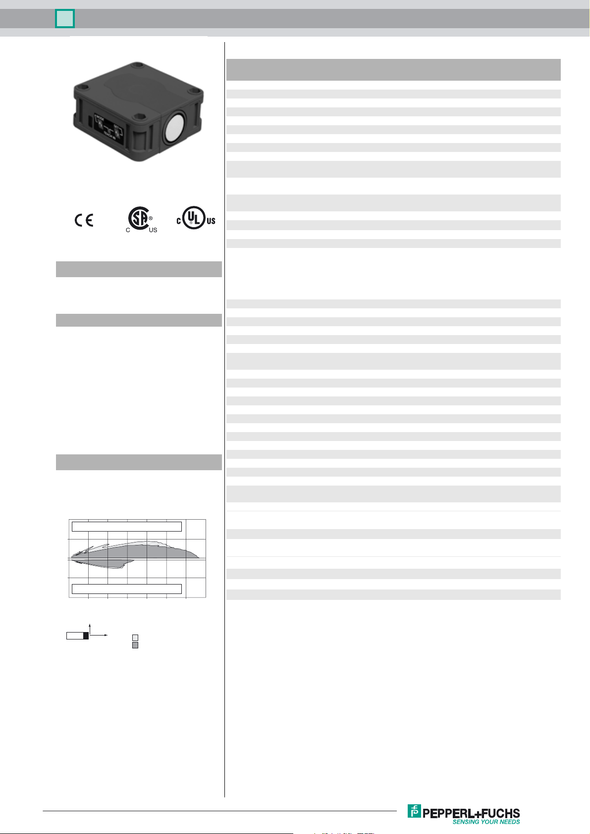
Characteristic response curve
Distance Y [m]
1
Flat surface 100 mm x 100 mm
0.5
0
-0.5
Round bar, Ø 25 mm
-1
0.0 0.5 1.0 1.5 2.0 2.5 3.0 3.5
Y
X
wide sonic beam
narrow sonic beam
Distance X [m]
LED yellow 1 solid: switching state switch output 1
LED yellow 2 solid: switching state switch output 2
LED red normal operation: "fault"
Electrical specifications
Operating voltage U
No-load supply current I
Input/Output
Synchronization bi-directional
Synchronization frequency
Common mode operation ≤ 30 Hz
Multiplex operation ≤ 30/n Hz, n = number of sensors
Output
Output type 2 switch outputs PNP, NO/NC selectable
Rated operating current I
Default setting Switch point A1: 90 mm , Switch point A2: 2000 mm , wide
Voltage drop U
Repeat accuracy ≤ 0.5 % of switching point
Switching frequency f ≤ 2.7 Hz
Range hysteresis H 1 % of the set operating distance
Temperature influence ± 1 % of full-scale value
Ambient conditions
Ambient temperature -25 ... 70 °C (-13 ... 158 °F)
Storage temperature -40 ... 85 °C (-40 ... 185 °F)
Mechanical specifications
Connection type Connector M12 x 1 , 5-pin
Degree of protection IP54
Material
Housing ABS
Transducer epoxy resin/hollow glass sphere mixture; foam
Mass 140 g
Compliance with standards and
directives
Standard conformity
Standards EN 60947-5-2:2007 + A1:2012
Approvals and certificates
UL approval cULus Listed, General Purpose
CSA approval cCSAus Listed, General Purpose
CCC approval CCC approval / marking not required for products rated
B
0
e
d
flashing: program function
flashing: program function
program function: no object detected
10 ... 30 V DC , ripple 10 %
≤ 50 mA
0 level -U
1 level: +4 V...+U
input impedance: > 12 KOhm
synchronization pulse: ≥ 100 µs, synchronization interpulse
period: ≥ 2 ms
200 mA , short-circuit/overload protected
sound lobe
≤ 2.5 V
polyurethane, cover PBT
IEC 60947-5-2:2007 + A1:2012
≤36 V
...+1 V
B
B
SS
Release date: 2016-02-26 11:31 Date of issue: 2016-02-26 133995_eng.xml
Refer to “General Notes Relating to Pepperl+Fuchs Product Information”.
1
Page 2
Ultrasonic sensor UB2000-F42S-E6-V15
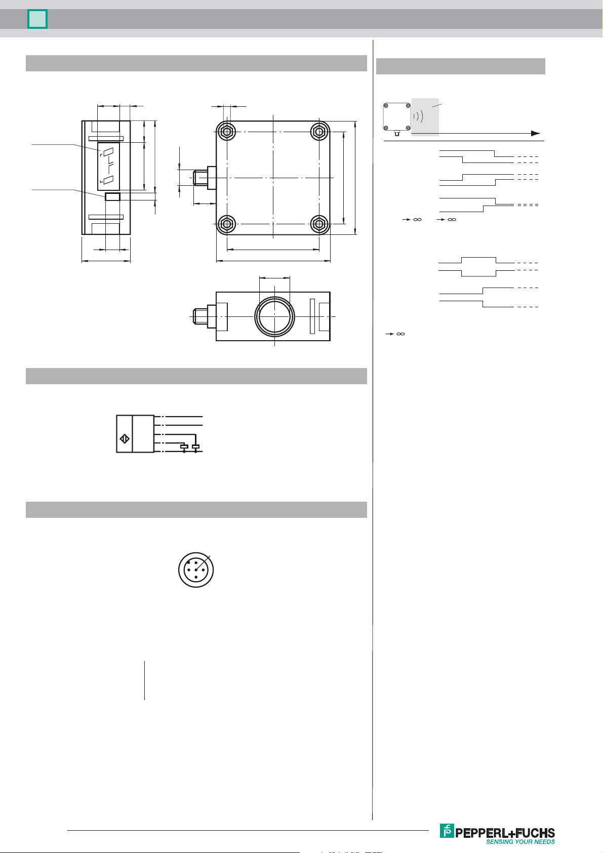
Dimensions
Membrane keys
LED window
Additional Information
Switching output programmation
7.5
15
15.5
2
A
TEACH IN
1
MODE SET
A
10
34
52.5
34
M12x1
5
16
5.2
Unusable area
Object distance
Mode 1:
output 1
output 2
Mode 2:
80
65
65
80
22
output 1
output 2
Mode 3:
output 1
output 2
A1 , A2 : Object presence detection.
Both outputs operate according to the selected mode,
if an object is located within the detection range.
Window and Switching point:
output 1
output 1
output 2
output 2
Note:
means: cover transducer surface with your hand,
while programming the output.
If A1 = A2, the output work like A1 < A2
A2
A1
A2
A2
A3
A3
A1
A2
A1
A2A1
A1
prog. with A1 key
prog. with A2 key
Electrical Connection
Standard symbol/Connections:
(version E6, pnp)
U
Core colours in accordance with EN 60947-5-2.
Pinout
Wire colors in accordance with EN 60947-5-2
1 BN
2 WH
3 BU
4 BK
5 GY
(BN)
1
(GY)
5
(BK)
4
(WH)
2
(BU)
3
2
+ U
B
Sync.
Switch output 1
Switch output 2
- U
B
1
5
4
3
(brown)
(white)
(blue)
(black)
(gray)
Release date: 2016-02-26 11:31 Date of issue: 2016-02-26 133995_eng.xml
Refer to “General Notes Relating to Pepperl+Fuchs Product Information”.
2
Page 3

Ultrasonic sensor UB2000-F42S-E6-V15
Accessories
MH 04-3505
Mounting aid for FP and F42 sensors
MHW 11
Mounting brackets for sensors
V15-G-2M-PVC
Female cordset, M12, 5-pin, PVC cable
Functional description
The sensor can be completely parameterised using 2 keys on the side of the housing. One special feature of this sensor is the
option of adapting the ultrasonic beam width to the ambient conditions at the place where the sensor is used.
Teach-in of switching points:
Teach-in of switching points is used to determine the points at which the switching outputs will change their state. In addition,
the order of switching points A1 < A2, or A1 > A2 also determines the effective direction (normally closed/open function) of the
window in the output function (operating mode) "Window + Switching point“ (see below).
Teach-in of switching point A1 with key A1
Press key A1 > 2 seconds The sensor goes into learning mode for switching point
Position the target object at
the desired distance
Press key A1 briefly The sensor completes the Teach-in process for switch-
A1
The sensor indicates by rapid flashing of the yellow
LED that the target object has been detected. If no object is detected, the red LED flashes.
ing point A1 and stores the value in permanent memory. If the object is uncertain (red LED lit irregularly) the
Teach-in value is not valid. Teach-in mode closes.
The process for Teach-in of switching point A2 is similar to what was described above, using key A2.
Special feature for output function "Window + switching point“
In the case of the output function (operating mode) "Window + switching point“ (see below), switching points A1 and A2 define
the window limits of switch output 1.
A third switching point A3 can also be defined here at which switch output 2 switches.
Teach-in of switching point A3 with keys A1 and A2
(only for operating mode window + switching point, see below)
Press key A1 + A2 > 2 seconds
Position the target object at
the desired distance
Press key A1 briefly
(output 2: normally closed)
or
Press key A2 briefly
(output 2: normally open)
The sensor goes into learning mode for switching point
A3
The sensor indicates by rapid flashing of the yellow
LEDs that the target object has been detected. If no object is detected, the red LED flashes.
The sensor completes the Teach-in process for switching point A3 and stores the value in permanent memory.
If the object is uncertain (red LED lit irregularly) the
Teach-in value is not valid. Teach-in mode closes.
Teach-in for switching points can only be performed within the first 5 minutes after turning on the power supply. If the switching
points need to be changed at a later time, this cannot be done until there is a new Power On.
Parameter assignment of the output function and ultrasound beam width
If you press the A1 key while the power supply is being turned on and then hold it down for 1 second, the sensor goes into the
two-level parameterisation of operating modes.
Level 1, parametrisation of the output function
Pressing the A2 key briefly will cause the possible output functions to be selected one after the other (depending on the last
output function to be parameterised). The functions are indicated by a flashing sequence of the green LED.
Release date: 2016-02-26 11:31 Date of issue: 2016-02-26 133995_eng.xml
Refer to “General Notes Relating to Pepperl+Fuchs Product Information”.
3
Page 4

Ultrasonic sensor UB2000-F42S-E6-V15
Operating mode Flashing sequence of green LED A2 key
2 x normally open function
(default)
2 x normally closed function
2 switching points
n.o. (output 1) +
n.c. (output 2)
Window (output 1) +
switching point (output 2)
Pause
Pause
Paus e
Paus e
Pressing the A1 key for 2 seconds saves the selected output operating mode. The parameter assignment process is then complete and the sensor returns to normal mode. If you press the A1 key briefly instead, you go to Level 2 (parameter assignment
of ultrasonic beam range).
Level 2, parameter assignment of ultrasonic beam width
The ultrasonic beam width can be adjusted to match the requirements of the application in Level 2.
Pressing the A2 key briefly will cause the possible beam widths to be selected one after the other (depending on the last beam
width to be parameterised). The functions are indicated by a flashing sequence of the red LED.
Beam width Flashing sequence of red LED A2 key
Narrow beam width
Average beam width
Pause
Pause
Wide beam
(default)
Paus e
Pressing the A1 key for 2 seconds saves the selected type of beam width. The parameter assignment process is then complete
and the sensor returns to normal mode. If you press the A1 briefly instead, you go back to Level 1 (parameter assignment of
output function).
If parameterisation is not complete within 5 minutes (pressing the A1 key for 2 seconds), the sensor interrupts parameterisation
mode without changing the settings.
Synchronisation
The sensor is equipped with a synchronisation connection to suppress mutual interaction. If it is not turned on, the sensor works
at an internally generated cycle rate. Synchronisation of more than one sensor is possible in a number of different ways.
External synchronisation:
The sensor can be synchronised by the application of a square wave voltage externally. A synchronisation pulse on the synchronisation input results in the execution of a measurement cycle. The pulse width must be greater than 100 µs. The measurement cycle must be started with the falling signal edge. A Low level > 1 s or an open synchronisation input results in normal
operation of the sensor. A High level on the synchronisation input deactivates the sensor.
Two different operating modes are possible
- Multiple sensors can be controlled by the same synchronisation signal. The sensors work on synonymous cycle.
- Synchronisation pulses are sent cyclically to only one sensor each time. The sensors work in Multiplex mode.
Self synchronisation:
The synchronisation connections of up to 5 sensors with option for self-synchronisation are connected with each other. These
sensors work after turning on the operating voltage in Multiplex mode. The On delay increases depending on the number of
sensors to be synchronised. Synchronisation is possible during Teach-in and vice-versa. Sensors must be operated unsynchronised to perform Teach-in of switching points.
Note:
If the option for synchronisation is not used, the synchronisation input can be connected with ground (0 V) or the sensor can be
operated with a V1 connection cable (4-pin).
Release date: 2016-02-26 11:31 Date of issue: 2016-02-26 133995_eng.xml
Refer to “General Notes Relating to Pepperl+Fuchs Product Information”.
4
 Loading...