

Page 1
U3
Force Transducers
Special features
– Tensile / compressive force
transducers
– Nominal forces 500 N ... 100 kN
– Integrated lateral force compen-
sation
– Low overall height
– Flanged ends on both side
– Sturdy design through high
dynamic load–carrying capacity
– Stainless steel housing
Data Sheet
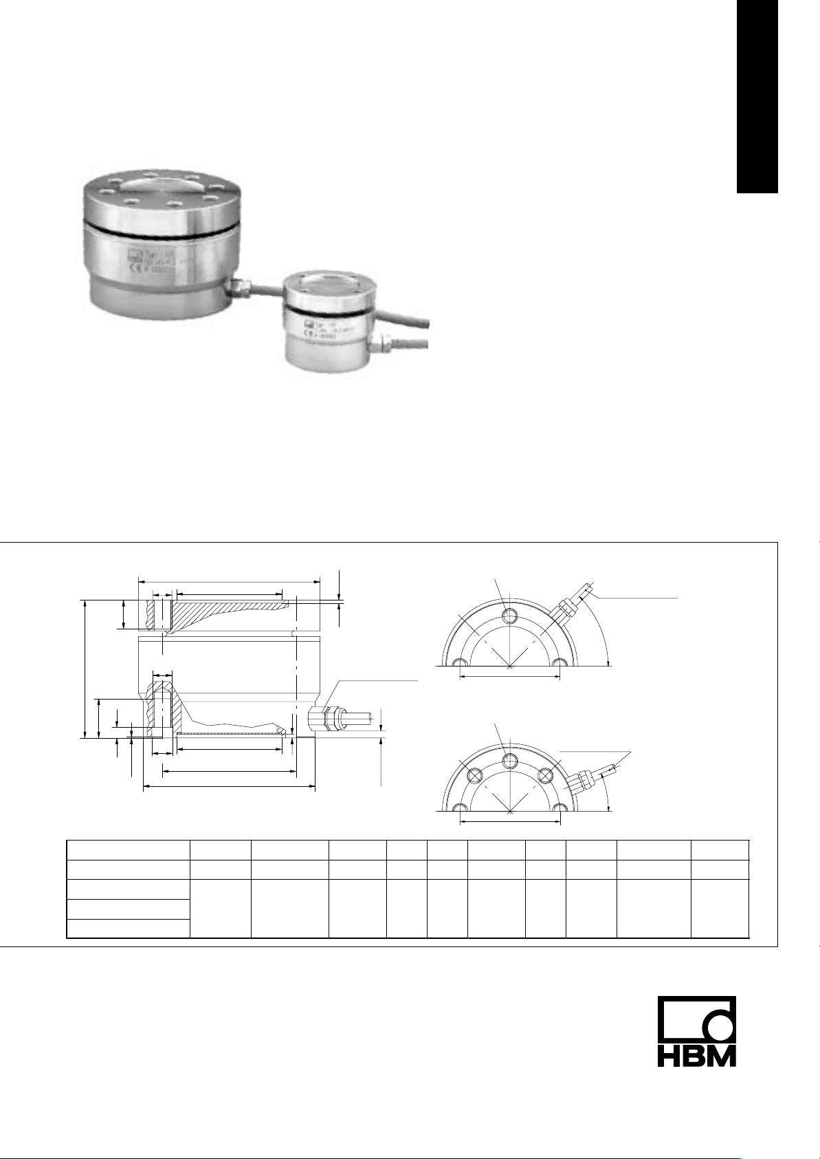
Dimensions (in mm; 1 mm= 0.03937 inches)
∅A
M
D
G
F
E
* only at 50 kN and 100 kN
Nominal force ∅A ∅B
U3/0.5–10 kN 54 50 34 8.5 5 13 47 5.5 42 M5
U3/20 kN
U3/50 kN
U3/100 kN
M
∅H
0.5*
∅C
3
∅C
∅K
∅B
–0.02
95 90 55 15 5.5 20.5 72 11 70 M10
1.5
Mini screwed joint
M8x1; a.f.11
approx. 3.5
H8
∅C
D E F G ∅H ∅K
4 x 90
∅K
8 x 45
∅K
o
o *
Cable length 3 m
U3: 0.5 – 20 kN
Cable length 3 m
o
45
U3: 50 kN/100 kN
o
22.5
"
0.1
M
20.U3.21 en
Page 2

Specifications (VDI/VDE 2638)
Type U3
Nominal force F
Accuracy class 0.2
Nominal sensitivity C
Rel. sensitivity deviation compressive
force
Rel. tensile/compressive force sensitivity
diff.
Relative zero signal deviation d
Relative range of inversion (0.5 Fnom to
u
Fnom)
Linearity deviation compressive force d
Linearity deviation tensile force d
Effect of temperature on sensitivity/10 K
TK
by reference to nominal sensitivity
Effect of temperature on zero signal/10 K
TK
by reference to nominal sensitivity
Effect of eccentricity at 1 mm d
Effect of transverse forces transverse force
10 % F
Relative creep over 30 min d
nom
1)
crF+E
Input resistance R
Output resistance R
Isolation resistance R
Reference excitation voltage U
Operating range of the excitation voltage B
Nominal temperature range B
Operating temperature range B
Storage temperature range B
Reference temperature t
Maximum operating force (FG) % 130 150 130
Limit force (FL) % 130 150 130
Breaking force (FB) % >300 250
Static lateral limit force
1)
(FQ) % 100 80 50
Permissible eccentricity e
Nominal displacement S
Fundamental resonance frequency F
Relative permissible vibrational stress F
Weight kg approx. 0.6 approx. 2.5
Degree of protection to DIN EN60529 IP65
Cable length, six–wire connection m 3
1)
by reference to a force introduction point on the force–introduction surface
kN 0.5 1 2 5 10 20 50 100
nom
mV/V 2
nom
< "0.2
d
% <2 <1
zd
% <1
s.o
% <0.2
0.5
% <0.2
lin
% <0.3 <0.2
lin
% <0.2 <0.1
c
% <0.1
0
% <"0.1
E
d
% <"0.1 <"0.2
Q
% <"0.1
Ω >345
e
Ω 300 – 400
a
Ω >2x 10
is
V 5
ref
U.GT
t.nom
V 0.5 to 12
o
C –10 to +70
o
C –30 to +85
t.G
o
C –50 to +85
t.S
o
C +23
ref
mm 25 40 32 20
G
mm <0.08 <0.1
nom
kHz 1.3 2.1 3.1 5.2 7.1 3.7 5.7 7.25
G
% 100 160
rb
9
Accessories (to order):
’Complete adapter’ for knuckle eye mounting Knuckle eye 1–ZGUW
0.5–10 kN Order no. 2–9289.1956 0.5–10 kN Order no. 1–U2A/1t/ZGUW
20 kN Order no. 2–9289.1957 20 kN Order no. 1–U2A/2t/ZGUW
50 kN Order no. 2–9289.1958 50 kN Order no. 1–U2A/5t/ZGUW
100 kN Order no. 2–9289.2280 100 kN Order no. 1–Z4/100kN/ZGUW
D 20.U3.21 enHBM 2
Page 3

Installation and accessories
Installation without Adapter
M
A
provided by customer
Flange
Base
provided by customer
M
A
Nominal force (kN) Starting torque MA (Nm) Thread
0.5 – 10 5 4 x M5
20 40 4 x M10
50 40 8 x M10
100 94 8 x M10–12.9 DIN912 galvanised
Installation with adapter and knuckle eye
M2 (MA)
provided by customer
base
Hmax.
adapter
flange
flat
M1 (MA)
lock nut, M
B
ZGUW/1 – 5T/100kN
Nominal force
(kN)
0.5 – 10 108 5 60 M5x12 M5
20 170 40 300 M10x25 M10
50 180 40 500 M10x25 M10
100 187 94 1000 M10x25 M10
H
Max
(mm)
Starting torque MA (Nm) Starting torque MB (Nm) Screws for adapter mounting
M1 M2
D 20.U3.21 en HBM
3
Page 4

Mounting accessories
Knuckle eye ZGUW
W
H
H7
B
∅
a.f.
A
G
Material: tempering steel, galvanised; rolled steel and PTFE/bronze fabric foil
D
G
N
F
Adapter
A
C
D
f8
M
K
SW
L
S
R
Q
P
Knuckle eye
H7
H7
D F G H M X W a./f. Weight (kg)
70 110 145 25 M30x2 24 37 46 1.1
Nominal force
(kN)
0.5...10 33.5 12 32 54.5 70.5 12 M12 7 16 19 0.1
20 47 20 50 79.8 104.8 18 M20x1.5 9 25 30 0.4
50 57 25 60 94.5 124.5 22 M24x2 10 31 36 0.6
100 66 30
A ∅B
Adapter
Nominal
force
(kN)
0.5...10 50 42 34 M12 14 22 4x5.5 4.5 19 25.1 0.9 19 0.15
20 90 70 55 M20x1.5 22 34 4x11 4.5 15 40.1 0.9 30 1.3
50 90 70 55 M24x2 26 42 8x11 6 20 45.1 0.9 36 1.45
100 90 70 55 M30x2 26 42 8x11 6 20 45.1 0.9 41 1.45
1)
including screws
∅A ∅C ∅D
f8
M ∅K ∅L ∅N P Q R S a./f. Weight1) (kg)
Modifications reserved.
All details describe our products in general form only. They
are not to be understood as express warranty and do not
constitute any liability whatsoever.
D 20.U3.21 en
Hottinger Baldwin Messtechnik GmbH
Postfach 10 01 51, D-64201 Darmstadt
Im Tiefen See 45, D-64293 Darmstadt
Tel.: +49/61 51/ 8 03-0; Fax: +49/61 51/ 8039100
E–mail: support@hbm.com www.hbm.com
 Loading...