

Datasheet SMP30-120, SMP30-130, SMP30-180, SMP30-200, SMP30-220 Datasheet (SGS Thomson Microelectronics)
...Page 1

SMP30-xxx Series
FEATURES
n BIDIRECTIONAL CROWBAR PROTECTION.
n VOLTAGE RANGE: FROM 62 V TO 270 V.
n HOLDING CURRENT :
IH= 150 mA min.
n REPETITIVE PEAK PULSE CURRENT :
IPP= 30 A, 10/1000 µs.
n JEDEC REGISTERED PACKAGE OUTLINE
DESCRIPTION
The SMP30-xxx series has been designed to
protect telecommunication equipments against
lightning surges and overvoltages induced by AC
power lines.
SMA
(JEDEC DO-214AA)
SCHEMATIC DIAGRAM
TRISIL
TM
COMPLIES WITH THE
FOLLOWING STANDARDS:
(CCITT) ITU-K20
Peak Surge
Voltage
(V)
1000 10/700 5/310 25 -
Voltage
Waveform
(µs)
Current
Waveform
(µs)
Admissible
Ipp
(A)
Necessary
(CCITT) ITU-K17 1500 10/700 5/310 38 VDE0433
2000 10/700 5/310 40 10
VDE0878 2000 1.2/50 1/20 50 IEC-1000-4-5
FCC Part 68, lightning surge
type A
FCC Part 68, lightning surge
level 2
level 3
1500
800
10/700
1.2/50
10/160
10/560
5/310
8/20
10/160
10/560
25
50
65
50
1000 9/720 5/320 25 type B
BELLCORE TR-NWT-001089
First level
BELLCORE TR-NWT-001089
2500
1000
2/10
10/1000
2/10
10/1000
125
30
5000 2/10 2/10 125 15.0
Second level
BELLCORE TR-NWT-001089
1500 2/10 2/10 100 Intra building lightning
CNET l31-24 1000 0.5/700 0.8/310 25 -
January 2000 - Ed: 5B
Resistor
(Ω)
-
-
15.5
8.0
15.0
23.3
1/6
Page 2
SMP30-xxx Series
ABSOLUTE MAXIMUM RATINGS (T
amb
=25°C)
Symbol Parameter Value Unit
P Power dissipation on infinite heatsink T
IPPPeak pulse current 10/1000 µs
I
TSM
I2t
Non repetitive surge peak on-state current tp = 20 ms 15 A
I2t value for fusing
dV/dt Critical rate of rise of off-state voltage V
T
stg
T
j
T
L
Storage temperature range
Maximum junction temperature
Maximumleadtemperatureforsolderingduring10sat5mmforcase
=50°C3 W
amb
30
8/20 µs
60
tp = 20 ms 1 A2s
RM
5 kV/µs
- 55 to + 150
150
260 °C
THERMAL RESISTANCES
Symbol Parameter Value Unit
Rth(j-l) Junction to leads 30 °C/W
Rth(j-a)
Junction to ambient on printed circuit
120 °C/W
with standard footprint dimension
A
°C
°C
ELECTRICAL CHARACTERISTICS
(T
=25°C)
amb
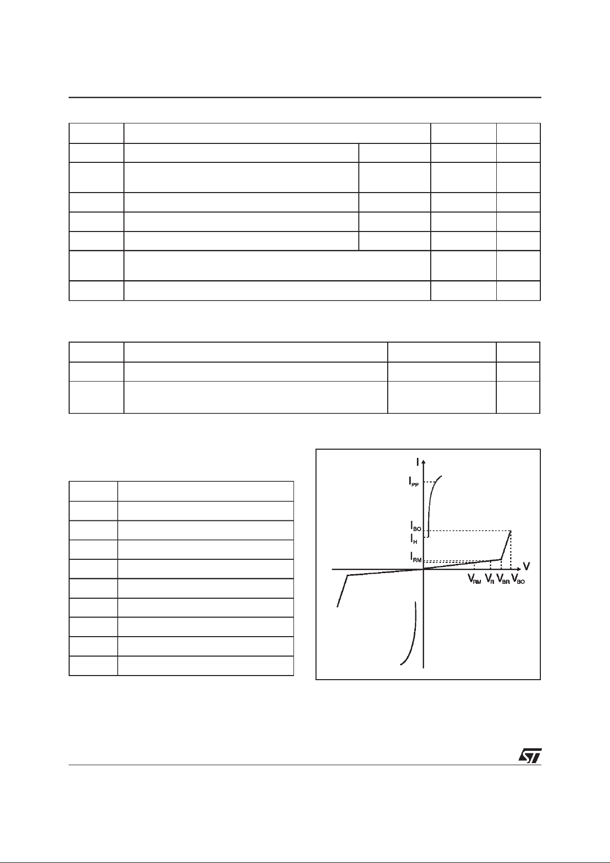
Symbol Parameter
V
RM
I
RM
V
V
BR
V
BO
I
H
I
BO
I
PP
Stand-off voltage
Leakage current at stand-off voltage
Continuous Reverse voltage
R
Breakdown voltage
Breakover voltage
Holding current
Breakover current
Peak pulse current
C Capacitance
2/6
Page 3

SMP30-xxx Series
Type
Marking IRM@V
RM
max max
note 1
µAVµAV VmAmA pF
SMP30-62
SMP30-68
SMP30-100
SMP30-120
SMP30-130
SMP30-180
SMP30-200
SMP30-220
SMP30-240
SMP30-270
Note 1: IRmeasured at VRguarantee V
Note 2: Measured at 50 Hz(1cycle) - See test circuit1.
Note 3: See test circuit 2.
Note 4: VR= 1V, F =1MHz.
Note 5: VR= 50V,F = 1MHz
QAA
QAB
QAC
QAD
QAE
QAF
QAG
QAH
QAI
QAJ
2
2
2
2
2
2
2
2
2
2
BRmin
108
117
162
180
198
216
243
V
56
61
90
50
50
50
50
50
50
50
50
50
50
R
TEST CIRCUIT 1 FORIBOand VBOparameters :
tp
Auto
Transfo r m er
220V/2A
static
relay.
IR@V
100
120
130
180
200
220
240
270
=20ms
R
62
68
note 2
R1
140
R2
240
VBO@I
max
82
90
133
160
173
240
267
293
320
360
BO
800
800
800
800
800
800
800
800
800
800
I
H
min
note 3
150
150
150
150
150
150
150
150
150
150
typ
note 4
50
50
40
40
35
35
30
30
30
30
C
typ
note 5
20
20
16
16
14
14
12
12
12
12
V
out
I
220V
Transformer
220V/800V
5A
BO
measure
TEST PROCEDURE :
n Pulse Test duration (tp = 20ms):
- For Bidirectional devices = Switch K is closed
- For Unidirectional devices = Switch K is open.
n V
OUT
Selection
- Device with VBO< 250 Volt
-V
OUT
= 250 V
RMS,R1
= 140 Ω.
- Device with VBO 250 Volt
-V
OUT
= 480 V
RMS,R2
= 240 Ω.
K
D.U.T
V
BO
measure
3/6
Page 4

SMP30-xxx Series
TEST CIRCUIT 2 for IHparameter.
R
-V
P
V
BAT
D.U.T .
= - 48 V
Surge generator
This is a GO-NOGO Test which allows to confirm the holding current (IH) level in afunctional test circuit.
TEST PROCEDURE :
n 1) Adjust the current level at the I
value by short circuiting the AK of the D.U.T.
H
2) Fire the D.U.T with a surge Current : Ipp = 10A , 10/1000 µs.
3) The D.U.T will come back off-state within 50 ms max.
4/6
Page 5

SMP30-xxx Series
Fig. 1: Non repetitive surge peak on-sate current
versus overload duration (Tj initial=25°C).
ITSM(A)
20
F = 50Hz
15
10
5
0
1E-2 1E-1 1E+0 1E+1 1E+2 1E+3
t(s)
Fig. 3: Relative variation of junction capacitance
versus reverse applied voltage (typical values)
C[VR]/C[VR=1V]
1.0
F = 1MHz
0.5
Fig. 2: Relative variation of holding currentversus
junction temperature.
IH[Tj] / IH[Tj=25°C]
2.0
1.8
1.6
1.4
1.2
1.0
0.8
0.6
0.4
0.2
0.0
-40 -20 0 20 40 60 80 100 120
Tj(°C)
Fig. 4: On-state voltage versus on-state current
(typical values).
IT(A)
50
Tj = 25°C
20
10
0.2
0.1
1 10 100 300
VR(V)
Fig. 5: Variation of thermal impedance junction to
ambient versus pulse duration.
Zth(j-a)(°CW)
1E+2
1E+1
1E+0
1E-1
1E-3 1E-2 1E-1 1E+0 1E+1 1E+2 5E+2
tp(s)
5
2
1
012345678910
VT(V)
Fig. 6: Relative variation of VBOvoltage versus
junction temperature.
Vbo[Tj]/Vbo[Tj=25°C]
1.10
1.05
1.00
270 V
0.95
62V
0.90
-40 -20 0 20 40 60 80 100
Tj(°C)
5/6
Page 6

SMP30-xxx Series
ORDER CODE
SMP 30 - 62
SURFACE MOUNT PROTECTION
MARKING : Logo, Date Code, Part Number.
PACKAGE MECHANICAL DATA
SMA (JEDEC DO-214AA)
E1
D
E
A1
C
L
A2
IPP=30A
b
VOLTAGE
DIMENSIONS
REF.
Millimeters Inches
Min. Max. Min. Max.
A1 1.90 2.70 0.075 0.106
A2 0.05 0.20 0.002 0.008
b 1.25 1.65 0.049 0.065
c 0.15 0.41 0.006 0.016
E 4.80 5.60 0.189 0.220
E1 3.95 4.60 0.156 0.181
D 2.25 2.95 0.089 0.116
L 0.75 1.60 0.030 0.063
FOOT PRINT (in millimeters)
Weight: 0.06 g
Packaging : Tape and reel.
1.65
2.40
1.45 1.45
Information furnishedis believedto be accurateand reliable.However, STMicroelectronicsassumes noresponsibilityfortheconsequences of
use ofsuch informationnor foranyinfringement ofpatents orother rights ofthird partieswhich mayresult from itsuse. Nolicense isgranted by
implication or otherwise under any patent or patent rights of STMicroelectronics. Specifications mentioned in this publication are subject to
change without notice. Thispublication supersedes and replaces allinformation previously supplied.
STMicroelectronics products are not authorized for useascritical componentsin life support devices or systems without express written approval of STMicroelectronics.
The ST logo is a registered trademark of STMicroelectronics
2000 STMicroelectronics - Printed in Italy - All rights reserved.
STMicroelectronics GROUP OF COMPANIES
Australia - Brazil - China - Finland - France - Germany - Hong Kong - India - Italy - Japan - Malaysia
Malta - Morocco - Singapore - Spain - Sweden - Switzerland - United Kingdom - U.S.A.
http://www.st.com
6/6
 Loading...