

Page 1
SMP402
PI-555A-123091
48 VDC
5 VDC
+
-
+
-
SMP402
OUT
PI-553B-012892
POLARITY
V
S
EA IN
EA OUT
V
BIAS
C
EXT
V
IN
V
LS
ENABLE
D GND
SENSE -
R
EXT
16
15
14
13
12
11
10
9
1
2
3
4
5
6
7
8
LEVEL
A GND
SENSE+
1-Watt Buck Regulator IC
20-72 VDC Input
Non-isolated DC Output
Product Highlights
Integrated Power Switch and CMOS Controller
• Output power > 1 W from 48 VDC input
• Adjustable output voltage
• Integrated solution minimizes overall size
High-voltage, Low-capacitance MOSFET Output
• Designed for ISDN T1 telecommunications applications
• Low capacitance allows for high frequency operation
High-voltage Buck Regulator
• Internal pre-regulator self-powers the IC on start-up
• Designed for low power consumption
• Minimum external parts required
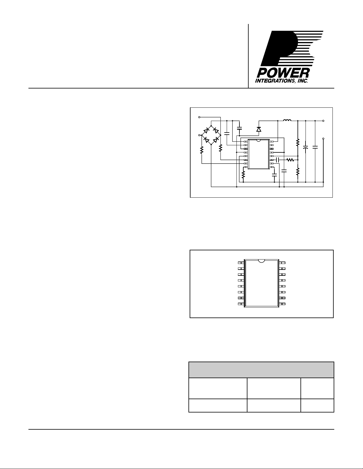
Figure 1. Typical Application.
Built-In Self-protection Circuits
• Undervoltage lockout
• Thermal shutdown
• Input polarity/level sense
®
Description
The SMP402, intended for non-isolated ISDN
telecommunications power supply applications, combines a
high voltage power MOSFET switch with a switchmode power
system controller in a monolithic integrated circuit. Few
external components are required to implement a low cost
power supply which meets stringent ISDN specifications. High
frequency operation reduces total power supply size.
The P-channel power MOSFET switch features include high
voltage, low R
results in a reduction in gate drive power, and also facilitates
higher frequency operation.
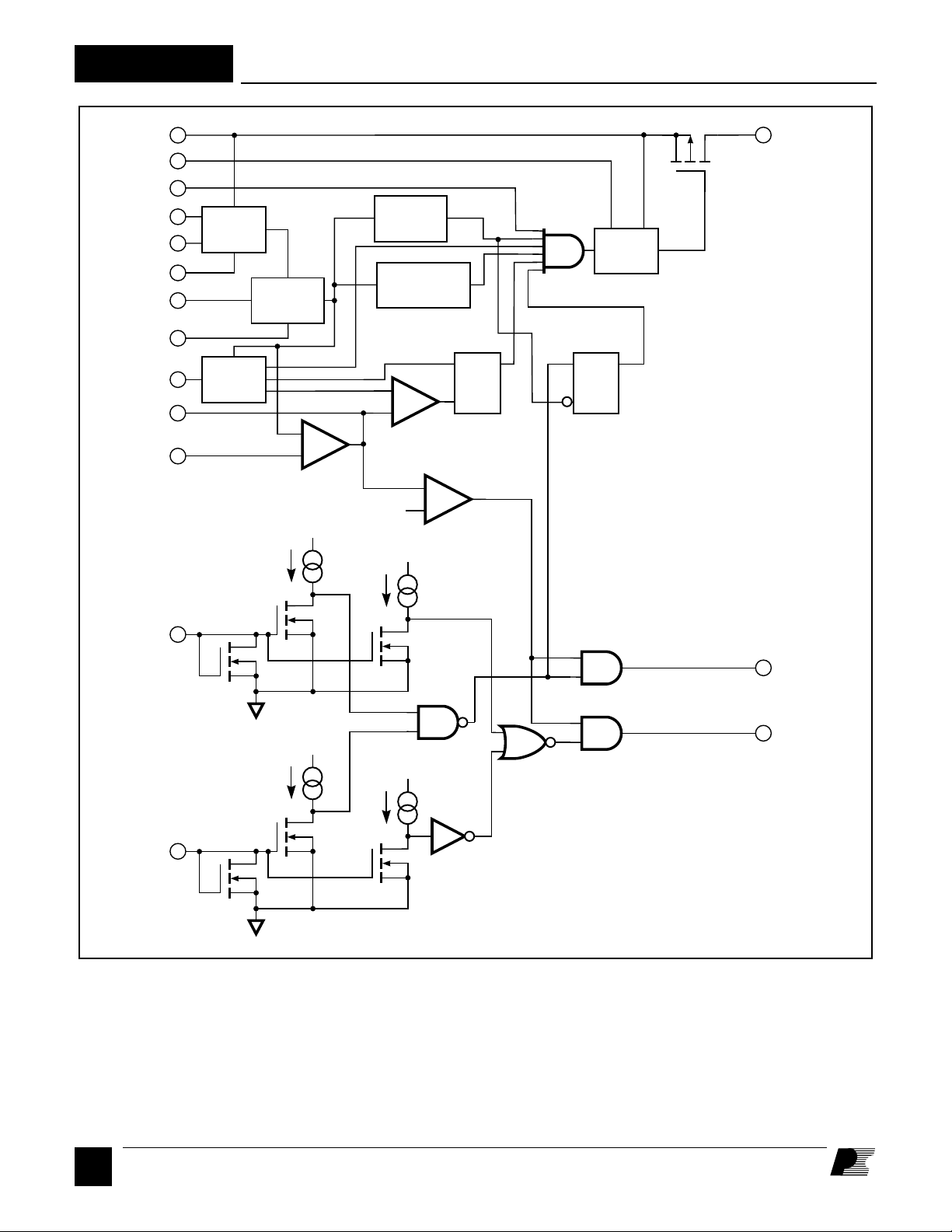
The controller section of the SMP402 contains all the blocks
required to drive and control the power stage: start-up preregulator circuit, oscillator, bandgap reference, error amplifier,
gate driver and level shift. Protection features include
undervoltage lockout, thermal shutdown, and input polarity
and level sensing.
The SMP402 is available in a 16-pin plastic SOIC package.
, and low capacitance. Lower capacitance
DS(ON)
Figure 2. Pin Configuration.
ORDERING INFORMATION
PART PACKAGE T
NUMBER OUTLINE RANGE
SMP402SC S16A 0 to 120°C
j
January 1996
Page 2
SMP402
V
IN
V
LS
ENABLE
V
BIAS
V
A GND
R
EXT
D GND
C
EXT
EA OUT
EA IN
OUT
HV
S
REG
V
REF
UV
LOCKOUT
LEVEL
SHIFT
THERMAL
BANDGAP
SHUTDOWN
REF
OSC
SRQ
+
-
+
-
PWM COMPARATOR
SRQ
ERROR
AMPLIFIER
23 µA
V
S
5 µA
4 V
+
V
S
SENSE+
23 µA
SENSE-
Figure 3. Functional Block Diagram.
LEVEL
V
S
V
S
5 µA
POLARITY
PI-552B-062293
D
2
1/96
Page 3

Pin Functional Description
SMP402
Pin 1:
V
is the high-voltage input to the
IN
switching regulator. This is the Source
connection of the P-Channel power
MOSFET pass transistor.
Pin 2:
V
is an internal supply for the level
LS
shift circuit that drives the P-Channel
MOSFET. A capacitor should be placed
between VLS and VIN for bypassing. V
is normally 10 V below VIN.
Pin 3:
The power supply can be shut down by
pulling ENABLE low.
Pin 4:
D GND is the common return point for
the power and logic portions of the
circuit.
Pin 5:
A GND is the common return point.
R
EXT
and C
are directly connected to
EXT
this point.
Pin 6:
The SENSE+ input monitors the polarity
and level of the input voltage through an
external resistor for ISDN emergency
Pin 11:
EA OUT is the error amplifier output
pin for connection to the external
compensation network.
standby sensing.
Pin 12:
Pin 7:
The SENSE- input monitors the polarity
and level of the input voltage through an
EA IN is the error amplifier negative
input for connection to the feedback and
compensation networks.
external resistor for ISDN emergency
LS
standby sensing.
Pin 13:
VS is the internal supply voltage. This
Pin 8:
pin is brought out for external bypassing.
A 20.5 kΩ resistor connected between
R
and A GND sets the internal bias
EXT
currents including oscillator charge and
discharge currents.
Pin 14:
The LEVEL output indicates when the
input voltage is in its normal operating
range.
Pin 9:
The oscillator frequency can be
programmed by selecting the value of
the capacitor connected between C
EXT
and A GND.
Pin 10:
V
can be connected to the output 5 V
BIAS
rail of the converter to reduce power
Pin 15:
The POLARITY output is used to notify
a microprocessor of an emergency
standby condition for ISDN applications.
Pin 16:
OUT is the Drain connection of the P-
Channel pass transistor.
dissipation. The internal 5 V regulator is
cut off when the output is in regulation.
Functional Description
High Voltage Regulator
The high-voltage regulator provides the
bias current required by the controller
and driver circuitry. The pre-regulator
consists of a high voltage MOSFET, a
gate bias current source, and an error
amplifier. The error amplifier regulates
VS to approximately 5 V by controlling
the gate of the MOSFET.
In 5 V output applications, the control
circuitry may also be operated by
connecting the V
V rail of the converter to reduce power
dissipation. The internal 5 V regulator is
cut off automatically when the converter
output is in regulation. Only the supply
pin to the output 5
BIAS
current for the level shift stage (≈50 µA)
and the AC switching currents for the PChannel output device are drawn from
the VIN supply under this condition. If
unused, V
must be hardwired to A
BIAS
GND to disable the automatic switchover
during power-up.
VLS is the level-shift supply for driving
the gate of the internal P-channel
MOSFET. The voltage at VLS is
approximately 10 V below VIN. VS is the
supply voltage for the controller and
driver circuitry. External bypass
capacitors connected to VLS and VS are
required for filtering and reducing noise.
UV Lockout
During power-up, the undervoltage
lockout circuit keeps the P-channel
output transistor in the off state until the
internal VS supply is in regulation and
the voltage sensed by the input monitor
circuit is within the normal operation
range (>12 V).
Band Gap Reference
V
is the 1.3 V reference voltage
REF
generated by the temperature-
compensated bandgap reference and
buffer. This voltage is used for setting
thresholds for the error amplifier and
over temperature circuit.
D
3
1/96
Page 4
SMP402
Functional Description (cont.)
Oscillator
The oscillator frequency can be adjusted
by changing the external C
capacitor.
EXT
This capacitor is charged and discharged
by switched constant current sources.
The voltage switch points are determined
by hysteresis built into a comparator.
The period of the waveform is
determined by values of the current
sources which set the rising and falling
slopes of the sawtooth waveform.
Maximum duty cycle is equal to the ratio
of the charge time to the period. Clock
and blanking signals are synthesized
from the comparator output for use by
the modulator.
Error Amplifier
The error amplifier consists of a high
performance operational amplifier with
the non-inverting input connected to the
internal bandgap reference voltage. The
output of the error amplifier directly
controls the duty cycle of the power
switch.
Pulse Width Modulator
The pulse width modulator implements
a voltage-mode control loop, and
generates the digital driver signal which
controls the power switch. The duty
cycle of the driver signal will change as
a function of input voltage and load.
Increasing the duty cycle causes the
power supply output voltage to go up.
Conversely, decreasing the duty cycle
causes the output voltage to go down.
The pulse width modulator compares
the control voltage (error amplifier
output) with the sawtooth voltage
generated by the oscillator to produce
the required duty cycle.
Thermal Shutdown
Temperature protection is provided by a
precision analog circuit that turns the
power switch off when the junction gets
too hot (typically 140°C). The device
will automatically reset and turn back on
again when the junction has cooled past
the hysteresis temperature level.
SENSE+ and SENSE- Inputs
SENSE+ and SENSE-are both current
mirror inputs consisting of N-channel
MOSFETs connected as diodes. The
threshold voltage of each transistor is
typically 1.7 V. An input current which
exceeds the indicated threshold current
will turn on the mirror transistor for an
active-low signal.
POLARITY and LEVEL Outputs
The LEVEL output is high when the
input current to either SENSE+ or
SENSE- exceeds the LEVEL current
threshold and the output voltage is in
regulation. During normal operation,
the POLARITY output is high when the
input current to SENSE+ is above the
POLARITY current threshold and the
output voltage is in regulation. During
emergency operation (when the DC
input voltage is inverted), the
POLARITY output is low when the input
current to SENSE- exceeds the
48 V
32 V
INPUT
5 V OUT
LEVEL
POLARITY
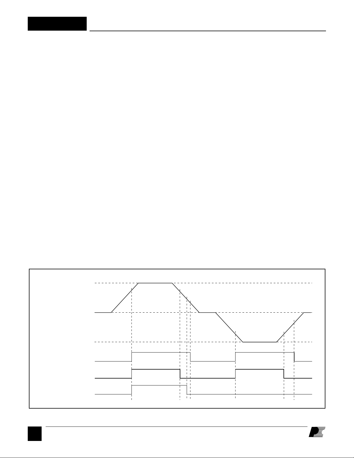
Figure 4. Turn-on and Turn-off Waveforms of the SMP402.
D
4
1/96
0
-48 V
5 V
0 V
5 V
0 V
5 V
0 V
30 V
12 V
10 V
-32 V
-10 V
-30 V
PI-960A-032293
Page 5
Functional Description (cont.)
SMP402
POLARITY current threshold.
Regulation of the output voltage is
detected by a comparator which looks
for error amplifier saturation in the output
high (maximum duty cycle) state.
Power supply turn on and turn off with a
slowly changing input voltage is shown
in Figure 4 as measured using the circuit
shown in Figure 6. Also shown are the
level and polarity outputs. The input
voltage must rise above 32 V before the
SMP402 will turn on. At this input
voltage the current through R1 into the
SENSE+ input exceeds the threshold
current (typically 23 µA), the LEVEL
and POLARITY outputs go high, and
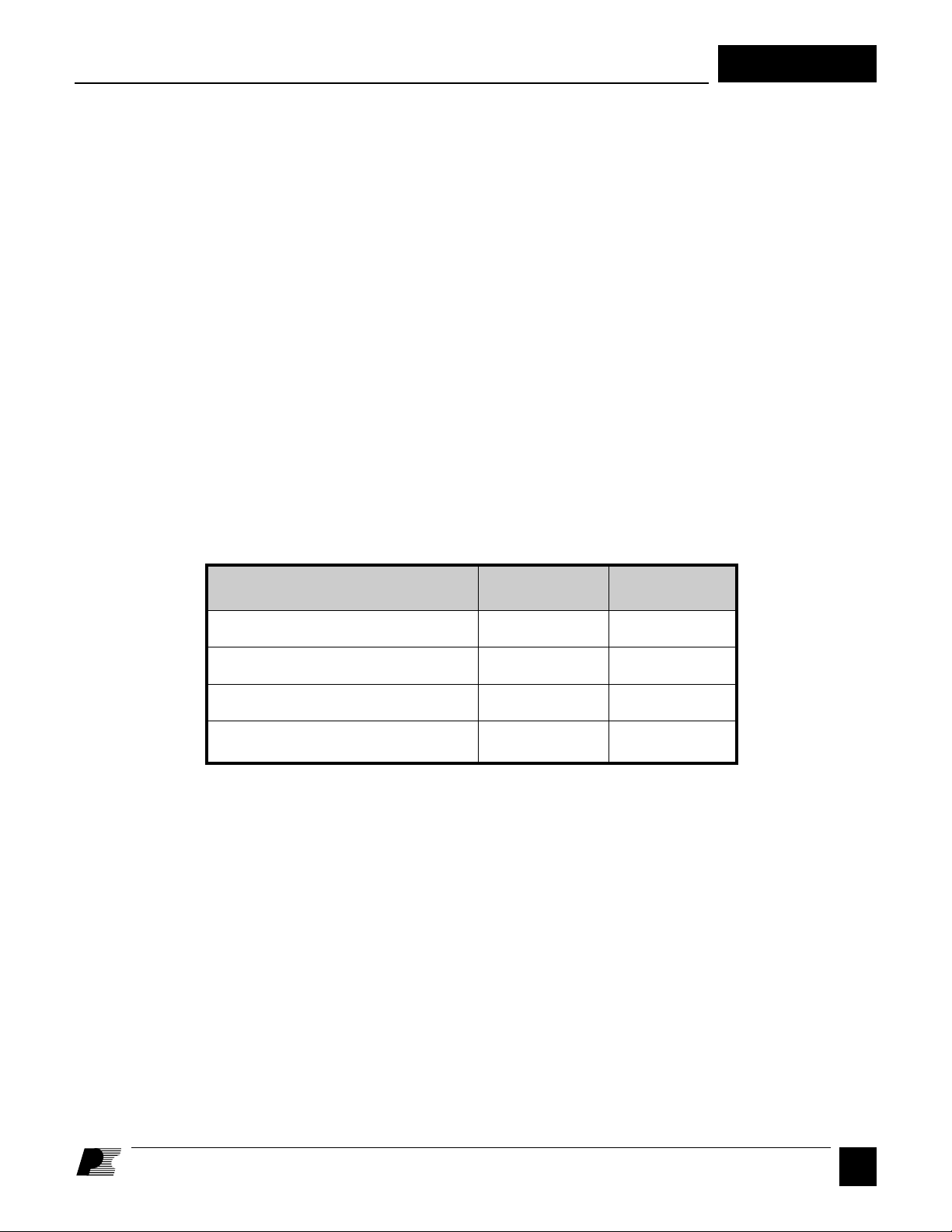
INPUT VOLTAGE CONDITION POLARITY LEVEL
the power supply turns on. As the input
voltage goes down, LEVEL will go low
at approximately 30 V, but POLARITY
will stay high. As the input voltage
continues to drop, POLARITY goes low
at approximately 12 V and the converter
loses regulation at approximately 10 V
and turns off. The LEVEL output will
go high and the power supply turns on
when the input voltage reaches -32 V.
POLARITY stays low to indicate that
the input voltage has reversed polarity.
As the negative input voltage falls toward
zero, LEVEL goes low at approximately
-30 V and the converter loses regulation
and turns off at approximately -10 V.
Enable
The power supply can be shut down by
pulling the ENABLE pin low. It is
internally pulled up to VS with a 100 µA
(nominal) current source. However, it is
recommended that this pin be tied to V
if it is unused.
P-Channel Output Transistor
The output MOSFET is a 90 V pass
transistor capable of supplying >200
mA. To minimize switching noise and
EMI, it is important to keep the path
from OUT through the output diode, the
input storage capacitor, and into VIN as
short as possible.
S
Negative voltage, level too low 0 0
Negative voltage, correct level 0 1
Positive voltage, level too low 1 0
Positive voltage, correct level 1 1
Figure 5. LEVEL/POLARITY Truth Table. The LEVEL and POLARITY signals are only valid when the output voltage is in regulation.
1/96
D
5
Page 6
SMP402
L1
+
INPUT
D1
-
D3 D4
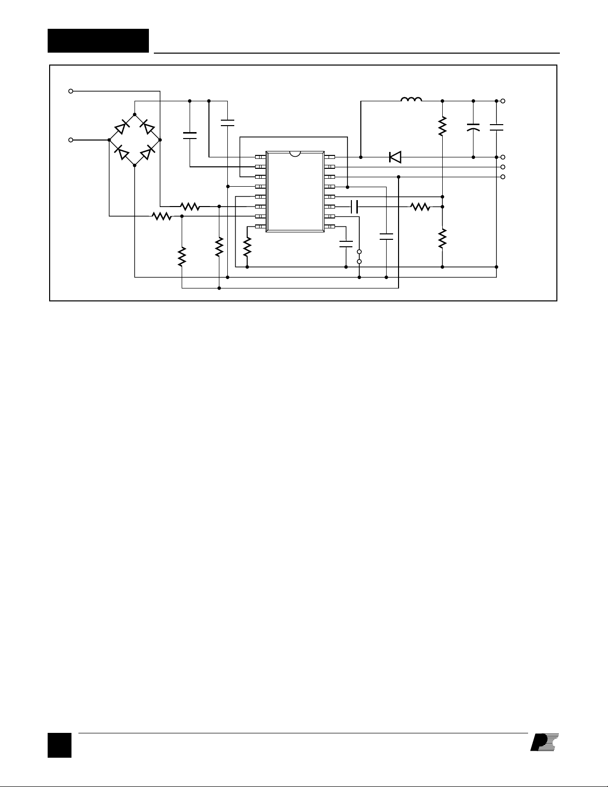
Figure 6. Schematic Diagram of a Non-isolated 5 V, 1 W ISDN Regulator Circuit Utilizing the SMP402.
4X
1N4002
D2
100 nF
R2
1.2 MΩ
R7
3.3 MΩ
C5
1.2 MΩ
R1
R8
3.3 MΩ
C1
1
2
3
4
5
6
7
8
R3
20.5 kΩ
U1
SMP402SC
16
15
14
13
12
11
10
9
C11
120 pF
C4-1 nF
C3
100 nF
JMP 1
470 µH
D6
UF4002
75 kΩ
R4
240 kΩ
R5
C2
82 µF
R6
24.9 kΩ
V
OUT
C6
100 nF
RTN
POLARITY
LEVEL
PI-1455-042695
General Circuit Operation
The Buck DC-to-DC converter shown
in Figure 6 produces a single non-isolated
5 V, 1 W power supply. The highvoltage P-channel MOSFET transistor
in the SMP402 is turned on and off at the
switching frequency. The ratio of ONtime to the switching period is defined as
the duty cycle. The duty cycle changes
with input voltage to maintain a constant
average value of the switching
waveform. The switching waveform is
filtered by inductor L1 and capacitor C2
to produce the 5 V output. During the
MOSFET ON-time, the switch current
and inductor current ramp up at a linear
rate. During the P channel MOSFET
switch off time, the voltage across L1
reverses, forward biasing D6. Inductor
and diode current then ramp down
linearly until the MOSFET turns on
again. During normal operation,
inductor current ramps up and down
around the average value (I
actually the DC load current.
), which is
OUT
The 5 V output voltage is directly sensed
and accurately regulated by an internal
error amplifier. The error amplifier
generates an error signal which directly
controls the duty cycle of the integrated
high-voltage P-channel MOSFET
switch. The effective output voltage can
be fine-tuned by adjusting the resistor
divider formed by R5 and R6. Other
output voltages are possible (up to
approximately half the input voltage) by
changing the value of L1 as well as the
resistor divider.
Polarity of the DC input voltage can be
either positive or negative. D1, D2, D3,
and D4 “rectify” the DC input voltage to
provide a positive polarity input voltage
for the converter. C1 provides input
voltage filtering. The SMP402 contains
the integrated controller and high-voltage
P-channel MOSFET which, together
with D6, generates a pulse width
modulated switching AC voltage
waveform. L1 and C2 filter the AC
voltage to create the 5 V output. C6
filters high-frequency noise currents. R5
and R6 sense and divide the 5 V output
voltage for comparison with the internal
bandgap reference voltage. C4 and R4
provide control loop compensation
feedback around the internal error
amplifier. C3 bypasses the onboard V
regulator. C11 sets the switching
frequency. R3 is fixed to set internal
currents accurately. C5 bypasses an
internally-generated, level-shifted bias
source of approximately 10 V, which is
referenced to the positive side of the
effective input voltage. This floating
supply is used for biasing the P-channel
MOSFET gate drivers. R1 and R2 sense
the level and polarity of the DC input
voltage. The current through R1 and the
SENSE+ input or R2 and the SENSEinput must exceed 23 µA before the
converter will turn on. R7 and R8
provide hysteresis for the SENSE+ and
SENSE- inputs. Jumper JMP1 disables
the self-bias feature of the SMP402.
S
D
6
1/96
Page 7
General Circuit Operation (cont.)
SMP402
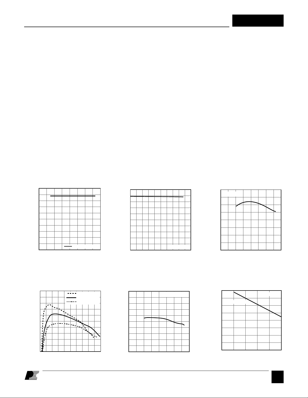
The line and load regulation graphs were
measured on the circuit shown in Figure
6. The switching frequency of the power
supply was measured at 230 kHz.
The maximum output power curve shows
the power output capability for a 470 µH
output filter inductor (L1).
The output power versus frequency curve
was generated by characterization of the
SMP402 at various frequencies. The
curve demonstrates the trade-off between
AC and DC power losses within the
device. As AC losses rise with frequency,
DC losses and output power must be
reduced to maintain the same device
maximum power dissipation.
Typical Performance Characteristics (Figure 6 Power Supply)
LINE REGULATION
105
104
103
102
101
Output Voltage (% of Nominal)
100
020406080
Input Voltage (VDC)
I
LOAD
= 200 mA
PI-939A-031393
LOAD REGULATION
105
104
103
102
101
Output Voltage (% of Nominal)
100
0 100 200 300 400 500
Load Current (mA)
VIN = 48 VDC
PI-938-022293
MAXIMUM OUTPUT POWER
2.0
TA = 25°C
1.5
1.0
Output Power (W)
0.5
0
020406080
PI-940-022293
Input Voltage (VDC)
EFFICIENCY vs. OUTPUT POWER
80
70
60
50
40
5 V Output Efficiency (%)
30
012
Load Power (W)
VIN = 24 VDC
VIN = 48 VDC
VIN = 72 VDC
PI-950-022593
EFFICIENCY vs. INPUT VOLTAGE
80
70
60
50
Output Efficiency (%)
40
30
020406080
Input Voltage (VDC)
I
LOAD
= 200 mA
PI-944-022293
OUTPUT POWER vs. FREQUENCY
2
VIN = 48 VDC
1
Output Power (W)
0
0 100 200 300 500
Switching Frequency (kHz)
TA = 25°C
400
D
1/96
7
PI-951-022593
Page 8
SMP402
ABSOLUTE MAXIMUM RATINGS
VIN Voltage.................................................................. 80 V
Drain-Source Voltage (VIN to OUT) ........................... 90 V
V
Voltage ..............................................................5.5 V
BIAS
SENSE Current .................................................... ±200 µA
OUT Voltage........................................VIN + 0.3 V to -4 V
OUT Current ..........................................................250 mA
Logic Input Voltage ........................... -0.3 V to VS + 0.3 V
Storage Temperature ..................................... –65 to 125°C
Operating Junction Temperature
(2)
. ................... 0 to 150°C
Conditions
(Unless Otherwise Specified)
Parameter Symbol V
= 48 V, V
IN
R
= 20.5 kΩ, C
EXT
RS+, RS- = 1.2 MΩ, Tj = 0 to 120°C
OSCILLATOR
Output
Frequency
Initial
Accuracy
f
OSC
∆f
OSC
C
= 30 to 300 pF
EXT
1
Lead Temperature
(3)
. ................................................ 260°C
Power Dissipation .....................................................1.0 W
Thermal Impedance (θJA) ...................................... 55°C/W
Thermal Impedance (θJC)
(4)
.................................... 15°C/W
1. Unless noted, all voltages referenced to A GND, TA=25˚C
2. Normally limited by internal circuitry.
3. 1/16" from case for 5 seconds.
4. Measured at pin 4/5.
= 5 V, GNDs = 0 V Min Typ Max Units
BIAS
= 120 pF
EXT
50 500
200 230 260
kHz
kHz
PULSE WIDTH MODULATOR
Duty
Cycle
DC
ERROR AMPLIFIER
Threshold
Voltage
V
REF
Gain-Bandwidth
Product
DC
Gain
Common-mode
Range
Output
Impedance
A
V
Z
VOL
EA IN
OUT
See Note 2
0-50 0-70
1.22 1.32
0.5
60 80
03
1
%
V
MHz
dB
V
kΩ
D
8
1/96
Page 9
Parameter Symbol V
CIRCUIT PROTECTION
Conditions
(Unless Otherwise Specified)
= 48 V, V
IN
R
= 20.5 kΩ, C
EXT
RS+, RS- = 1.2 MΩ, Tj = 0 to 120°C
= 5 V, GNDs = 0 V Min Typ Max Units
BIAS
= 120 pF
EXT
SMP402
Thermal Shutdown
Temperature
Thermal Shutdown
Hysteresis
LOGIC
Input Current
High
Input Current
Low
Input Voltage
High
Input Voltage
Low
Output Voltage
High
Output Voltage
Low
VIH = 3.0 V
VIL = 0 V
I
IH
I
IL
V
IH
V
IL
V
OH
V
OL
IOH = -0.5 mA
IOL = 0.5 mA
120 140
15
10 50
-500 -100
1.0
3.5
3.0
0.4
°C
°C
µA
µA
V
V
V
V
SENSE INPUTS
Threshold
Voltage
LEVEL
Threshold Current
POLARITY
Threshold Current
OUTPUT
ON-State
Resistance
ON-State
Current
V
SENSE+/-
I
LEVEL
I
POLARITY
R
DS(ON)
I
D(ON)
Tj = 25°C
I
= -100 mA
OUT
Tj = 100°C
VDS = 5 V Tj = 25°C
See Note 1 Tj = 100°C
1.7 2.2
21 24 27
57
200 500
100 350
12
20
1/96
µA
µA
Ω
mA
D
V
9
Page 10
SMP402
Parameter Symbol V
OUTPUT (cont.)
Conditions
(Unless Otherwise Specified)
= 48 V, V
IN
R
= 20.5 kΩ, C
EXT
RS+, RS- = 1.2 MΩ, Tj = 0 to 120°C
= 5 V, GNDs = 0 V Min Typ Max Units
BIAS
= 120 pF
EXT
OFF-State
Current
Breakdown
Voltage
BV
I
DSS
DSS
VIN = 72 V, OUT = 0 V, TA = 120°C
I
= -250 µA, TA = 25°C
OUT
-50 -10
90
µA
V
SUPPLY
HV Regulator
Voltage
Off-line Supply
Current
V
Supply
BIAS
Voltage
V
Supply
BIAS
Current
V
I
V
IN
I
IN
BIAS
BIAS
V
BIAS
V
BIAS
= A GND
= 5 V
NOTES:
1. At low output currents (< 20 mA), the part may operate in blocking oscillation mode, resulting in large output ripple.
2. Applying >3.5 V to the EA IN pin activates an internal test circuit that turns on the output switch continuously.
Destruction of the part can occur if the output of the SMP402 is connected to a high voltage power source when the
test circuit is activated.
12 72
1.5 2.5
1 1.5
4.75 5.25
1 1.5
V
mA
V
mA
100 nF
48 VDC
R1
1.2 MΩ
1.2 MΩ
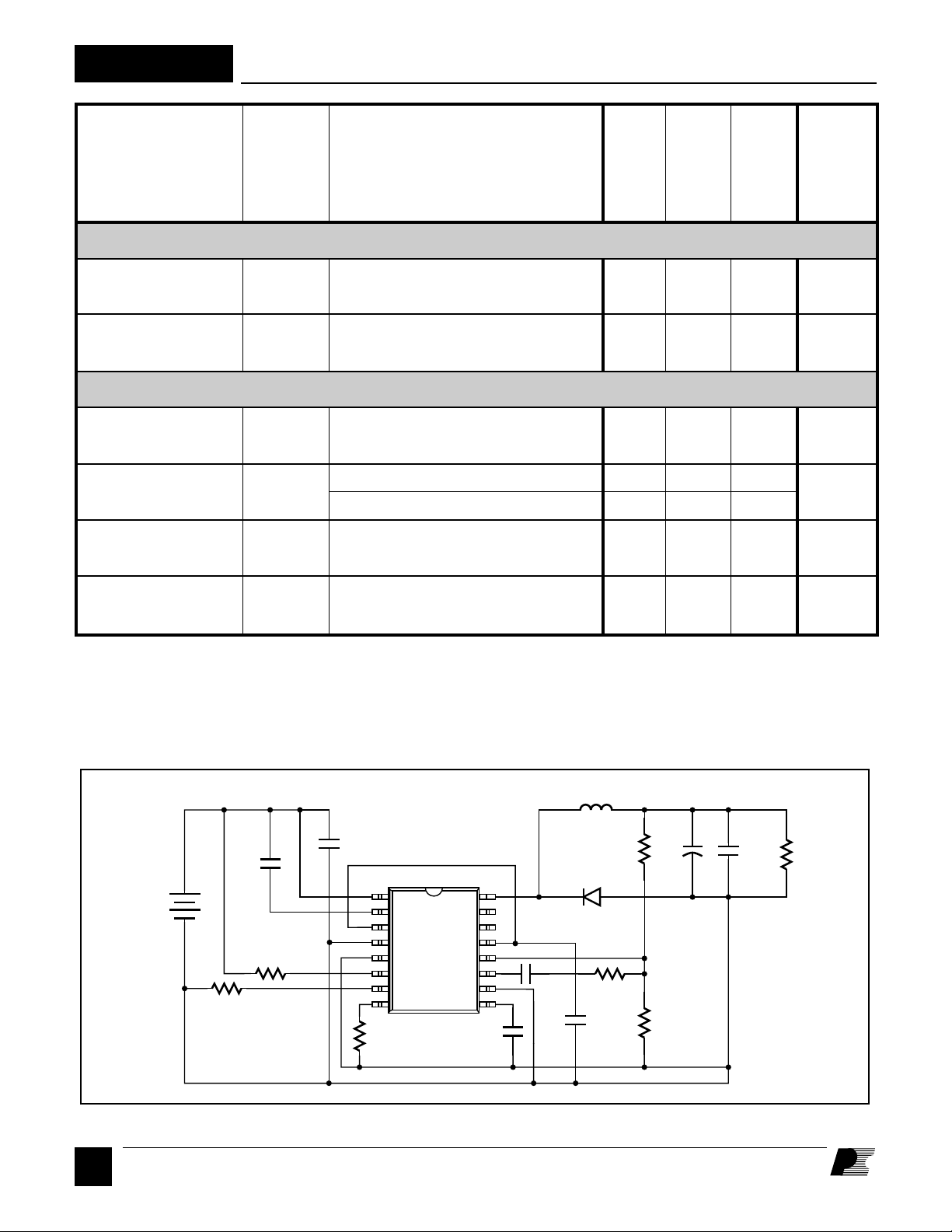
Figure 7. Switching Time Test Circuit.
D
10
1/96
C1
1
2
3
4
5
6
7
8
20.5 kΩ
U1
SMP402SC
16
15
14
13
12
11
10
9
120 pF
470 µH
75 kΩ
UF4002
1 nF
240 kΩ
100 nF
82 µF
24.9 kΩ
100 nF
152 Ω
PI-1456-042695
Page 11
SMP402
BREAKDOWN vs. TEMPERATURE
1.1
1.0
(Normalized to 25°C)
Breakdown Voltage (V)
0.9
-50 -25 0 25 50 75 100 125 150
Junction Temperature (°C)
C
100
80
vs. DRAIN VOLTAGE
OSS
PI-176B-051391
PI-1008-051093
f
vs. EXTERNAL CAPACITANCE
PWM
500
400
300
200
100
PWM Frequency (kHz)
0
100 200 400 500
0
300
External Capacitance (pF)
DRAIN CHARGE vs. DRAIN VOLTAGE
3.0
2.5
PI-1011-051793
PI-942-022293
60
40
20
Drain Capacitance (pF)
0
0 20 40 60 80
Drain Voltage (V)
Drain Charge (nC)
DRAIN CAPACITANCE ENERGY
60
50
40
30
Energy (nJ)
20
2.0
1.5
1.0
0.5
0
0 20 40 60 80
Drain Voltage (V)
PI-941-022293
10
0
0 20 40 60 80
Drain Voltage (V)
1/96
D
11
Page 12
SMP402
PACKAGE POWER DERATING
8
6
4
2
Power Dissipation (W)
0
0 25 50 75 100 125
Case Temperature (°C)
Tj = 120°C
PI-1013-052093
TRANSIENT THERMAL IMPEDANCE
100
10
1
Thermal Impedance (°C/W)
0.1
-4
10 10 10 10 1 10 100 1000
-1-2-3
Time (s)
PI-1012-051793
S16A Plastic SO-16 (W)
DIM inches mm
A .398-.413 10.10-10.50
B .050 BSC 1.27 BSC
C .014-.018 0.36-0.46
E .093-.104 2.35-2.65
F .004-.012 0.10-0.30
J .394-.418 10.01-10.62
L .009-.012 0.23-0.32
M .020-.040 0.51-1.02
N .291-.299 7.40-7.60
Notes:
1. Package dimensions conform to JEDEC
specification MS-013-AA for standard small outline
(SO) package, 16 leads, 7.50 mm (.300 inch) body
width (issue A, June 1985).
2. Controlling dimensions are in mm.
3. Dimensions are for the molded body and do not
include mold flash or protrusions. Mold flash or
protrusions shall not exceed .15 mm (.006 inch) on
any side.
4. Pin 1 side identified by chamfer on top edge of
the package body or indent on Pin 1 end.
16
1
(3)
A
9
(3)
N
8
J
L
E
C
B
F
0-8˚ TYP.
M
12
D
1/96
PI-1846-050196
Page 13

NOTES
SMP402
1/96
D
13
Page 14

SMP402
NOTES
14
D
1/96
Page 15

NOTES
SMP402
1/96
D
15
Page 16

SMP402
Power Integrations reserves the right to make changes to its products at any time to improve reliability or manufacturability.
Power Integrations does not assume any liability arising from the use of any device or circuit described herein, nor does it
convey any license under its patent rights or the rights of others.
PI Logo and
TOPSwitch
are registered trademarks of Power Integrations, Inc.
©Copyright 1994, Power Integrations, Inc. 477 N. Mathilda Avenue, Sunnyvale, CA 94086
WORLD HEADQUARTERS
Power Integrations, Inc.
477 N. Mathilda Avenue
Sunnyvale, CA 94086
USA
Main: 408•523•9200
Customer Service:
Phone: 408•523•9265
Fax: 408•523•9365
JAPAN
Power Integrations, K.K.
Keihin-Tatemono 1st Bldg.
12-20 Shin-Yokohama 2-Chome, Kohoku-ku,
Yokohama-shi, Kanagawa 222
Japan
Phone: 81•(0)•45•471•1021
Fax: 81•(0)•45•471•3717
D
16
1/96
AMERICAS
For Your Nearest Sales/Rep Office
Please Contact Customer Service
Phone: 408•523•9265
Fax: 408•523•9365
ASIA & OCEANIA
For Your Nearest Sales/Rep Office
Please Contact Customer Service
Phone: 408•523•9265
Fax: 408•523•9365
EUROPE & AFRICA
Power Integrations (Europe) Ltd.
Mountbatten House
Fairacres
Windsor SL4 4LE
United Kingdom
Phone: 44•(0)•1753•622•208
Fax: 44•(0)•1753•622•209
APPLICATIONS HOTLINE
World Wide 408•523•9260
APPLICATIONS FAX
Americas 408•523•9361
Europe/Africa
44•(0)•1753•622•209
Japan 81•(0)•45•471•3717
Asia/Oceania 408•523•9364
 Loading...