

Page 1

INTEGRATED CIRCUITS
DATA SH EET
SAA5281
Integrated Video input processor
and Teletext decoder (IVT1.8*)
Preliminary specification
Supersedes data of June 1994
File under Integrated Circuits, IC02
1996 Nov 04
Page 2
Philips Semiconductors Preliminary specification
Integrated Video input processor and
Teletext decoder (IVT1.8*)
FEATURES
• Complete Teletext and VPS decoding in a single
package
• Built-in 8K × 8 memory for up to 8 page storage
• Enhanced mode allows 7 Fastext pages and 8 pages of
TOP to be captured
• Ability to request only subtitle pages
• Acquisition and decoding of VPS data
• Data valid output available to indicate reception of
error-free VPS or packet 8/30/2 data
• Software and hardware compatible with SAA5246 and
SAA5248
• Meshing display within boxes
• Separate data checking algorithms and pointers for
each acquisition channel
• 24 : 18 Hamming checker
• Automatic packet 26 extension character processing
• Indication of Line 23 for external use
• 13.5 MHz clock output to drive external microcontroller
• Detection of Spanish transmissions to disable
flicker-stopper
• Compatible with Philips’ one-chip TV IC (TDA836X) for
scan-locking applications.
SAA5281
DESCRIPTION
The IVT1.8* is a single-chip Teletext decoder IC for
decoding 625-line based World System Teletext
transmissions. The device is based on IVT1.0VPS and has
reception facilities for the 5 MHz biphase VPS signal. It is
intended for use in video recorders, in particular to
implement the VPT facility (VCR programming via
Teletext). With suitable software both VPT standards
(EBU PDC System A and System B) can be
accommodated to allow operation from any European VPT
transmission. Automatic processing of packet 26
transmissions is also possible. No external memory is
required as an 8K × 8 DRAM is included on-chip for up to
8 page storage. An enhanced mode allows 7 Fastext
pages to be stored, with one chapter used to store
extension packets.
QUICK REFERENCE DATA
SYMBOL PARAMETER MIN. TYP. MAX. UNIT
V
DD
I
DD
V
sync
V
vid(p-p)
supply voltage 4.5 5.0 5.5 V
supply current − 75 150 mA
sync voltage amplitude 0.1 0.3 0.6 V
video input voltage amplitude
0.7 1.0 1.4 V
(peak-to-peak value)
f
T
xtal
amb
crystal frequency − 27 − MHz
operating ambient temperature −20 − +70 °C
ORDERING INFORMATION
PACKAGE
TYPE NUMBER
NAME DESCRIPTION VERSION
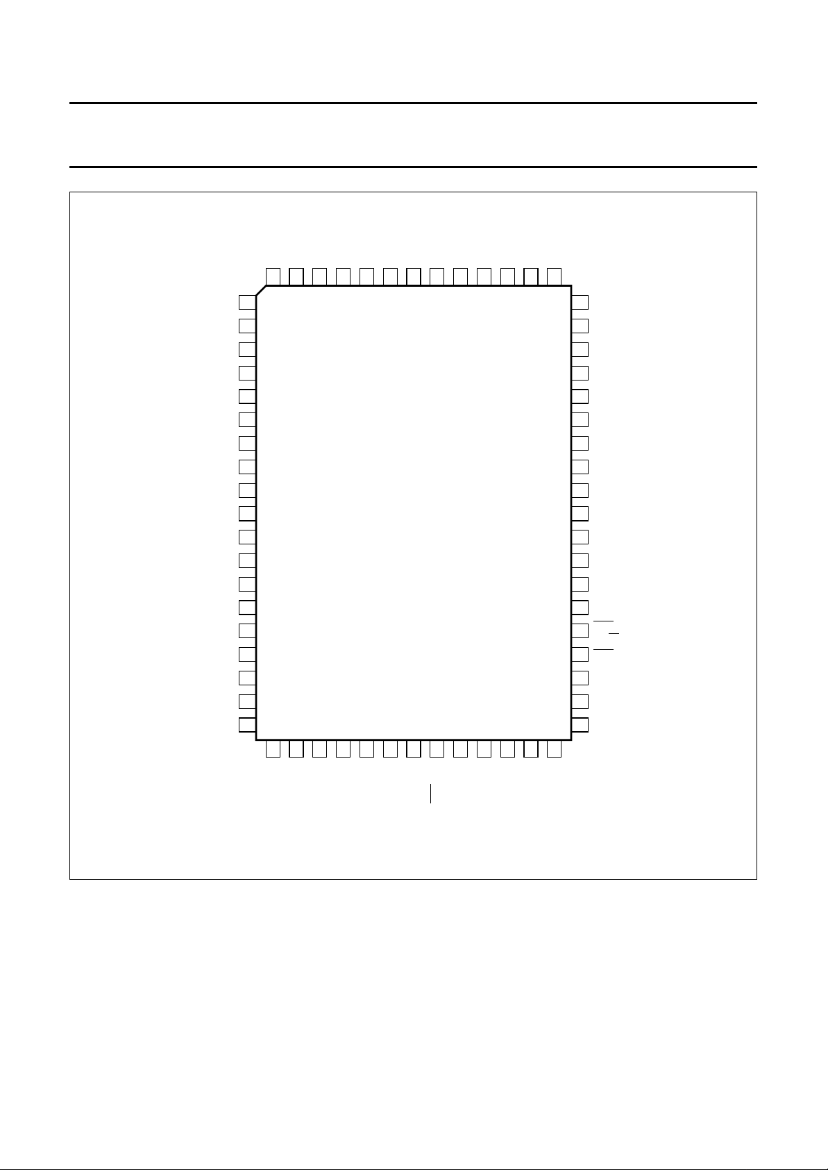
SAA5281P DIP48 plastic shrink dual in-line package; 32 leads (400 mil) SOT240-1
SAA5281ZP SDIP52 plastic shrink dual in-line package; 52 leads (600 mil) SOT247-1
SAA5281GP QFP64 plastic quad flat package; 64 leads
SOT319-2
(lead length 1.95 mm); body 14 × 20 × 2.8 mm
1996 Nov 04 2
Page 3
Philips Semiconductors Preliminary specification
Integrated Video input processor and
Teletext decoder (IVT1.8*)
BLOCK DIAGRAM
BLAN
handbook, full pagewidth
ODD/EVEN
(or DV)
V
DD1VDD2
110
POWER-ON
RESET
21
24 TO 18
HAMMING
DECODER
Y
22 19 20 18 15 16 17
RGBREF
COR
DISPLAY
RGB
PACKET 26
PROCESSING
ENGINE
DRAM
REFRESH
AND
TIMING
SAA5281
8K x 8
DRAM
MEMORY
INTERFACE
REF
IREF
AND DECODING
CONVERTER
DATA SLICER
REGENERATOR
6
ANALOG
9
REFERENCE
GENERATOR
V
SS1
TELETEXT
AQUISITION
SERIAL-TO
-PARALLEL
AND CLOCK
14 255
V
SS2
ANALOG
DIGITAL
CONVERTER
V
SS3
VPS
ACQUISITION
AND
DECODING
TELETEXT
OR
VPS CONTROL
TO
CVBS BLACK STTV/LFB
INPUT
CLAMP
AND SYNC
SEPARATOR
78 12 36 2 3
SAA5281
ANALOG
OUTPUT
BUFFER
2
I C-BUS
INTERFACE
TIMING
CHAIN
DISPLAY CLOCK
PHASE-LOCKED
LOOP
27 MHz
CLOCK
GENERATOR
CLK EN
OSCOUT
OSCIN
24
SDA
23
SCL
44
LINE 23
VCR/FFB
13
11
POL
CLK O/P
37
4
OSCGND
MBD783
Fig.1 Block diagram; pin numbers for DIP48 (SOT240-1).
1996 Nov 04 3
Page 4
Philips Semiconductors Preliminary specification
Integrated Video input processor and
SAA5281
Teletext decoder (IVT1.8*)
PINNING
SYMBOL
SOT240-1 SOT247-1 SOT319-2
V
DD1
1 52 11 +5 V supply 1
OSCOUT 2 1 13 27 MHz crystal oscillator output
OSCIN 3 2 14 27 MHz crystal oscillator input
OSCGND 4 3 15 0 V crystal oscillator ground
V
SS1
5 4 and 5 16 0 V ground
REF+ 6 6 18 positive reference voltage for ADC; this pin should be connected
BLACK 7 8 19 video black level storage input/output; this pin should be
CVBS 8 9 20 composite video input; a positive-going 1 V (peak-to-peak) input
IREF 9 10 21 reference current input, connected to ground via a 27 kΩ resistor
V
DD2
10 11 22 +5 V supply 2
POL 11 12 23 STTV/LFB/FFB polarity selection input
STTV/LFB 12 13 24 sync to TV output line flyback input; function controlled by an
VCR/FFB 13 14 27 PLL time constant switch/field input; function controlled by an
V
SS2
14 15 28 0 V ground; connected to V
R 15 16 30 dot rate character output of the RED colour information
G 16 17 32 dot rate character output of the GREEN colour information
B 17 18 33 dot rate character output of the BLUE colour information
RGBREF 18 19 34 input DC voltage to define the output high level on the RGB pins
BLAN 19 20 35 dot rate fast blanking output
COR 20 21 36 programmable output to provide contrast reduction of the TV
ODD/EVEN
21 22 37 in ODD/EVEN mode a 25 Hz output synchronized with the CVBS
(or DV)
Y 22 23 38 dot rate character output of teletext foreground colour information;
SCL 23 24 39 serial clock input for I
SDA 24 25 40 serial data port for the I
V
SS3
25 26 44 0 V ground
PIN
DESCRIPTION
to ground via a 100 nF capacitor
connected to ground via a 100 nF capacitor
is required, connected via a 100 nF capacitor
internal register bit (scan sync mode)
internal register bit (scan sync mode)
for normal operation
SS1
picture for mixed text and picture displays or when viewing
newsflash/subtitle pages;
open-drain output
input field sync pulses to produce a non-interlaced display by
adjustment of the vertical deflection currents; in DV mode a VPT
data valid signal is used to indicate reception of error-free VPS or
8/30 format 2 data
open-drain output
2
C-bus; it can still be driven HIGH during
power-down of the device
2
C-bus, open-drain output; it can still be
driven HIGH during power-down of the device
1996 Nov 04 4
Page 5

Philips Semiconductors Preliminary specification
Integrated Video input processor and
SAA5281
Teletext decoder (IVT1.8*)
SYMBOL
SOT240-1 SOT247-1 SOT319-2
i.c. 26 to 35,
38 to 43,
45 to 48
CLK EN 36 39 56 clock enable input to enable the clock output (CLP O/P pin 37);
CLK O/P 37 40 59 13.5 MHz clock output to drive an external microcontroller
LINE 23 44 47 4 output for indication of Line 23 for use with external circuitry
n.c. − 7, 33, 34 9, 10, 12,
PIN
27 to 32,
35 to 38,
41 to 46,
48 to 51
1to3,
5to8,
45 to 53,
55, 61,
63 to 64
17, 25, 26,
29, 31,
41 to 43,
54, 57, 58,
60, 62
DESCRIPTION
internally connected; normally open-circuit
internal pull-down normally disables clock
not connected; normally open-circuit
1996 Nov 04 5
Page 6
Philips Semiconductors Preliminary specification
Integrated Video input processor and
Teletext decoder (IVT1.8*)
handbook, halfpage
V
DD1
OSCOUT
OSCIN
OSCGND
V
SS1
REF+
BLACK
CVBS
IREF
V
DD2
POL
STTV/LFB
VCR/FFB
V
SS2
RGBREF
BLAN
COR
ODD/EVEN
(or DV)
SCL
SDA
MBD784
48 i.c.
i.c.
47
i.c.
46
45
i.c.
LINE 23
44
i.c.
43
42
i.c.
i.c.
41
i.c.
40
i.c.
39
38
i.c.
CLK O/P
37
36
CLK EN
i.c.
35
i.c.
34
33
i.c.
32
i.c.
31
i.c.
i.c.
30
29
i.c.
28
i.c.
i.c.
27
i.c.
26
V
25
SS3
1
2
3
4
5
6
7
8
9
10
11
12
SAA5281
13
14
15
R
G
16
17
B
18
19
20
21
22
Y
23
24
handbook, halfpage
OSCOUT
OSCGND
STTV/LFB
VCR/FFB
ODD/EVEN
OSCIN
V
SS1
V
SS1
REF+
n.c.
BLACK
CVBS
IREF
V
DD2
POL
V
SS2
RGBREF
BLAN
COR
(or DV)
SCL
SDA
V
SS3
SAA5281
1
2
3
4
5
6
7
8
9
10
11
12
SAA5281
13
14
15
R
16
G
17
B
18
19
20
21
22
Y
23
24
25
26
MBD785
52
51
50
49
48
47
46
45
44
43
42
41
40
39
38
37
36
35
34
33
32
31
30
29
28
27
V
DD1
i.c.
i.c.
i.c.
i.c.
LINE 23
i.c.
i.c.
i.c.
i.c.
i.c.
i.c.
CLK O/P
CLK EN
i.c.
i.c.
i.c.
i.c.
n.c.
n.c.
i.c.
i.c.
i.c.
i.c.
i.c.
i.c.
Fig.2 Pin configuration; SOT240-1 (DIP48).
1996 Nov 04 6
Fig.3 Pin configuration; SOT247-1 (SDIP52).
Page 7
Philips Semiconductors Preliminary specification
Integrated Video input processor and
Teletext decoder (IVT1.8*)
handbook, full pagewidth
i.c.
n.c.
i.c.
i.c.
64
63
62
1
i.c.
i.c.
2
i.c.
3
LINE 23
OSCOUT
OSCGND
4
i.c.
5
i.c.
6
7
i.c.
i.c.
8
n.c.
9
10
n.c.
V
11
DD1
n.c.
12
13
OSCIN
14
15
V
16
SS1
17
n.c.
18
REF+
19
BLACK B
n.c.
61
60
CLK O/P
n.c.
59
58
SAA5281
n.c.
57
i.c.
CLK EN
56
55
n.c.
54
i.c.
53
i.c.
52
51
i.c.
50
i.c.
i.c.
49
i.c.
48
47
i.c.
46
i.c.
i.c.
45
V
44
n.c.
43
42
n.c.
41
n.c.
40
SDA
SCL
39
38
Y
ODD/EVEN
37
(or DV)
36
COR
BLAN
35
34
RGBREF
33
SAA5281
SS3
20
21
22
23
24
25
CVBS
IREF
DD2
V
POL
n.c.
STTV/LFB
Fig.4 Pin configuration; SOT319-2 (QFP64).
1996 Nov 04 7
26
n.c.
27
28
SS2
V
VCR/FFB
29
n.c.
30
31
32
n.c.
G
MBH665
R
Page 8
Philips Semiconductors Preliminary specification
Integrated Video input processor and
Teletext decoder (IVT1.8*)
QUALITY AND RELIABILITY
This device will meet Philips Semiconductors General Quality Specification for Business group
Circuits SNW-FQ-611-Part E”
Group A
Table 1 Acceptance tests per lot
TEST REQUIREMENTS
Mechanical cumulative target: <100 ppm
Electrical cumulative target: <100 ppm
Group B
Table 2 Processability tests (by package family)
TEST REQUIREMENTS
Solderability <7% LTPD
Mechanical <15% LTPD
Solder heat resistance <15% LTPD
. The principal requirements are shown in Tables 1 to 4.
(1)
(1)
SAA5281
“Consumer Integrated
Group C
Table 3 Reliability tests (by process family)
TEST CONDITIONS REQUIREMENTS
Operational life 168 hours at Tj= 150 °C <1500 FPM; equivalent to
<100 FITS at Tj=70°C
Humidity life temperature, humidity, bias
<2000 FPM
1000 hours, 85 °C, 85% RH
(or equivalent test)
Temperature cycling performance T
stg(min)
to T
stg(max)
<2000 FPM
Table 4 Reliability tests (by device type)
TEST CONDITIONS REQUIREMENTS
ESD and latch-up ESD Human body model
<15% LTPD
2000 V, 100 pF, 1.5 kΩ
ESD Machine model
<15% LTPD
200 V, 200 pF, 0 Ω
latch-up 100 mA, 1.5 × V
DD
<15% LTPD
(absolute maximum)
Notes to Tables 1 to 4
1. ppm = fraction of defective devices, in parts per million.
LTPD = Lot Tolerance Percent Defective.
FPM = fraction of devices failing at test condition, in Failures Per Million.
FITS = Failures In Time Standard.
(1)
(1)
1996 Nov 04 8
Page 9
Philips Semiconductors Preliminary specification
Integrated Video input processor and
SAA5281
Teletext decoder (IVT1.8*)
LIMITING VALUES
In accordance with Absolute Maximum Rating System (IEC 134).
SYMBOL PARAMETER MIN. MAX. UNIT
V
DD
V
I
V
O
I
O
I
IOK
T
amb
CHARACTERISTICS
= 5 V ±10%; T
V
DD
SYMBOL PARAMETER CONDITIONS MIN. TYP. MAX. UNIT
Supplies
V
DD
I
DDtot
Inputs
supply voltage (all supplies) −0.3 +6.5 V
input voltage (any input) −0.3 VDD+ 0.5 V
output voltage (any output) −0.3 VDD+ 0.5 V
output current (each output) −±10 mA
DC input or output diode current −±20 mA
operating ambient temperature −20 +70 °C
= −20 to +70 °C; pin numbers refer DIP48 package; unless otherwise specified.
amb
supply voltage 4.5 5.0 5.5 V
total supply current − 75 150 mA
CVBS
V
sync
V
burst(p-p)
sync voltage amplitude 0.1 0.3 0.6 V
colour burst amplitude
0.0 0.3 4.0 V
(peak-to-peak value)
t
d(sync)
delay from CVBS to TCS
−150 0 +150 ns
output from STTV buffer
(nominal video, average of
leading/trailing edge)
∆t
d(sync)
change in sync delay between
0 − 25 ns
all black and all white video
input at nominal levels
V
vid(p-p)
video input voltage amplitude
0.7 1.0 1.4 V
(peak-to-peak value)
V
dat(text)
teletext data voltage amplitude 0.29 0.46 0.71 V
∆f/f display PLL capture range ±7 −−%
Z
source
V
I
source impedance −−250 Ω
input switching voltage level of
1.7 2.0 2.3 V
sync separator
Z
I
C
I
input impedance 2.5 5.0 − kΩ
input capacitance −−10 pF
IREF
R
gnd
V
i
resistor to ground − 27 − kΩ
input voltage − 0.5V
DD
− V
1996 Nov 04 9
Page 10
Philips Semiconductors Preliminary specification
Integrated Video input processor and
SAA5281
Teletext decoder (IVT1.8*)
SYMBOL PARAMETER CONDITIONS MIN. TYP. MAX. UNIT
POL
V
IL
V
IH
I
LI
C
I
LFB
V
IL
V
IH
I
LI
I
Imax
t
dLFB
VCR/FFB
V
IL
V
IH
I
LI
I
Imax
RGBREF
V
IL
I
LI
SCL
V
IL
V
IH
I
LI
C
I
f
clk
t
r
t
f
Inputs/outputs
LOW level input voltage −0.3 − +0.8 V
HIGH level input voltage 2.0 − VDD+ 0.5 V
input leakage current VI= 0 to V
DD
−10 − +10 µA
input capacitance −−10 pF
LOW level input voltage −0.3 − tbf V
HIGH level input voltage tbf − VDD+ 0.5 V
input leakage current VI= 0 to V
DD
−10 − +10 µA
maximum input current note 1 −1 − +1 mA
delay between LFB front edge
− 250 − ns
and input video line sync
LOW level input voltage −0.3 − +0.8 V
HIGH level input voltage 2.0 − VDD+ 0.5 V
input leakage current VI= 0 to V
DD
−10 − +10 µA
maximum input current note 1 −1 − +1 mA
LOW level input voltage −0.3 − V
input leakage current VI= 0 to V
DD
−10 − +10 µA
DD
V
LOW level input voltage −0.3 − +1.5 V
HIGH level input voltage 3.0 − VDD+ 0.5 V
input leakage current VI= 0 to V
DD
−10 − +10 µA
input capacitance −−10 pF
clock frequency 0 − 100 kHz
input rise time between 10% and 90% −−2µs
input fall time between 90% and 10% −−2µs
C
RYSTAL OSCILLATOR (OSCIN; OSCOUT)
V
osc(p-p)
oscillator voltage amplitude
(peak-to-peak value)
G
v
G
m
C
I
C
fb
small signal voltage gain − 1.0 −
mutual conductance 5.0 −−mS
input capacitance −−10 pF
feedback capacitance − 1 − pF
1996 Nov 04 10
− 1.0 − V
Page 11
Philips Semiconductors Preliminary specification
Integrated Video input processor and
SAA5281
Teletext decoder (IVT1.8*)
SYMBOL PARAMETER CONDITIONS MIN. TYP. MAX. UNIT
BLACK
C
black
V
black
I
LI
SDA (OPEN-DRAIN INPUT/OUTPUT)
V
IL
V
IH
V
OL
I
LI
C
I
C
L
t
r
t
f
t
f
Outputs
storage capacitor to ground − 100 − nF
black level voltage for nominal
1.8 2.15 2.5 V
sync amplitude
input leakage current VI= 0 to V
DD
−10 − +10 µA
LOW level input voltage −0.3 − +1.5 V
HIGH level input voltage 3.0 − VDD+ 0.5 V
LOW level output voltage IOL= 3 mA 0 − 0.5 V
input leakage current VI= 0 to V
DD
−10 − +10 µA
input capacitance −−10 pF
load capacitance −−400 pF
input rise time between 10% and 90% −−2µs
input fall time between 90% and 10% −−2µs
output fall time between 3 V and 1 V −−200 ns
STTV
G
sttv
gain of STTV relative to video
0.9 1.0 1.1
input
V
∆V
tcs
tcs
TCS voltage amplitude 0.2 0.3 0.45 V
DC shift between TCS output
−−0.15 V
and nominal video output
I
O
C
L
output drive current −−3.0 mA
load capacitance −−100 pF
R, G AND B
V
OL
V
OH
LOW level output voltage IOL= 2 mA 0 − 0.2 V
HIGH level output voltage IOH= −1.6 mA;
V
RGBREF
< VDD− 2V;
V
RGBREF
− 0.25
V
RGBREFVRGBREF
+ 0.5
note 2
| output impedance −−200 Ω
|Z
o
C
L
t
r
t
f
load capacitance −−50 pF
output rise time between 10% and 90% −−20 ns
output fall time between 90% and 10% −−20 ns
BLAN
V
OL
V
OH
C
L
t
r
t
f
LOW level output voltage IOL= 1.6 mA 0 − 0.4 V
HIGH level output voltage IOH= − 0.2 mA 1.1 −−V
I
=0mA −−2.8 V
OH
load capacitance −−50 pF
output rise time between 10% and 90% −−20 ns
output fall time between 90% and 10% −−20 ns
V
1996 Nov 04 11
Page 12
Philips Semiconductors Preliminary specification
Integrated Video input processor and
SAA5281
Teletext decoder (IVT1.8*)
SYMBOL PARAMETER CONDITIONS MIN. TYP. MAX. UNIT
ODD/EVEN OR DV
V
OL
V
OH
C
L
t
r
t
f
COR AND Y(OPEN-DRAIN OUTPUTS)
V
OH
V
OL
C
L
t
f
I
LO
t
skew
2
C-bus timing (see Fig.5)
I
t
LOW
t
HIGH
t
SU;DAT
t
HD;DAT
t
SU;STO
t
BUF
t
HD;STA
t
SU;STA
LOW level output voltage IOL= 1.6 mA 0 − 0.4 V
HIGH level output voltage IOH= −1.6 mA VDD− 0.4 − V
DD
V
load capacitance −−120 pF
output rise time between 0.6 V and
−−50 ns
2.2 V
output fall time between 0.6 V and
−−50 ns
2.2 V
HIGH level pull-up output
−−VDDV
voltage
LOW level output voltage IOL= 2 mA 0 − 0.4 V
= 5 mA 0 − 1.0 V
I
OL
load capacitance −−25 pF
output fall time load resistor of 1.2 kΩ
−−50 ns
to VDD; measured
between VDD− 0.5 V
and 1.5 V
output leakage current VI= 0 to V
skew delay between display
DD
−10 − +10 µA
−−20 ns
outputs R, G, B, COR, Y and
BLAN
SCL clock LOW time 4.0 −−µs
SCL clock HIGH time 4.0 −−µs
data set-up time 250 −−ns
data hold time 170 −−ns
set-up time from clock HIGH
4.0 −−µs
to STOP
ST ART set-up time following a
4.0 −−µs
STOP
START hold time 4.0 −−µs
ST ART set-up time following a
4.0 −−µs
clock LOW-to-HIGH transition
Notes
1. This current is the maximum allowed into the inputs when line and field flyback signals are connected to these inputs.
Series current limiting resistors must be used to limit the input currents to ±1 mA.
2. Voltage level VOH for R, G and B outputs is taken to be the mean value during the output HIGH time. If higher R, G
and B voltage VOH levels are required RGBREF voltage level may be raised and a pull-up resistor used at each of
these pins provided current specification (IOL) is not exceeded.
1996 Nov 04 12
Page 13
Philips Semiconductors Preliminary specification
Integrated Video input processor and
Teletext decoder (IVT1.8*)
handbook, full pagewidth
SDA
t
LOW
SCL
SDA
MBC764
t
BUF
t
HD;STA
t
r
t
SU;STA
t
HD;DAT
t
HIGH
SAA5281
t
f
t
SU;DAT
t
SU;STO
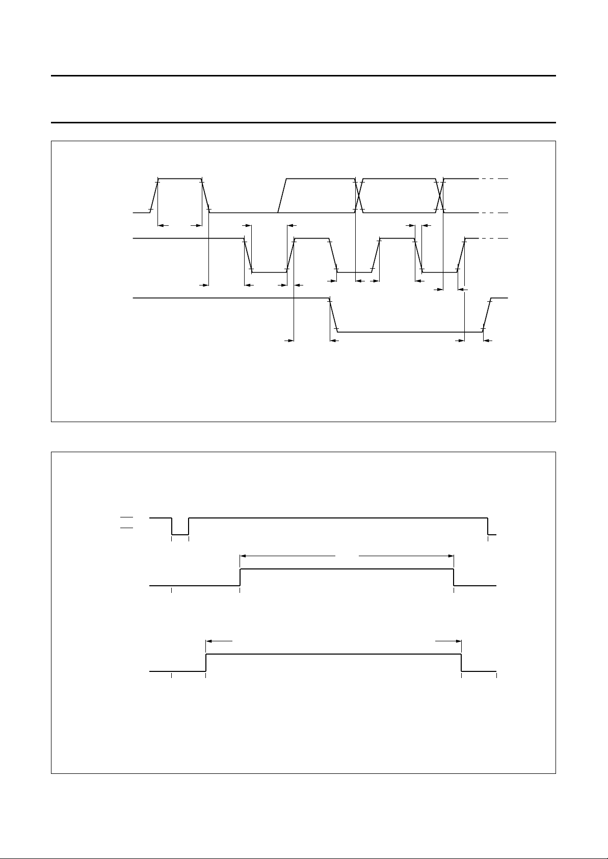
TIMING CHAIN
handbook, full pagewidth
LSP
(TCS)
R, G, B, Y
(1)
R, G, B, Y
(1)
0 4.66
0
0
Fig.5 I2C-bus timing.
40 µs
display period
16.67
lines 42 to 291 inclusive (and 355 to 604 inclusive interlaced)
display period
41
56.67 µs
64 µs
291
line numbers
MLA662 - 1
312
(1) Also BLAN in character and box blanking.
Fig.6 Display output timing (a) line rate (b) field rate.
1996 Nov 04 13
Page 14
Philips Semiconductors Preliminary specification
Integrated Video input processor and
Teletext decoder (IVT1.8*)
64 µs
64 µs
64 µs
59.33
SAA5281
MLA037 - 2
0 4.66
32 34.33
0 2.33
handbook, full pagewidth
27.33 32
0
1 2 3456 7
625
(312)
624
(311)
623
(310)
622
(309)
621
(308)
309 310 311 312 313 314 (1) 315 (2) 316 (3) 317 (4) 318 (5) 319 (6) 320 (7)
Fig.7 Composite sync waveforms.
308 309 310 311 312 1 2 3 4 5 6 7
LSP
(Line Sync Pulse)
EP
(Equalizing Pulse)
BP
(Broad Pulse)
1996 Nov 04 14
TCS interlaced
TCS interlaced
TCS non-interlaced
LSP, EP and BP are combined to give TCS as shown. All timings are measured from falling edge of LSP.
Line numbers placed in the middle of the line.
Equivalent count numbers in brackets.
Page 15
Philips Semiconductors Preliminary specification
Integrated Video input processor and
Teletext decoder (IVT1.8*)
7
SAA5281
MLA416 - 2
320 (7)
FIRST FIELD START (EVEN)
625
(312) 1 2 3 4 5 6
(311)(310)(308) (309)
621 622 623 624
TCS interlaced
2 µs
ODD / EVEN output
(normal sync mode)
48 µs
(1)
30 µs
ODD / EVEN output
(normal sync mode
when VCS to SCS
mode active)
ODD / EVEN output
SECOND FIELD START (ODD)
314 (1) 315 (2) 316 (3) 317 (4) 318 (5) 319 (6)
311
309 310 312 313
(slave sync mode)
TCS interlaced
16 µs
2 µs
ODD / EVEN output
(normal sync mode
ODD / EVEN output
(normal sync mode)
when VCS to SCS
(1)
mode active)
ODD / EVEN output
30 µs
(slave sync mode)
handbook, full pagewidth
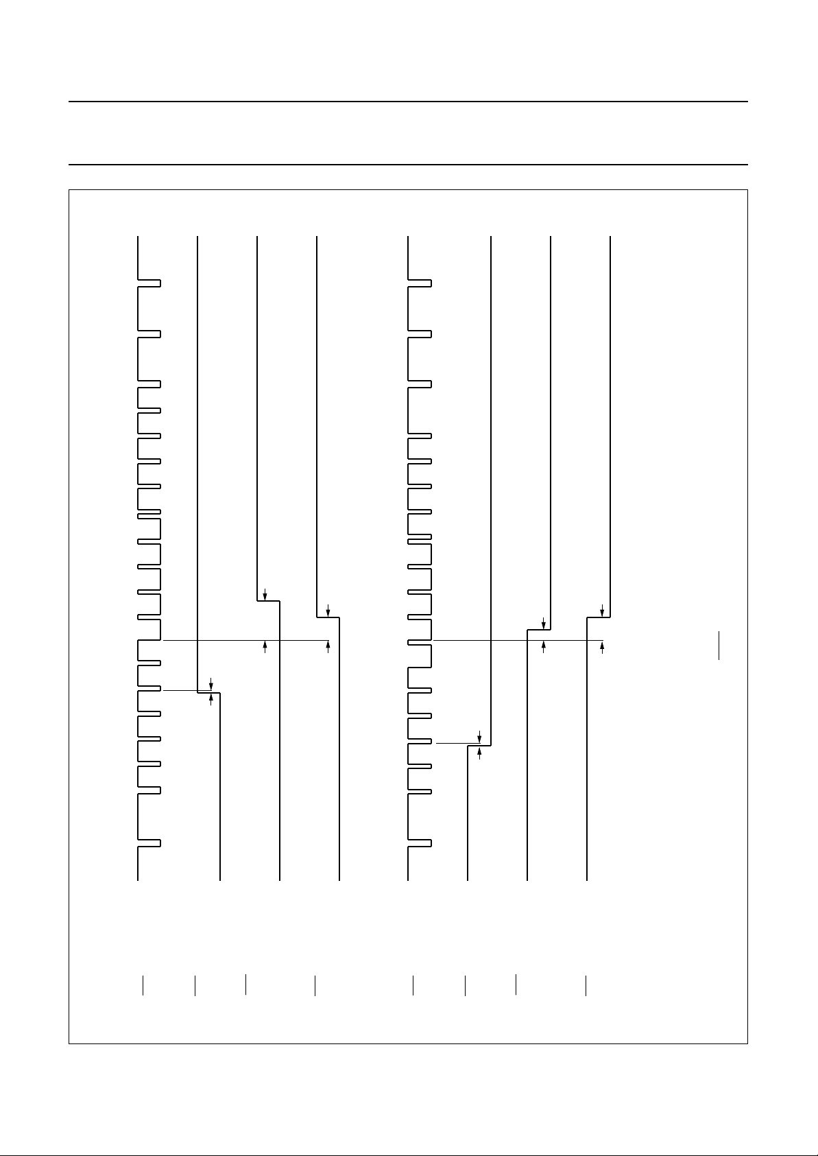
Fig.8 ODD/EVEN timing.
1996 Nov 04 15
Line numbers placed in the middle of the line.
Equivalent count numbers in brackets.
(1) Or 62 µs if Register 1 D2.D1.D0 equals 1 1 1.
Page 16

Philips Semiconductors Preliminary specification
Integrated Video input processor and
SAA5281
Teletext decoder (IVT1.8*)
ON-CHIP MEMORY
Page memory organization
The organization of the page memory is illustrated by Fig.9. The IVT1.8* provides an additional row as compared with
first generation decoders; this brings the display format up to 40 characters by 25 rows. Rows 0 to 23 form the teletext
page; row 24 is the extra row available for software generated status messages and FLOF/FASTEXT prompt
information.
handbook, full pagewidth
7 characters
for status
71
fixed character
written by IVT hardware:
alphanumerics white for normal;
alphanumerics green when looking
for display page
24 characters from page header
rolling when display page looked for
8 characters
always rolling
(time)
824
ROW
0
1
2
3
4
MAIN PAGE DISPLAY AREA
PACKET X / 22
PACKET X / 23
PACKET X / 24 STORED HERE IF R0D7 = 1
10 14
10 bytes for
received
page information
if enabled 14 bytes reserved in
chapter 5 for VPS data
Fig.9 Basic page memory organization.
REMARK TO Fig.9
Row 0
Row 0 is for the page header. The first seven characters
(0 to 6) are free for status messages. Character 8 is an
alphanumeric white or green control character, written
automatically by IVT1.8* to give a green rolling header
when a page is being looked for. The last eight characters
are for rolling time.
5
to
20
21
22
23
24
25
MBD789
Row 25
The first 10 bytes of row 25 contain control data relating to
the received page as shown in Table 5. The remaining
14 bytes are free for use by the microcomputer.
1996 Nov 04 16
Page 17

Philips Semiconductors Preliminary specification
Integrated Video input processor and
SAA5281
Teletext decoder (IVT1.8*)
Table 5 Row 25 received control data format
ROW 25
D0 PU0 PT0 MU0 MT0 HU0 HT0 C7 C11 MAG0 0
D1 PU1 PT1 MU1 MT1 HU1 HT1 C8 C12 MAG1 0
D2 PU2 PT2 MU2 MT2 HU2 C5 C9 C13 MAG2 0
D3 PU3 PT3 MU3 C4 HU3 C6 C10 C14 0 0
D4 HAM.ER HAM.ER HAM.ER HAM.ER HAM.ER HAM.ER HAM.ER HAM.ER
D5 0 0 0 0 0 0 0 0 0 PBLF
D60000000000
D70000000000
Column 0 1 2 3 4 5 6 7 8 9
Table 6 Page number and sub-code for Table 5
BIT NAME DESCRIPTION
Page number
MAG magazine
PU page units
PT page tens
PBLF page being looked for
FOUND LOW for page has been found
HAM.ER Hamming error in corresponding byte
FOUND 0
Page sub-code
MU minutes units
MT minutes tens
HU hours units
HT hours tens
C4 to C14 transmitted control bits
1996 Nov 04 17
Page 18

Philips Semiconductors Preliminary specification
Integrated Video input processor and
SAA5281
Teletext decoder (IVT1.8*)
Extension packet memory organization
When in normal extension packet enabled mode the rows of information are organized as illustrated in Fig.10.
Row 23 of the extension page, as shown in Fig.10, contains packet 8/30. Packet 8/30 is mapped into the IVT1.8* memory
as follows:
8 / 30 / 0 and 8 / 30 / 1 to Chapter 4 Row 23
8 / 30 / 2 and 8 / 30 / 3 to Chapter 5 Row 23
8 / 30 / 4 to 8 / 30 / 15 to Chapter 6 Row 23.
handbook, full pagewidth
PACKETS X/26/0 to X/26/14
PACKET X/28/2
PACKETS X/27/0 to X/27/1
PACKETS X/27/4 to X/27/5
PACKET X/24 IF R0D7 = 0
PACKET X/25
PACKET X/28/0
PACKET 8/30
PACKET X/28/1
RESERVED
(1)
ROW
0
to
14
15
16
17
18
19
20
21
22
23
24
25
(1) Row 25 reserved for VPS data in Chapter 5.
Fig.10 Organization of the extension memory.
1996 Nov 04 18
MBD791
Page 19

Philips Semiconductors Preliminary specification
Integrated Video input processor and
SAA5281
Teletext decoder (IVT1.8*)
ENHANCED MODE
In enhanced mode, the number of extension packets captured is reduced to the minimum required for FASTEXT
operation. The first seven chapters can then be used for storage, using the system of pointers. The arrangement of
extension packets is shown in Fig.11.
When in enhanced mode and extension packets are disabled, normal 8-page mode is in operation, but the X/26 engine
is enabled (unlike normal 8-page mode).
handbook, halfpage
CHAPTER 0 PACKET 24
CHAPTER 0 PACKETS 27 / 0
CHAPTER 1 PACKET 24
CHAPTER 1 PACKETS 27 / 0
CHAPTER 2 PACKET 24
CHAPTER 2 PACKETS 27 / 0
CHAPTER 3 PACKET 24
CHAPTER 3 PACKETS 27 / 0
CHAPTER 4 PACKET 24
CHAPTER 4 PACKETS 27 / 0
CHAPTER 5 PACKET 24
CHAPTER 5 PACKETS 27 / 0
CHAPTER 6 PACKET 24
CHAPTER 6 PACKETS 27 / 0
not used
not used
PACKETS 8 / 30 / 0,1
PACKETS 8 / 30 / 2,3
PACKETS 8 / 30 / 4 to 15
not used
ROW
0
1
2
3
4
5
6
7
8
9
10
11
12
13
14
15
16
17
18
19 to 24
MBD788
Fig.11 Organization of the extension memory in enhanced mode.
1996 Nov 04 19
Page 20

Philips Semiconductors Preliminary specification
Integrated Video input processor and
Teletext decoder (IVT1.8*)
VPT data memory organization
To simplify the software for dual-standard VPT decoders,
the VPS data from line 16 is stored in row 25 of Chapter 5
of the page memory, and is aligned to match the
packet 8/30 format 2 data as far as possible. The 8/30
format 2 packet is Hamming coded and by setting the
appropriate register control bit the data is stored after
hardware Hamming correction. There are 4 data bits
stored in each column address of memory with an
additional Hamming error bit. The data equivalent to the
VPS signal is found in columns 12 to 19.
Although the VPS data is not Hamming protected, it is
stored with 4 data bits per column address in the same
way with an additional biphase error bit. The extra space
in Row 25 is allocated to two more Line 16 words.
SAA5281
They are Word 15 (reserved) and Word 4 (Program
Source Identification, ASCII sequential) which may be
useful for future applications. Details of the memory
organization are shown in Fig.12.
2
The stored data can be read from memory via the I
in the normal way. Multiple reception/majority error
correction of the VPS data is the responsibility of the
control software, the device simply stores the data as
transmitted after biphase decoding.
As both VPS and 8/30/2 signals are stored in separate
memory locations, it is possible to deal with future
situations where both System A and System B
transmissions may be present on the same TV channel,
the defaults and level of service chosen by the control
software.
C-bus
handbook, full pagewidth
column
8/30/2
VPS
column
8/30/2
VPS
0
20
21345678910 11 12 13 14 15 16 17 18 19
b13 b14 b15 b16 b17 b18 b19 b20 b21 b22 b23 b24 b25initial pageD
received page information
2221 23 24 25 26 27 28 29 30 11 12 13 14 15 16 17 18 19
B4
B5
B11 B12 B13 B14 B15
status display
MBD787
Fig.12 Detailed memory organization.
1996 Nov 04 20
Page 21

Philips Semiconductors Preliminary specification
Integrated Video input processor and
Teletext decoder (IVT1.8*)
SELECT
VCR MODE R11/R11B
ODD/EVEN
DISABLE
TCS ON T1 T0
CBB SLAVE
SYNC
DEW/ FULL
FIELD
A2 A1 A0
HEADER
ONLY
BOX ON 0
to 23
BOX ON 24 BOX ON 1
SINGLE/
DOUBLE
HEIGHT
VCS
SIGNAL
TEXT
SIGNAL
ROM
VER R0
R1
SAA5281
QUALITY
AUTO
DISPLAY
QUALITY
DISABLE
PKT X/26
HAM
CHECK
ENABLE
PKT X/24
24:18
DISABLE
AUTO
D7 D6 D5 D4 D3 D2 D1 D0
REGISTER
NAME No.
ENABLE
HDR ROLL
ODD/EVEN
PLL
ACQ CCT A1 ACQ CCT A0 0 SC2 SC1 SC0
7 + P/ 8-BIT ACQ ON/OFF EXT PKT
BANK
2 HAM CHECK
SELECT A2
27, 8/30
5 BKGND OUT BKGND IN COR OUT COR IN TEXT OUT TEXT IN PON OUT PON IN
6 BKGND OUT BKGND IN COR OUT COR IN TEXT OUT TEXT IN PON OUT PON IN
HALF
TOP/BTM
REVEAL ON
CURSOR ON CONCEAL/
BTM/TOP
ROM VER R4 ROM VER R3 ROM VER R2 ROM VER
625/525
SYNC
VPS ENABLE POINTS
MESHING
ENABLE
CURSOR
FREEZE/
DEVICE
IDENT
MODE
Mode 1 VCS TO SCS
Register maps
IVT1.8* mode registers R0 to R13 are shown in Table 7. R0 to R10, R12 and R13 are WRITE only; R11 is READ/WRITE, R11B is read only.
Register map (R3), for page requests, is shown in detail in Table 11.
Table 7 Register map (notes 1 to 4)
1996 Nov 04 21
Advanced control 0 X/24 POS FREE RUN
Page request
address
Page request data 3 −−−PRD4 PRD3 PRD2 PRD1 PRD0
Display chapter 4 −−−−FREEZE
Display control
(normal)
Display control
(newsflash /subtitle)
Display mode 7 STATUS
Active chapter 8 −−−VPS ENABLE CLEAR MEM A2 A1 A0
Cursor row 9 −−−R4 R3 R2 R1 R0
Cursor column 10 −−C5 C4 C3 C2 C1 C0
Cursor data 11 D7 D6 D5 D4 D3 D2 D1 D0
Device status 11B
Advanced control 2A 12 H3 H2 H1 H0 S3 S2 S1 S0
Advanced control 2B 13 ENHANC
Page 22

Philips Semiconductors Preliminary specification
Integrated Video input processor and
SAA5281
Teletext decoder (IVT1.8*)
Notes to Table 7
1. The dash (−) indicates these bits are inactive and must be written to logic 0 for future compatibility.
2. Certain registers are auto-incremented following an I2C-bus transmission byte. These are Register R0 to R3,
R4 to R7 and R8 to R12 or R13.
3. All bits in Registers R0 to R13 are cleared to logic 0 on power-up except bits D0 and D1 of Registers R1, R5 and R6
which are set to logic 1.
4. All memory is cleared to space (00100000) on power-up, except Row 0 Column 7 Chapter 0, which is alpha white
(00000111) as the acquisition circuit is enabled but all pages are on hold.
Table 8 Register description
REGISTER BIT D0 TO D7 FUNCTION
R0 AVANCED CONTROL - auto-increments to Register 1
R11/R11B SELECT Selects reading of R11 if LOW or R11B if HIGH.
VCR MODE If logic 1 selects short time constant mode of PLL.
DISABLE
CBB SLAVE SYNC When set will modify internal slave sync timing to allow connection to sandcastle of
DISABLE HDR ROLL Stops the display update of rolling time and green rolling header during page
AUTO
FREE RUN PLL Will force the display PLL to free run at 6 MHz when logic 1.
X/24 POS Automatic display of FASTEXT prompt row when logic 1. Will also cause Row 24
ODD/EVEN Forces ODD/EVEN output LOW when logic 1 (see Table 9).
Philips one-chip TV IC (TDA8362).
requests when logic 1. Time updates on page reception only.
ODD/EVEN If logic 1 then ODD/EVEN output only active when no TV picture displayed
(see Table 9).
data transmitted by packet 26 to be written to display, rather than extension
memory.
R1 MODE - auto-increments to Register 2
T0, T1 Interlace/non-interlace 312/313 line control (see Table 10).
TCS ON Text composite sync or direct sync select (see Table 10 for FFB mode selection).
DEW/FULL FIELD Field-flyback or full-channel mode.
EXT PKT ENABLE Enables reception and storage of extension packets when logic 1.
ON/OFF Acquisition circuits turned off when logic 1.
ACQ
7 + P/8-BIT 7 bits with parity checking or 8-bit mode.
VCS TO SCS Connects VCS from video sync separator to display field sync detector to enable
stable display of 60 Hz status messages when logic 1.
R2 PAGE REQUEST ADDRESS - auto-increments to Register 3
SC0 to SC2 Start column for page request data (see Table 11).
0 Must be logic 0 for normal operation.
ACQ CCT A0, A1 Selects one of four acquisition circuits.
BANK SELECT A2 Selects bank of four pages being addressed for acquisition.
HAM CHECK 27, 8/30 8/4 Hamming check packet 27 and 8/30 data.
R3 PAGE REQUEST DATA - does not auto-increment
PRD0 to PRD4 See Table 11.
1996 Nov 04 22
Page 23

Philips Semiconductors Preliminary specification
Integrated Video input processor and
Teletext decoder (IVT1.8*)
REGISTER BIT D0 TO D7 FUNCTION
R4 DISPLAY CHAPTER - auto-increments to Register 5
A0 to A2 Selects one of 8 display chapters.
FREEZE HEADER ONLY Freezes the rolling header, but (unlike R0D4) allows the time to roll.
R5 NORMAL DISPLAY CONTROL - auto-increments to Register 6
R6 NEWSFLASH/SUBTITLE DISPLAY CONTROL - auto-increments to Register 7; note 1
PON Picture on.
TEXT Text on.
COR Contrast reduction on.
BKGND Background colour on.
R7 DISPLAY MODE - does not auto-increment
BOX ON 0 Boxing function allowed on Row 0.
BOX ON 1 to 23 Boxing function allowed on Rows1 to 23.
BOX ON 24 Boxing function allowed on Row 24.
SINGLE/DOUBLE HEIGHT To display double height text.
TOP/BTM HALF To select bottom half of page when DOUBLE HEIGHT is logic 1.
CONCEAL/REVEAL ON To reveal concealed text.
CURSOR ON To display cursor.
STATUS
BTM/TOP Row 25 displayed above or below the main text.
SAA5281
R8 ACTIVE CHAPTER - auto-increments to Register 9
2
2
C-bus.
C-bus.
A0 to A2 Active chapter for data written to or read from memory via the I
CLEAR MEM When set to logic 1, clears the display memory. This bit is automatically reset.
VPS ENABLE VPS acquisition enabled when logic 1.
R9 CURSOR ROW - auto-increments to Register 10
R0 to R4 Active row for data written to or read from memory via the I
R10 CURSOR COLUMN - auto-increments to Register 11 or 11B
C0 to C5 Active column for data written to or read from memory via the I2C-bus.
R11 CURSOR DATA - does not auto-increment
2
D0 to D7 Data read from/written to memory via I
R10. This location automatically increments each time R11 is accessed.
R11B DEVICE STATUS - does not auto-increment
VCS SIGNAL QUALITY Indicates that the video signal quality is good and PLL is phase-locked to input
video when logic 1.
TEXT SIGNAL QUALITY If a good teletext signal is being received then logic 1.
ROM VER R0 to R4 Indicated language/ROM variant. For Western European is logic 0. R3 and R4 are
set HIGH if R13 D6 is logic 1.
625/525 SYNC If the input video is a 525 line signal then logic 1.
R12 ADVANCED CONTROL 2A - does not auto-increment
S0 to S3, H0 to H3 Each acquisition channel can be programmed to process its page in one of four
ways as shown in Table 12.
C-bus, at location pointed to by R9 and
1996 Nov 04 23
Page 24

Philips Semiconductors Preliminary specification
Integrated Video input processor and
SAA5281
Teletext decoder (IVT1.8*)
REGISTER BIT D0 TO D7 FUNCTION
R13 ADVANCED CONTROL 2B - does not auto-increment
AUTO DISPLAY PKT X/24 Status row will show the contents of the row of the extension memory (packet 24)
when logic 1.
DISABLE PKT X/26 Output taken from processing engine written to the display memory when logic 0.
Operates independent of the acquisition.
HAM CHECK 24 : 18 When logic 1 all packet 26 data is stored in extension memory unchecked.
POINTS ENABLE Enable for acquisition pointers when logic 1.
VPS ENABLE VPS acquisition enabled when logic 1.
MESHING ENABLE Enables meshing display function in box mode.
CURSOR FREEZE/
DEVICE IDENT
ENHANC MODE When logic 1, extension packet data is mapped into the last chapter. Only packet
When logic 1, cursor position not updated even if active row and column change.
This bit will also cause R3 and R4 of the ROM code in Register R11B to be set
HIGH. This allows software to identify the device as an IVT1.8*. An internal ‘1.8
mode’ flag is also set, which enables the operation of R0D4, R4D4 and the subtitle
bit in R3.
24, 27/0 and 8/30 are stored. Chapters 0 to 6 can then be used for page storage. If
extension packets are not enabled, 8 pages are stored as normal, but X/26 engine
is enabled.
Note
1. These functions have IN and OUT referring to inside and outside the boxing function respectively.
Table 9
Table 10 Interlace/non-interlace 312/313 line control and
FFB MODE
Notes
1. X = don't care.
2. Reverts to interlaced mode if a newsflash or subtitle is being displayed.
ODD/EVEN selection
AUTO
ODD/EVEN
00
01
11
11
TCS ON
(1)
X 0 0 interlaced 312.5/312.5 lines
X 0 1 non-interlaced 312/313 lines (note 2)
X 1 0 non-interlaced 312/313 lines (note 2)
0 1 1 SCS (scan composite sync) mode: FFB leading edge in first broad pulse of field
1 1 1 SCS (scan composite sync) mode: FFB leading edge in second broad pulse of field
DISABLE
ODD/EVEN
ODD/EVEN output continuous
ODD/EVEN statically LOW
ODD/EVEN active only when no TV picture displayed
DV output to indicate reception of error-free 8/30/format 2 packet or VPS line
ODD/EVEN field detection option
T1 T0 RESULT
RESULT
1996 Nov 04 24
Page 25

Philips Semiconductors Preliminary specification
Integrated Video input processor and
Teletext decoder (IVT1.8*)
Table 11 Register map for page requests (R3); notes 1 to 6
START
COLUMN
0 DO CARE
1 DO CARE
2 DO CARE
3 DO CARE
4 DO CARE
5 DO CARE
6 DO CARE
7 X X CH2 CH1 CH0
PRD4 PRD3 PRD2 PRD1 PRD0
Magazine
Page tens PT3 PT2 PT1 PT0
Page units PU3 PU2 PU1 PU0
Hours tens SUBTITLE X HT1 HT0
Hours units HU3 HU2 HU1 HU0
Minutes tens X MT2 MT1 MT0
Minutes units MU3 MU2 MU1 MU0
HOLD MAG2 MAG1 MAG0
SAA5281
Notes
1. Abbreviations are as given in Table 6 except for DO CARE bits and CH = chapter address for acquisition chapter.
2. When the DO CARE bit is set to logic 1 this means the corresponding digit is to be taken into account for page
requests. If the DO CARE bit is set to logic 0 the digit is ignored. This allows, for example, normal or timed page
selection.
3. If
HOLD is set LOW, the page is held and not updated.
4. Columns auto-increment on successive I2C-bus transmission bytes.
5. The SUBTITLE bit is only present when the device is in ‘1.8 mode’ (i.e. R13D6 has been set HIGH).
6. X = don’t care.
Table 12 Acquisition channel programming
H0 to H3
Note
1. These register bits operate in conjunction with
checker if set, setting all channels to 8-bit only. If this bit is not set H0 to H3 and S0 to S3 will determine the data
checking (default to 7-bit + parity).
(1)
0 0 7-bit + parity for whole page
0 1 8-bit for whole page
1 0 8/4 Hamming check for whole page
11
S0 to S3
(1)
CHECKING ALGORITHM FOR ACQUISITION CHANNEL X
mixed 8/4 Hamming (columns 0 to 7, 20 to 27) and 7-bit + parity
(columns 8 to 19, 28 to 39)
7 + P/ 8-BIT (Register 1, Bit D6) which will over-ride the choice of data
1996 Nov 04 25
Page 26

Philips Semiconductors Preliminary specification
Integrated Video input processor and
Teletext decoder (IVT1.8*)
CLOCK SYSTEMS
Crystal oscillator
The crystal is a conventional Colpitts 3-pin design
operating at 27 MHz. The oscillator is sinusoidal and
linear, with a controlled output amplitude. This reduces the
radiated and conducted level of the 27 MHz fundamental
handbook, full pagewidth
8.2 pF
1 nF
3.3 µH
3.3 kΩ
27 MHz
3rd
overtone
SAA5281
frequency, and reduces the power dissipation in the quartz
crystal. It is capable of oscillating with both fundamental
and third overtone mode crystals. External components
should be used to suppress the fundamental output of the
third overtone as illustrated in Fig.13. The crystal
characteristics are given in Table 13.
V
DD1
OSCOUT
100 nF15 pF
OSCIN
OSCGND
1
(52)
2
(1)
3
(2)
(3)
4
SAA5281
CRYSTAL
OSCILLATOR
MBD786
Fig.13 Crystal oscillator application diagram for SOT240-1; pins in parenthesis are for SOT247-1.
Table 13 Crystal characteristics (see Fig.13)
SYMBOL PARAMETER TYP. MAX. UNIT
Crystal (27 MHz, 3rd overtone)
C1 series capacitance 1.7 − pF
C0 parallel capacitance 5.2 − pF
C
L
R
r
load capacitance 20 − pF
resonance resistance − 50 Ω
R1 series resistance 20 −Ω
X
a
X
j
X
d
ageing −±5×10
adjustment tolerance −±25 × 10
drift −±25 × 10
−6
−6
−6
year
−1
1996 Nov 04 26
Page 27

Philips Semiconductors Preliminary specification
Integrated Video input processor and
Teletext decoder (IVT1.8*)
CHARACTER SETS
The WST specification allows the selection of national
character sets via the page header transmission bits,
C12 to C14. The basic 96 character sets differ only in
13 national option characters as indicated in the
Tables 21, 22 and 23 with reference to their table position
in the basic character matrix illustrated in Table 20.
The IVT1.8* automatically decodes transmission bits
C12 to C14. Tables 14, 15 and 16 illustrate the character
matrixes.
Character bytes are listed as transmitted from b1 to b7.
handbook, full pagewidth
SAA5281
Meshing
This is an alternative method of displaying teletext
subtitles, or similar boxed text superimposed on the TV
picture and operates by showing reduced contrast TV
pictures in place of the (black) background within the
boxed area. The Meshing effect is produced by toggling
the BLAN signal from IVT at pixel rate. By starting at the
same point each field, and toggling the start position each
line, a chequered pattern will result. This allows movement
to be seen behind the text information. The MESH
OFF/ON bit in Register 13 D5 controls this function.
Normally at zero, compatibility with IVT1.0 is maintained.
MLA663
alphanumerics and
graphics 'space'
character
0000010
contiguous
graphics character
0110111
alphanumerics
character
1011010
separated
graphics character
0110111
= =
Fig.14 Character format.
alphanumerics or
blast-through
alphanumerics
character
0001001
separated
graphics character
1111111
background
colour
alphanumerics
character
1111111
contiguous
graphics character
1111111
display
colour
1996 Nov 04 27
Page 28

Philips Semiconductors Preliminary specification
Integrated Video input processor and
Teletext decoder (IVT1.8*)
Table 14 SAA5281P/E character data input decoding, West European languages; notes 1 to 9
For character version number (11000) see Register 11B.
b
handbook, full pagewidth
B
8
I
b
T
S
b4b3b2b
0 0 0 0
0 0 1 0
0 1 0 1
1 0 0 0
7
b
6
b
5
1
column
r
o
w
0
10 0 0 1
2
30 0 1 1
40 1 0 0
5
60 1 1 0
70 1 1 1
8
91 0 0 1 steady
101 0 1 0 end box
111 0 1 1 start box ESC
121 1 0 0
131 1 0 1
141 1 1 0 SO
151 1 1 1 SI
0
0
0 or 1
0
0 or 1
0
0
0
0
0
0
0
0
0
0
0
1
1
0
1
0
0 1 22a33a4 5 66a77a8 912131415
alpha -
black
alpha -
red
alpha -
green
alpha -
yellow
alpha -
blue
alpha -
alpha -
cyan
alpha -
white
flash
normal
height
double
height
graphics
black
graphics
red
graphics
green
graphics
yellow
graphics
blue
graphics
magenta
graphics
cyan
(2)
graphics
white
conceal
display
(2) (2)
contiguous
graphics
(2)
separated
graphics
(2) (2)
black
back -
ground
new
back -
ground
(1)
hold
graphics
(1) (2)
release
graphics
(1)
numerics
numerics
numerics
numerics
numerics
numerics
magenta
numerics
numerics
1
1
1
1
1
0
1
0
0
1
1
0
1
0
1
0
1
1
0
1
1
1
0
0
0
0
1
SAA5281
1
1
1
1
1
0
0
0
1
1
1
1
0
MBA429
1
1
1
1996 Nov 04 28
Page 29

Philips Semiconductors Preliminary specification
Integrated Video input processor and
Teletext decoder (IVT1.8*)
Table 15 SAA5281P/H character data input decoding, East European languages; notes 1 to 9
For character version number (11001) see Register 11B.
handbook, full pagewidth
b
B
8
I
b
T
S
b4b3b2b
0 0 0 0
0 0 1 0
0 1 0 1
1 0 0 0
7
b
6
b
5
1
column
r
o
w
0
10 0 0 1
2
30 0 1 1
40 1 0 0
5
60 1 1 0
70 1 1 1
8
91 0 0 1 steady
101 0 1 0 end box
111 0 1 1 start box ESC
121 1 0 0
131 1 0 1
141 1 1 0 SO
151 1 1 1 SI
0
0
0 or 1
0
0 or 1
0
0
0
0
0
0
0
0
0
0
0
1
1
0
1
0
0 1 22a33a4 5 66a77a8 912131415
alpha -
black
alpha -
red
alpha -
green
alpha -
yellow
alpha -
blue
alpha -
alpha -
cyan
alpha -
white
flash
normal
height
double
height
graphics
black
graphics
red
graphics
green
graphics
yellow
graphics
blue
graphics
magenta
graphics
cyan
(2)
graphics
white
conceal
display
(2) (2)
contiguous
graphics
(2)
separated
graphics
(2) (2)
black
back -
ground
new
back -
ground
(1)
hold
graphics
(1) (2)
release
graphics
(1)
numerics
numerics
numerics
numerics
numerics
numerics
magenta
numerics
numerics
1
0
1
1
1
0
1
0
0
1
1
0
1
0
1
0
1
1
0
1
1
1
0
0
0
0
1
SAA5281
1
1
1
1
1
0
0
0
1
1
1
1
0
1
1
MLA961
1
1996 Nov 04 29
Page 30

Philips Semiconductors Preliminary specification
Integrated Video input processor and
SAA5281
Teletext decoder (IVT1.8*)
Table 16 SAA5281P/T character data input decoding, West European and Turkish languages; notes 1 to 9
For character version number (11010) see Register 11B.
handbook, full pagewidth
b
B
8
I
b
T
S
b4b3b2b
0 0 0 0
0 0 1 0
0 1 0 1
1 0 0 0
7
b
6
b
5
1
column
r
o
w
0
10 0 0 1
2
30 0 1 1
40 1 0 0
5
60 1 1 0
70 1 1 1
8
91 0 0 1 steady
101 0 1 0 end box
111 0 1 1 start box ESC
121 1 0 0
131 1 0 1
141 1 1 0 SO
151 1 1 1 SI
0
0
0 or 1
0
0 or 1
0
0
0
0
0
0
0
0
0
0
0
1
1
0
1
0
0 1 22a33a4 5 66a77a8 912131415
alpha -
black
alpha -
red
alpha -
green
alpha -
numerics
yellow
alpha -
blue
alpha -
magenta
alpha -
cyan
alpha -
white
flash
normal
height
double
height
graphics
black
graphics
red
graphics
green
graphics
yellow
graphics
blue
graphics
magenta
graphics
cyan
(2)
graphics
white
conceal
display
(2) (2)
contiguous
graphics
(2)
separated
graphics
(2) (2)
black
back -
ground
new
back ground
(1)
hold
graphics
(1) (2)
release
graphics
(1)
numerics
numerics
numerics
numerics
numerics
numerics
numerics
1
1
1
1
1
0
1
0
0
1
1
0
1
0
1
0
1
1
1
1
0
0
1
0
1
1
1
0
0
0
1
1
1
1
0
0
1
1
0
MBA431
1
1
1
1
1996 Nov 04 30
Page 31

Philips Semiconductors Preliminary specification
Integrated Video input processor and
Teletext decoder (IVT1.8*)
Table 17 SAA5281P/R character data input decoding, Baltic and Cyrillic languages; notes 1 to 9
For character version number (00101) see Register 11B.
B
b
8
I
b
T
S
b4b3b2b
0 0 0 1
0 1 0 0
0 1 0 1
handbook, full pagewidth
0 1 1 1
7
b
6
b
5
1
0
column
r
o
w
alpha -
numerics
00 0 0 0
black
alpha -
numerics
1
alpha -
numerics
20 0 1 0
green
alpha -
numerics
30 0 1 1
yellow
alpha -
numerics
4
blue
alpha -
numerics
5
magenta
alpha -
numerics
60 1 1 0
cyan
alpha -
7
numerics
white
81 0 0 0 flash
steady
91 0 0 1
101 0 1 0 end box
0
0 or 1
0
0 or 1
0
0
0
0
0
0
0
0
0
0
0
1
1
0
1
0
0
1 22a33a4 5 6 6a77a8 912131415
graphics
black
graphics
(2)
(2)
(2)
red
graphics
green
graphics
yellow
graphics
blue
graphics
magenta
graphics
cyan
graphics
white
conceal
display
contiguous
graphics
separated
graphics
(2)
red
1
1
1
1
1
0
1
0
0
1
1
0
1
0
1
0
1
1
0
1
0
1
1
1
0
0
0
1
1
1
1
0
0
SAA5281
1
1
1
0
1
1
1
1
0
1
111 0 1 1 start box TWIST
(2) (2)
height
height
(1)
(1)
black
back -
ground
new
back -
ground
hold
graphics
release
graphics
(2)
normal
121 1 0 0
double
131 1 0 1
141 1 1 0 SO
151 1 1 1 SI
1996 Nov 04 31
MBA648 - 1
Page 32

Philips Semiconductors Preliminary specification
Integrated Video input processor and
Teletext decoder (IVT1.8*)
Table 18 SAA5281P/L character data input decoding, Arabic and Hebrew languages; notes 1 to 9
For character version number (00100) see Register 11B.
b
B
8
I
b
T
S
b4b3b2b
0 0 0 0
0 0 1 0
0 1 0 0
0 1 0 1
handbook, full pagewidth
7
b
6
b
5
1
0
0
0 or 1
0
0 or 1
0
0
0
0
0 or 1
0
0
0
0
0
0
1
1
0
0
1
1
1
1
0
1
column
r
0 1 22a3 3a4 5 66a77a8 912131415
o
w
alpha -
black
alpha -
red
alpha -
green
alpha -
yellow
alpha -
blue
alpha -
alpha -
cyan
alpha -
white
graphics
black
graphics
red
graphics
green
graphics
yellow
graphics
blue
graphics
magenta
graphics
cyan
(2)
graphics
white
conceal
display
(2) (2)
contiguous
graphics
(2)
separated
graphics
numerics
0
numerics
10 0 0 1
numerics
2
numerics
30 0 1 1
numerics
4
numerics
5
magenta
numerics
60 1 1 0
70 1 1 1
numerics
81 0 0 0 flash
91 0 0 1 steady
101 0 1 0 end box
0
0
1
0
1
0
1
0
1
1
0
1
1
1
0
0
1
1
0 or 1
0
1
1
1
0
1
1
1
0
1
0
0
0
1
0
SAA5281
1
1
1
1
0
1
1
0
1
1
1
1
111 0 1 1 start box TWIST
(2) (2)
height
black
back -
ground
new
back -
ground
(1)
hold
graphics
(1)
(2)
release
graphics
normal
121 1 0 0
height
double
131 1 0 1
141 1 1 0 SO
151 1 1 1 SI
1996 Nov 04 32
MLA963 - 1
Page 33

Philips Semiconductors Preliminary specification
Integrated Video input processor and
Teletext decoder (IVT1.8*)
Table 19 SAA5281P/K character data input decoding, French and Arabic languages; notes 1 to 9
For character version number (00100) see Register 11B.
b
B
8
I
b
T
7
S
b4b3b2b
0 0 0 0
0 0 1 0
0 1 0 1
handbook, full pagewidth
1 0 0 0
b
6
b
1
5
column
r
o
w
0
10 0 0 1
2
30 0 1 1
40 1 0 0
5
60 1 1 0
70 1 1 1
8
91 0 0 1 steady
101 0 1 0 end box
0
0
0 or 1
0
0 or 1
0
0
0
0
0
0
0
black
red
blue
cyan
white
1
1
0
(2)
0
0 1 22a3 3a4 5 66a77a8 912131415
alpha -
black
alpha -
red
alpha -
green
alpha -
yellow
alpha -
blue
alpha -
alpha -
cyan
alpha -
white
flash
(2)
(2)
(2)
graphics
graphics
graphics
green
graphics
yellow
graphics
graphics
magenta
graphics
graphics
conceal
display
contiguous
graphics
separated
graphics
numerics
numerics
numerics
numerics
numerics
numerics
magenta
numerics
numerics
0
1
1
0
0
0
1
1
1
0
1
0
0 or 1
0
0
1
1
0
0
1
1
1
1
0
0 or 1
1
1
1
1
1
0
1
0
1
0
1
1
0
1
0
0
0
1
0
SAA5281
1
1
1
1
0
1
1
0
1
1
1
1
111 0 1 1 start box TWIST
(2) (2)
height
height
(1)
(1)
black
back -
ground
new
back -
ground
hold
graphics
release
graphics
(2)
normal
121 1 0 0
double
131 1 0 1
141 1 1 0 SO
151 1 1 1 SI
1996 Nov 04 33
MLA972 - 1
Page 34

Philips Semiconductors Preliminary specification
Integrated Video input processor and
SAA5281
Teletext decoder (IVT1.8*)
Notes to Tables 14, 15, 16, 17, 18 and 19
1. These control characters are reserved for compatibility with other data codes.
2. These control characters are presumed before each row begins.
3. Control characters shown in Columns 0 and 1 are normally displayed as spaces.
4. Characters may be referred to by column and row (for example 2/5 refers to %).
5. Black represents displayed colour. White represents background.
6. The SAA5281 national option characters are illustrated in Tables 21, 22 and 23.
7. Characters 8/6, 8/7, 9/5, 9/6 and 9/7 are special characters for combining with character 8/5 (E, H and T codes only).
Characters 5/12, 5/13, 5/14 and 5/15 are combined with 5/11 (S code only).
8. National option characters will be displayed according to the setting of control bits C12 to C14. These will be mapped
into the basic code table into positions shown in Tables 21, 22 and 23.
9. Columns 2a, 3a, 6a and 7a are displayed in graphics mode.
1996 Nov 04 34
Page 35

Philips Semiconductors Preliminary specification
f
Integrated Video input processor and
Teletext decoder (IVT1.8*)
NC
7/11
NC
6/0
7/12
NC
7/13
NC
7/14
NC
SAA5281
MLA630
NC
2/9 3/1 3/9 4/1 4/9 5/1 5/9 6/1 6/9 7/1 7/9
5/11
2/11 3/3 3/11 4/3 4/11 5/3 6/3 6/11 7/3
NC
5/12
2/12 3/4 3/12 4/4 4/12 5/4 6/4 6/12 7/4
NC
5/13
NC
5/14
NC
NC
5/15
ull pagewidth
NC
2/0 2/8 3/0 3/8 4/0 4/8 5/0 5/8 7/86/8 7/0
2/1
2/2 2/10 3/2 3/10 4/2 4/10 5/2 5/10 6/2 6/10 7/2 7/10
2/3
2/4
Table 20 SAA5281 basic character matrix; note 1
1996 Nov 04 35
NC
2/5 2/13 3/5 3/13 4/5 4/13 5/5 6/5 6/13 7/5
2/6 2/14 3/6 3/14 4/6 4/14 5/6 6/6 7/6
2/7 2/15 3/7 3/15 4/7 4/15 5/7 6/7 6/15 7/7 7/15
Note
1. Where NC = national option character position.
Page 36

Philips Semiconductors Preliminary specification
Integrated Video input processor and
Teletext decoder (IVT1.8*)
Table 21 SAA5281P/E national option character set
andbook, full pagewidth
LANGUAGE
C12 C13 C14
ENGLISH
GERMAN
SWEDISH
ITALIAN
FRENCH
SPANISH
(1)
PHCB
000
001
010
011
100
101
2 / 3
2 / 4 4 / 0
SAA5281
CHARACTER POSITION (COLUMN / ROW)
5 / 11 5 / 12 5 / 13 5 / 14 5 / 15 6 / 0 7 / 11 7 / 12 7 / 13 7 / 14
MLB458
(1) PHCB are the Page Header Control Bits. Other combinations default to English.
Table 22 SAA5281P/H national option character set
handbook, full pagewidth
LANGUAGE
C12 C13 C14
POLISH
GERMAN
SWEDISH
SERBO-CROAT
CZECHOSLOVAKIA
RUMANIAN
(1)
PHCB
000
001
010
101
110
111
2 / 3
2 / 4 4 / 0
CHARACTER POSITION (COLUMN / ROW)
5 / 11 5 / 12 5 / 13 5 / 14 5 / 15 6 / 0 7 / 11 7 / 12 7 / 13 7 / 14
MLA966
(1) PHCB are the Page Header Control Bits. Other combinations default to German. Only the above characters change with the PHCB. All other
characters in the basic set are shown in Table 20.
1996 Nov 04 36
Page 37

Philips Semiconductors Preliminary specification
Integrated Video input processor and
Teletext decoder (IVT1.8*)
Table 23 SAA5281P/T national option character set
ndbook, full pagewidth
LANGUAGE
C12 C13 C14
ENGLISH
GERMAN
TURKISH
ITALIAN
FRENCH
SPANISH
(1)
PHCB
000
001
110
011
100
101
2 / 3
2 / 4 4 / 0
SAA5281
CHARACTER POSITION (COLUMN / ROW)
5 / 11 5 / 12 5 / 13 5 / 14 5 / 15 6 / 0 7 / 11 7 / 12 7 / 13 7 / 14
MBA430
(1) PHCB are the Page Header Control Bits. Other combinations default to English. Only the above characters change with the PHCB. All other
characters in the basic set are shown in Table 20.
1996 Nov 04 37
Page 38

Philips Semiconductors Preliminary specification
Integrated Video input processor and
Teletext decoder (IVT1.8*)
Table 24 SAA5281P/R national option character set
ndbook, full pagewidth
LANGUAGE
ESTONIAN
LETTISH /
LITHUANIAN
RUSSIAN
C12 C13 C14
(1)
PHCB
010
011
100
0
1
2
3
2 / 3
2 / 4 4 / 0
234567
SAA5281
CHARACTER POSITION (COLUMN / ROW)
5 / 11 5 / 12 5 / 13 5 / 14 5 / 15 6 / 0 7 / 11 7 / 12 7 / 13 7 / 14
4
5
6
7
8
9
10
11
12
13
14
15
(1) PHCB are the Page Header Control Bits. Other combinations default to Estonian.
1996 Nov 04 38
MEA597
Page 39

Philips Semiconductors Preliminary specification
Integrated Video input processor and
Teletext decoder (IVT1.8*)
Table 25 SAA5281P/K national option character set
234567 234567
0
1
2
3
4
5
6
SAA5281
0
1
2
3
4
5
6
ndbook, full pagewidth
LANGUAGE
(C12, C13, C14)
PHCB
7
8
9
10
11
12
13
14
15
(1)
1 0 0 1 1 1
7
8
9
10
11
12
13
14
15
ARABICFRENCH
MLA968 - 1
(1) PHCB are the Page Header Control Bits. Other combinations default to French.
1996 Nov 04 39
Page 40

Philips Semiconductors Preliminary specification
Integrated Video input processor and
Teletext decoder (IVT1.8*)
Table 26 SAA5281P/L national option character set
234567 234567
0
1
2
3
4
5
6
SAA5281
0
1
2
3
4
5
6
ndbook, full pagewidth
LANGUAGE
(1)
PHCB
(C12, C13, C14)
7
8
9
10
11
12
13
14
15
1 0 1 1 1 1
7
8
9
10
11
12
13
14
15
ARABICHEBREW/ENGLISH
MLA967
(1) PHCB are the Page Header Control Bits. Other combinations default to Hebrew English.
1996 Nov 04 40
Page 41

Philips Semiconductors Preliminary specification
Integrated Video input processor and
Teletext decoder (IVT1.8*)
APPLICATION INFORMATION
32
P0.7
83C654
RST
9
µF
1
5 V
5 V
30
31
EA
P3.0
10
11
5 V
33
34
35
36
P0.0
P1.1
37
38
P0.4
P0.5
P0.1
P0.2
P0.3
P1.2
P1.3
3
4
link
options
P1.5
P1.4
5
6
P0.6
SCL
SDA
7
8
39
40
DD
V
P1.0
1
2
Ω
220
ALE
P3.1
PDI
29
12
PSEN
P3.2
28
13
P2.7
P3.3
PL out
27
14
P2.6
P3.4
PON
SAA5281
3.3
nF
56
kΩ
P2.0
SS
5 V
PCF8572
PCF8582
18
27
36
45
5 V
select
address
26
25
24
23
22
21
P2.2
18
XTAL2
19
P2.1
XTAL1
V
20
P2.5
P2.4
P2.3
P3.5
P3.6
P3.7
15
16
17
SDA SCL
5 V
100 nF10
µF
22 nF
220
52
DD1
V
OSCOUT
1
15
8.2
Ω
51
i.c.
OSCIN
2
pF
pF
3.3 µH
handbook, full pagewidth
4.7 kΩ
50
i.c.
OSCGND
3
overtone
27 MHz 3rd
kΩ
3.3
5 V
49
i.c.
SS1
V
4
4.7 kΩ
LINE 23
47
48
i.c.
LINE 23
SS1
REF+
V
5
6
100 nF8100 nF
470 Ω
5 V
27
28
29
30
31
32
33
34
35
36
40
41
42
43
44
45
46
i.c.
i.c.
i.c.
i.c.
i.c.
i.c.
CLK EN
CLK O/P
373938
i.c.
i.c.
i.c.
i.c.
n.c.
n.c.
i.c.
i.c.
i.c.
i.c.
i.c.
i.c.
SAA5281
DD2
CVBS
n.c.
BLACK
IREF
V
7
9
10
11
27 kΩ
100 nF
CVBS
5 V
33
100
STTV/LFB
POL
12
13
14
µF
1.5 kΩ
nF
SYNC
VCR/FFB
330 nF
SS2
G
B
R
V
15
16
171819
1 kΩ
R
G
B
BLAN
RGBREF
20
BLAN
COR
21
COR
ODD/EVEN
22
23
ODD/EVEN
Y
24
SCL
SS3
V
SDA
25
26
Fig.15 Application diagram for SDIP52, SOT247-1.
MBD790
1996 Nov 04 41
Page 42

Philips Semiconductors Preliminary specification
Integrated Video input processor and
Teletext decoder (IVT1.8*)
PACKAGE OUTLINES
DIP48: plastic dual in-line package; 48 leads (600 mil)
D
seating plane
L
Z
48
e
b
SAA5281
SOT240-1
M
E
A
2
A
A
1
w M
b
1
25
c
(e )
1
M
H
pin 1 index
1
0 5 10 mm
scale
DIMENSIONS (inch dimensions are derived from the original mm dimensions)
A
A
A
UNIT
inches
Note
1. Plastic or metal protrusions of 0.25 mm maximum per side are not included.
max.
mm
1 2
min.
max.
b
1.4
1.14
0.055
0.045
b
0.53
0.38
0.021
0.015
cD E e M
1
0.36
62.60
61.60
2.46
2.42
14.22
13.56
0.56
0.53
0.23
0.014
0.009
E
24
(1)(1)
e
L
1
3.90
3.05
0.15
0.12
M
15.88
15.24
0.63
0.60
E
18.46
15.24
0.73
0.60
H
w
0.2542.54 15.24
0.010.10 0.60
max.
0.083 0.19 0.014 0.16
(1)
Z
2.14.9 0.36 4.06
OUTLINE
VERSION
SOT240-1
IEC JEDEC EIAJ
REFERENCES
1996 Nov 04 42
EUROPEAN
PROJECTION
ISSUE DATE
92-11-17
95-01-25
Page 43

Philips Semiconductors Preliminary specification
Integrated Video input processor and
Teletext decoder (IVT1.8*)
SDIP52: plastic shrink dual in-line package; 52 leads (600 mil)
D
seating plane
L
Z
e
SAA5281
SOT247-1
M
E
A
2
A
A
1
w M
b
1
c
(e )
M
1
H
52
pin 1 index
1
DIMENSIONS (mm are the original dimensions)
A
A
A
UNIT b
max.
mm
5.08 0.51 4.0
12
min.
max.
b
1.3
0.8
0.53
0.40
b
27
E
26
0 5 10 mm
scale
cEe M
1
0.32
0.23
(1) (1)
D
47.9
47.1
14.0
13.7
1
L
M
E
3.2
15.80
2.8
15.24
17.15
15.90
e
w
H
0.181.778 15.24
Z
max.
1.73
(1)
Note
1. Plastic or metal protrusions of 0.25 mm maximum per side are not included.
OUTLINE
VERSION
SOT247-1
IEC JEDEC EIAJ
REFERENCES
1996 Nov 04 43
EUROPEAN
PROJECTION
ISSUE DATE
90-01-22
95-03-11
Page 44

Philips Semiconductors Preliminary specification
Integrated Video input processor and
Teletext decoder (IVT1.8*)
QFP64: plastic quad flat package; 64 leads (lead length 1.95 mm); body 14 x 20 x 2.8 mm
c
y
X
51 33
52
32
Z
A
E
SAA5281
SOT319-2
pin 1 index
64
1
w M
b
e
DIMENSIONS (mm are the original dimensions)
mm
A
max.
3.20
0.25
0.05
2.90
2.65
0.25
UNIT A1A2A3b
Note
1. Plastic or metal protrusions of 0.25 mm maximum per side are not included.
p
D
H
D
cE
0.25
0.14
D
20.1
19.9
p
0.50
0.35
0 5 10 mm
(1)
(1) (1)(1)
14.1
13.9
19
Z
D
scale
eH
H
24.2
1
23.6
20
D
B
e
H
E
w M
b
p
v M
A
v M
B
LLpQZywv θ
E
18.2
17.6
1.0
0.6
A
2
A
E
1.4
1.2
A
1
detail X
0.2 0.10.21.95
Q
(A )
3
θ
L
p
L
Z
E
D
1.2
0.8
o
7
o
0
1.2
0.8
OUTLINE
VERSION
SOT319-2
IEC JEDEC EIAJ
REFERENCES
1996 Nov 04 44
EUROPEAN
PROJECTION
ISSUE DATE
92-11-17
95-02-04
Page 45

Philips Semiconductors Preliminary specification
Integrated Video input processor and
Teletext decoder (IVT1.8*)
SOLDERING
Introduction
There is no soldering method that is ideal for all IC
packages. Wave soldering is often preferred when
through-hole and surface mounted components are mixed
on one printed-circuit board. However, wave soldering is
not always suitable for surface mounted ICs, or for
printed-circuits with high population densities. In these
situations reflow soldering is often used.
This text gives a very brief insight to a complex technology.
A more in-depth account of soldering ICs can be found in
our
“IC Package Databook”
Soldering by dipping or by wave
The maximum permissible temperature of the solder is
260 °C; solder at this temperature must not be in contact
DEFINITIONS
(order code 9398 652 90011).
SAA5281
with the joint for more than 5 seconds. The total contact
time of successive solder waves must not exceed
5 seconds.
The device may be mounted up to the seating plane, but
the temperature of the plastic body must not exceed the
specified maximum storage temperature (T
printed-circuit board has been pre-heated, forced cooling
may be necessary immediately after soldering to keep the
temperature within the permissible limit.
Repairing soldered joints
Apply a low voltage soldering iron (less than 24 V) to the
lead(s) of the package, below the seating plane or not
more than 2 mm above it. If the temperature of the
soldering iron bit is less than 300 °C it may remain in
contact for up to 10 seconds. If the bit temperature is
between 300 and 400 °C, contact may be up to 5 seconds.
stg max
). If the
Data sheet status
Objective specification This data sheet contains target or goal specifications for product development.
Preliminary specification This data sheet contains preliminary data; supplementary data may be published later.
Product specification This data sheet contains final product specifications.
Limiting values
Limiting values given are in accordance with the Absolute Maximum Rating System (IEC 134). Stress above one or
more of the limiting values may cause permanent damage to the device. These are stress ratings only and operation
of the device at these or at any other conditions above those given in the Characteristics sections of the specification
is not implied. Exposure to limiting values for extended periods may affect device reliability.
Application information
Where application information is given, it is advisory and does not form part of the specification.
LIFE SUPPORT APPLICATIONS
These products are not designed for use in life support appliances, devices, or systems where malfunction of these
products can reasonably be expected to result in personal injury. Philips customers using or selling these products for
use in such applications do so at their own risk and agree to fully indemnify Philips for any damages resulting from such
improper use or sale.
2
Purchase of Philips I
components in the I2C system provided the system conforms to the I2C specification defined by
Philips. This specification can be ordered using the code 9398 393 40011.
C components conveys a license under the Philips’ I2C patent to use the
1996 Nov 04 45
Page 46

Philips Semiconductors Preliminary specification
Integrated Video input processor and
Teletext decoder (IVT1.8*)
NOTES
SAA5281
1996 Nov 04 46
Page 47

Philips Semiconductors Preliminary specification
Integrated Video input processor and
Teletext decoder (IVT1.8*)
NOTES
SAA5281
1996 Nov 04 47
Page 48

Philips Semiconductors – a worldwide company
Argentina: see South America
Australia: 34 Waterloo Road, NORTH RYDE, NSW 2113,
Tel. +61 2 9805 4455, Fax. +61 2 9805 4466
Austria: Computerstr. 6, A-1101 WIEN, P.O. Box 213,
Tel. +43 1 60 101, Fax. +43 1 60 101 1210
Belarus: Hotel Minsk Business Center, Bld. 3, r. 1211, Volodarski Str. 6,
220050 MINSK, Tel. +375 172 200 733, Fax. +375 172 200 773
Belgium: see The Netherlands
Brazil: see South America
Bulgaria: Philips Bulgaria Ltd., Energoproject, 15th floor,
51 James Bourchier Blvd., 1407 SOFIA,
Tel. +359 2 689 211, Fax. +359 2 689 102
Canada: PHILIPS SEMICONDUCTORS/COMPONENTS,
Tel. +1 800 234 7381
China/Hong Kong: 501 Hong Kong Industrial Technology Centre,
72 Tat Chee Avenue, Kowloon Tong, HONG KONG,
Tel. +852 2319 7888, Fax. +852 2319 7700
Colombia: see South America
Czech Republic: see Austria
Denmark: Prags Boulevard 80, PB 1919, DK-2300 COPENHAGEN S,
Tel. +45 32 88 2636, Fax. +45 31 57 1949
Finland: Sinikalliontie 3, FIN-02630 ESPOO,
Tel. +358 9 615800, Fax. +358 9 61580/xxx
France: 4 Rue du Port-aux-Vins, BP317, 92156 SURESNES Cedex,
Tel. +33 1 40 99 6161, Fax. +33 1 40 99 6427
Germany: Hammerbrookstraße 69, D-20097 HAMBURG,
Tel. +49 40 23 53 60, Fax. +49 40 23 536 300
Greece: No. 15, 25th March Street, GR 17778 TAVROS/ATHENS,
Tel. +30 1 4894 339/239, Fax. +30 1 4814 240
Hungary: see Austria
India: Philips INDIA Ltd, Shivsagar Estate, A Block, Dr. Annie Besant Rd.
Worli, MUMBAI 400 018, Tel. +91 22 4938 541, Fax. +91 22 4938 722
Indonesia: see Singapore
Ireland: Newstead, Clonskeagh, DUBLIN 14,
Tel. +353 1 7640 000, Fax. +353 1 7640 200
Israel: RAPAC Electronics, 7 Kehilat Saloniki St, TEL AVIV 61180,
Tel. +972 3 645 0444, Fax. +972 3 649 1007
Italy: PHILIPS SEMICONDUCTORS, Piazza IV Novembre 3,
20124 MILANO, Tel. +39 2 6752 2531, Fax. +39 2 6752 2557
Japan: Philips Bldg 13-37, Kohnan 2-chome, Minato-ku, TOKYO 108,
Tel. +81 3 3740 5130, Fax. +81 3 3740 5077
Korea: Philips House, 260-199 Itaewon-dong, Yongsan-ku, SEOUL,
Tel. +82 2 709 1412, Fax. +82 2 709 1415
Malaysia: No. 76 Jalan Universiti, 46200 PETALING JAYA, SELANGOR,
Tel. +60 3 750 5214, Fax. +60 3 757 4880
Mexico: 5900 Gateway East, Suite 200, EL PASO, TEXAS 79905,
Tel. +9-5 800 234 7381
Middle East: see Italy
Netherlands: Postbus 90050, 5600 PB EINDHOVEN, Bldg. VB,
Tel. +31 40 27 82785, Fax. +31 40 27 88399
New Zealand: 2 Wagener Place, C.P.O. Box 1041, AUCKLAND,
Tel. +64 9 849 4160, Fax. +64 9 849 7811
Norway: Box 1, Manglerud 0612, OSLO,
Tel. +47 22 74 8000, Fax. +47 22 74 8341
Philippines: Philips Semiconductors Philippines Inc.,
106 Valero St. Salcedo Village, P.O. Box 2108 MCC, MAKATI,
Metro MANILA, Tel. +63 2 816 6380, Fax. +63 2 817 3474
Poland: Ul. Lukiska 10, PL 04-123 WARSZAWA,
Tel. +48 22 612 2831, Fax. +48 22 612 2327
Portugal: see Spain
Romania: see Italy
Russia: Philips Russia, Ul. Usatcheva 35A, 119048 MOSCOW,
Tel. +7 095 247 9145, Fax. +7 095 247 9144
Singapore: Lorong 1, Toa Payoh, SINGAPORE 1231,
Tel. +65 350 2538, Fax. +65 251 6500
Slovakia: see Austria
Slovenia: see Italy
South Africa: S.A. PHILIPS Pty Ltd., 195-215 Main Road Martindale,
2092 JOHANNESBURG, P.O. Box 7430 Johannesburg 2000,
Tel. +27 11 470 5911, Fax. +27 11 470 5494
South America: Rua do Rocio 220, 5th floor, Suite 51,
04552-903 São Paulo, SÃO PAULO - SP, Brazil,
Tel. +55 11 821 2333, Fax. +55 11 829 1849
Spain: Balmes 22, 08007 BARCELONA,
Tel. +34 3 301 6312, Fax. +34 3 301 4107
Sweden: Kottbygatan 7, Akalla, S-16485 STOCKHOLM,
Tel. +46 8 632 2000, Fax. +46 8 632 2745
Switzerland: Allmendstrasse 140, CH-8027 ZÜRICH,
Tel. +41 1 488 2686, Fax. +41 1 481 7730
Taiwan: PHILIPS TAIWAN Ltd., 23-30F, 66,
Chung Hsiao West Road, Sec. 1, P.O. Box 22978,
TAIPEI 100, Tel. +886 2 382 4443, Fax. +886 2 382 4444
Thailand: PHILIPS ELECTRONICS (THAILAND) Ltd.,
209/2 Sanpavuth-Bangna Road Prakanong, BANGKOK 10260,
Tel. +66 2 745 4090, Fax. +66 2 398 0793
Turkey: Talatpasa Cad. No. 5, 80640 GÜLTEPE/ISTANBUL,
Tel. +90 212 279 2770, Fax. +90 212 282 6707
Ukraine: PHILIPS UKRAINE, 4 Patrice Lumumba str., Building B, Floor 7,
252042 KIEV, Tel. +380 44 264 2776, Fax. +380 44 268 0461
United Kingdom: Philips Semiconductors Ltd., 276 Bath Road, Hayes,
MIDDLESEX UB3 5BX, Tel. +44 181 730 5000, Fax. +44 181 754 8421
United States: 811 East Arques Avenue, SUNNYVALE, CA 94088-3409,
Tel. +1 800 234 7381
Uruguay: see South America
Vietnam: see Singapore
Yugoslavia: PHILIPS, Trg N. Pasica 5/v, 11000 BEOGRAD,
Tel. +381 11 625 344, Fax.+381 11 635 777
For all other countries apply to: Philips Semiconductors, Marketing & Sales Communications,
Building BE-p, P.O. Box 218, 5600 MD EINDHOVEN, The Netherlands, Fax. +31 40 27 24825
© Philips Electronics N.V. 1996 SCA52
All rights are reserved. Reproduction in whole or in part is prohibited without the prior written consent of the copyright owner.
The information presented in this document does not form part of any quotation or contract, is believed to be accurate and reliable and may be changed
without notice. No liability will be accepted by the publisher for any consequence of its use. Publication thereof does not convey nor imply any license
under patent- or other industrial or intellectual property rights.
Internet: http://www.semiconductors.philips.com
Printed in The Netherlands 537021/1200/02/pp48 Date of release: 1996 Nov 04 Document order number: 9397 750 01461
 Loading...