

Page 1
Down Converter, 1500 - 2000 MHz
V 1.00
SA65-0003
Features
n LNA Mixer integration.
n Typical conversion gain of 7 dB.
n Typical Two-Tone IM Ratio of ≥ 50 dBm.
n LO Drive-Level: +13 dBm.
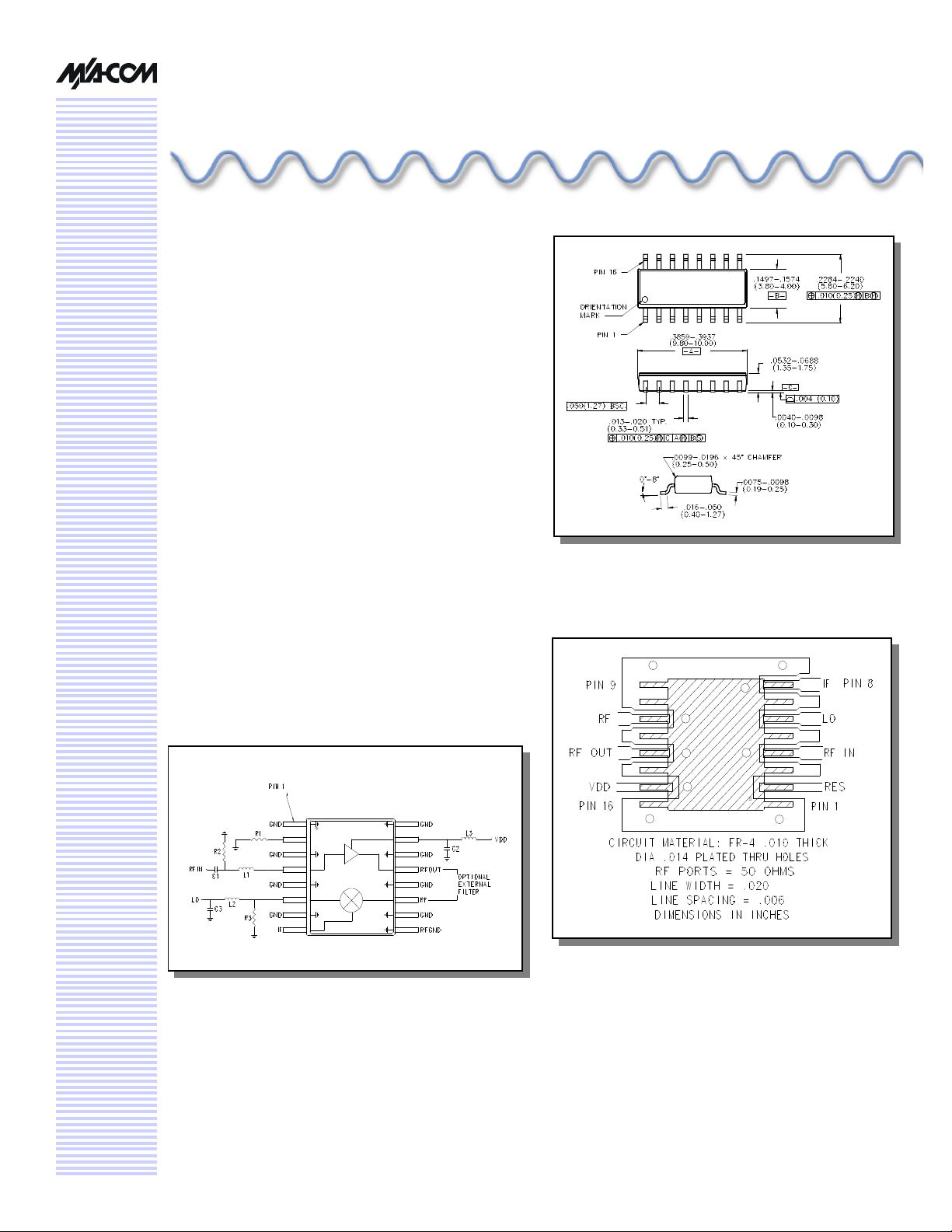
n Surface Mount QSOP16 Package.
n Low Cost/High Performance.
n 50 ohm Nominal Impedance.
Description
M/A-COM’s SA65-0003 is an integrated assembly containing a GaAs FET MMIC LNA and GaAs FET mixer. This
device is packaged in a 16-leaded QSOP plastic surface
mount package. The amplifier can be biased with either
+3V or +5V, the mixer requires no DC bias. The conversion
gain of the integrated combination is typically 6 dB at +3V
bias and 8 dB at +5V bias. The SA65-0003 is ideally
suited for RF/IF communications applications requiring
down conversion with some gain.
This MCM contains a mixer that is fabricated using a
mature 1-micron GaAs process, it also contains an LNA
that is fabricated using a low cost mature 0.5-micron gate
length GaAs MESFET process. Both die feature full
passivation for increased performance and reliability.
QSOP-16
Recommended PCB Layout
Functional Block Diagram
Page 2
Down Converter, 1500 - 2000 MHz
Electrical Specifications TA = +25°C, Z0=50 Ohms, RF = -10 dBm1,
LO = +13 dBm, IDD ≈ 45 mA
Parameter Test Conditions1 Units Min Typical Max
Conversion Gain
Isolation 4 LO to RF IN
Reverse Isolation5 LNA +3V dB 30 40 —
VSWR LO
Input IP3
1. For IP3 measurements, RFIN = -24 dBm, this low RF IN level gets amplified through the LNA.
2. For IP3 measurements, RFIN2 = RFIN1 + 10 MHz, LO = RFIN1—140 MHz.
3. For IP3 measurements, IP3 = IMR/2 + PIN.
4. RF IN to IF Isolation is typically 0 dB.
5. Reverse Isolation is measured from IF to RFIN with the IF at –10 dBm, LO at +13 dBm.
6. The amplifier has a normal gain of 12.5 dB, 3V bias and 14.0 dB, 5V bias. Amplifier typical Noise Figure = 1.5 dB.
7. NFT = NF1 + (NF2 - 1)/G1
6,7
LNA +3V
1,2,3
LNA +3V
LNA +5V
LO to IF
RF IN
IF
LNA +5V
dB
dB
dB
dB
Ratio
Ratio
Ratio
dB
dB
3.1
4.6
29
19
—
—
—
13
21
SA65-0003
6.0
8.0
32
23
1.4:1
1.9:1
1.9:1
17.5
25
V 1.00
6.6
8.8
—
—
—
2.5:1
2.1:1
—
—
Absolute Maximum Ratings
Parameter Absolute Maximum
RF Input Power 9 +17 dBm
LO Drive Power 9 +23 dBm
VDD +10 VDC
Current 10 80 mA
Channel Temperature 11 +150°C
Operating Temperature -40°C to +85°C
Storage Temperature -65°C to +150°C
8. Operation of this device above any one of these
parameters may cause permanent damange.
9. Total power for RF and LO ports should not exceed +23
dBm.
10. When pin #2 is used to increase current—see note 6
above.
11. Thermal resistance (?jc) = +95°C/W.
8
Pin Configuration
Pin # Function Description
1 GND RF and DC Ground
2 RES External current control (optional)
3 GND RF and DC Ground
4 RF IN RF Input of the amplifier
5 GND RF and DC Ground
6 LO LO port of the mixer
7 GND RF and DC Ground
8 IF IF port of the mixer
9 RF GND RF and DC Ground
10 GND RF and DC Ground
11 RF
12 GND RF and DC Ground
13 RF OUT 12 RF output of the amplifier
14 GND RF and DC Ground
15 VDD Positive supply voltage
16 GND RF and DC Ground
12. The output port of the amplifier, RFOUT, and the input
port of the mixer, RF, are adjacently placed so that an
external filter can be used.
12
RF port of the mixer
Specifications subject to change without notice.
n North America: Tel. (800) 366-2266
n Asia/Pacific: Tel.+81-44-844-8296, Fax +81-44-844-8298
n Europe: Tel. +44 (1344) 869 595, Fax+44 (1344) 300 020
Visit www.macom.com for additional data sheets and product information.
2
Page 3

Down Converter, 1500 - 2000 MHz
SA65-0003
V 1.00
External Circuitry Parts 13
Part Value Purpose
C1 47 pF DC Block
C2 47 pF By-pass
C3 3.3 pF LO Port Matching Network
L1 3.9 nH Tuning
L2 3.0 nH LO Port Matching Network
L3 12 nH RF Choke
R1 See Note 14 Optional Current Control
R2 5.1 k Ohms DC Return
R3 330 Ohms LO Port Matching Network
13. All external circuitry parts are readily available, low cost
surface mount components (.060 in. x .030 in. or .080 in.
x .050 in.).
14. Pin 2 allows use of an external resistor to ground for optional higher current. For 20 mA operation, no resistor is
used.
For IDD ≈ 30 mA, R2 = 43 Ohms
For IDD ≈ 45 mA, R2 = 15 Ohms
For IDD ≈ 60 mA, R2 = 10 Ohms
Spurious Table
-12 -37 -65 -75 -75
4X -1.9 -39 -72 -77 -77
Harmonic
of LO (n)
The spurious table shows the spurious signals resulting from
the mixing of the RFIN and LO input signals, assuming down
conversion. The number of dB below the conversion loss
level indicates the mixing products. The lower frequency
mixing term is shown for two different input levels. The top
number is for an RFIN power level of –19 dB; the lower
number is for –29 dB. Assuming the LNA gain is
approximately 14 dB, the mixer input will see approximately
–5 dB and –15 dB.
|mFRF - nFLO|, RF = -19 dB RF = 1850 MHz
|mFRF - nFLO|, RF = -29 dB LO = 1710 MHz
-2.8 -29 -68 -66 -74
3X 7.1 -30 -70 -77 -75
7.0 -27 -37 -68 -74
2X 11.8 -27 -47 -75 -75
4.5 0 -48 -69 -74
1X 11.8 0 -58 -76 -76
N/A -5 -34 -69 -70
0X N/A -5 -46 -75 -70
0X 1X 2X 3X 4X
Harmonic of RFIN (m)
Typical Performance Curves
Gain
+3V +5V
10
8
6
Gain (dB)
4
2
1.5 1.6 1.7 1.8 1.9 2.0
Frequency (GHz)
Specifications subject to change without notice.
n North America: Tel. (800) 366-2266
n Asia/Pacific: Tel.+81-44-844-8296, Fax +81-44-844-8298
n Europe: Tel. +44 (1344) 869 595, Fax+44 (1344) 300 020
Visit www.macom.com for additional data sheets and product information.
Isolation at +3V
40
30
20
Isolation (dB)
10
0
1.5 1.6 1.7 1.8 1.9 2.0
L-I
Frequency (GHz)
L-R
3
Page 4

Down Converter, 1500 - 2000 MHz
Typical Performance Curves
SA65-0003
V 1.00
IIP3
+5V+3V
20
15
10
IIP3 (dB)
5
0
1.5 1.6 1.7 1.8 1.9 2.0
Frequency (GHz)
Ordering Information
Part Number Package
SA65-0003 Bulk Packaging
SA65-0003TR Tape and Reel (1K Reel)
SA65-0003-TB Units Mounted on Test Board
VSWR at +3V
IF LO RF
3.0
2.5
2.0
VSWR
1.5
1.0
1.7 1.8 1.9 2.0
Frequency (GHz)
Specifications subject to change without notice.
n North America: Tel. (800) 366-2266
n Asia/Pacific: Tel.+81-44-844-8296, Fax +81-44-844-8298
n Europe: Tel. +44 (1344) 869 595, Fax+44 (1344) 300 020
Visit www.macom.com for additional data sheets and product information.
4
 Loading...