

Page 1
RF106 900 MHz Power Amplifier
Product Description
The RF106 is a class AB RF power amplifier for 900 MHz
ISM band applications. It delivers output power
proportional to the input signal power.
The RF106 power amplifier, combined with Conexant's
RF105 diSSTance™ (digital Spread Spectrum
Technology) transceiver, forms a complete system
solution for a direct conversion 900 MHz diSSTance radio
which is fully compliant with FCC Part 15 regulations in
the ISM band.
The RF106 is operational in the 900 MHz ISM band with
supply voltage ranging from 2.7V to 5V. It is available in a
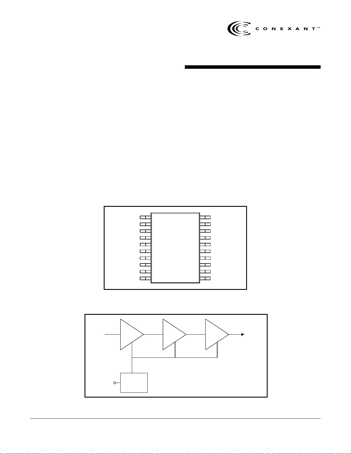
small 20-pin TSSOP package, shown in Figure 1. Figure 2
shows a block diagram for the RF106.
RFOUT
GND1
MATCH
VCC1
NC
VCC2
NC
VCC3
GND2
ENABLE
1
2
3
4
5
6
7
8
9
10
RF106
Features
• Class AB-type RF power amplifier
• 100 mW peak envelope output power
• Very fast settling from standby mode to active
mode
• Efficient high output power operation
• Very few external components required
• 20-pin TSSOP package
Applications
• diSSTance-technology cordless telephone
•
Direct s
• Frequency hopping spread spectrum systems
• Wireless LANs
• Wireless modems
• Wireless security
• Inventory control
20
19
18
17
16
15
14
13
12
11
equence spread spectrum systems
systems
GND9
GND8
GND7
GND6
NC
NC
GND5
GND4
GND3
RFIN
Figure 1. RF106 Pin Signals – 20 Pin TSSOP
RFOUTRFIN
ENABLE
A1 A2 A3
Bias
Figure 2. RF106 Block Diagram
Data Sheet 2/1/99 Order No. W118
Page 2
RF106 900 MHz Power Amplifier
Technical Description
The RF106 is a three stage, class AB RF power amplifier
for the 902-928 MHz ISM band. A class AB power
amplifier allows a wide range of output powers without
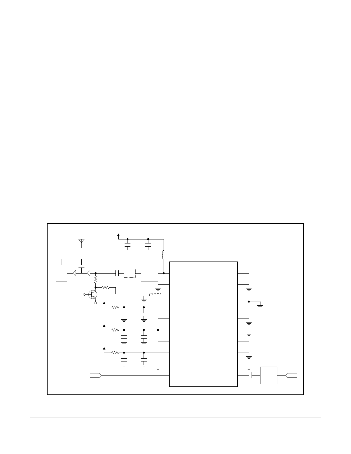
excessive idle power dissipation. Figure 3 shows a typical
application circuit for the RF106.
Recommendations on Layout and Implementation
Matching
An input matching network and an output matching
network are needed for maximum power transfer. For
greatest efficiency, it is recommended that the input
matching network be determined before the output
matching network. Matching network values are layoutsensitive. If the RF106 is used with Conexant's RF105
transceiver, the input matching network is not required if
the connecting traces are short.
A bypassing capacitor of 33pF and a decoupling capacitor
of 1nF for low frequency noise are recommended. Due to
layout variations the value of the capacitor may vary.
General Grounding Requirements
All ground pins should have minimum trace inductance to
ground. If a ground plane cannot be provided right at the
pins, the vias to ground plane should be placed as close
to the pins as possible. There should be one via for each
ground pin, unless otherwise specified. If the ground
plane is at the bottom layer, two vias per pin in parallel
may be required.
It is important to provide pins 13 and 14 with separate
low-impedance connections to GND, isolated from other
top-layer grounds.
NC pins are not used and should be connected to ac
ground, Vcc or ground, as shown in Figure 3.
Bypassing
All VCC pins should have proper bypassing. These
decoupling capacitors should be placed very close to the
pins, preferably right at the Vcc pins.
Vcc
33pF
Output
matching
network*
1.5nH
Rx
section
90°
phase
shifter
Matching
network*
33pF
470
ENABLE
10k
Vcc
Vcc
Vcc
1nF
LPF
33pF
Ω
Ω
10
1nF
10
1nF
10
1nF
33pF
Ω
33pF
Ω
33pF
22nH
ESD Sensitivity
The RF106 is a static-sensitive electronic device. Do not
operate or store near strong electrostatic fields. Take
proper Electrostatic Discharge (ESD) precautions.
1
2
3
4
5
RF106
6
7
8
9
10
20
19
18
17
16
15
14
13
12
11
33pF
* Matching network values are layout-dependent.
Input
matching
network*
RFIN
Figure 3. RF106 Typical Application Circuit
2
Conexant
W118
2/1/98
Page 3

RF106 900 MHz Power Amplifier
Interface Description
Table 1 describes the pin signals for the RF106.
Table 1. Pin Signal Description
Pin No. Name Description
1 RFOUT Power amplifier output
Connect to power supply through an inductor; matching network required before connecting to antenna.
2 GND1 Ground
3 MATCH Interstage matching
Connect to ground through a 1.5 nH (typical) inductor.
4 VCC1 Power supply
5 NC Not used
Connect to ac ground, Vcc or ground (Figure 3).
6 VCC2 Power supply
Internally connected to middle stage matching network.
7 NC Not used
Connect to ac ground, Vcc or ground (Figure 3).
8 VCC3 Power supply
9 GND2 Ground
10 ENABLE Chip enable (active high)
11 RFIN Power amplifier input
12 GND3 Ground
13 GND4 Ground
14 GND5 Ground
15 NC Not used
Connect to ac ground, Vcc or ground (Figure 3).
16 NC Not used
Connect to ac ground, Vcc or ground (Figure 3).
17 GND6 Ground
18 GND7 Ground
19 GND8 Ground
20 GND9 Ground
W118
2/1/99
Conexant
3
Page 4

RF106 900 MHz Power Amplifier
Specifications
Table 2 lists the absolute maximum ratings for the RF106.
Table 3 gives the electrical specifications for the RF106.
Table 2. Absolute Maximum Ratings
Parameter Min. Max. Unit
Supply voltage (Vcc)
Input voltage range
Power dissipation @ high output power mode 400 mW
Ambient operating temperature –10 +70 °C
Storage temperature –40 +125 °C
Notes:
1. Voltages are referenced to GND.
(note 1)
(note 1)
+5 V
GND VCC V
Table 3. RF106 Electrical Specifications
(note 1)
Parameter Min. Typ. Max. Units
Gain variation vs. frequency (902–928 MHz)
Peak-Envelope output Power (PEP)
RF gain 26 29 30 dB
Total supply current: Output PEP = 21 dBm
IM3: PEP ≤ 21 dBm –21 –17 dBc
Output VSWR for unconditional stability 10:1
RF input return loss (902–928 MHz) –9.5 dB
RF output-to-input isolation @ 915 MHz 50 dB
RF input impedance 50
RFOUT passband 3dB BW around 915 MHz 250 MHz
VIH for ENABLE 1.9 V
VIL for ENABLE 0.8 V
IIH for ENABLE 50 60
IIL for ENABLE –10 –1 0
Power supply for specified performance 3.0 3.6 5.0 V
Power supply range 2.7 3.6 5.0 V
Operating temperature range –10 25 70
Notes:
1. Test conditions: T
2. With continuous wave RF input signal of –8 dBm.
3. With continuous wave RF input signal of –18 dBm.
4. With continuous wave RF input signal of –28 dBm.
5. When ENABLE (pin 10) is low.
= 25 °C, VCC = 3.3V, f
A
(note 2)
Output PEP = 11 dBm
Output PEP = 1 dBm
Standby
(note 5)
REF
= 915 MHz
18 21 22 dBm
±
0.15
95
40
30
< 1
(note 2)
(note 3)
(note 4)
±
0.75 dB
mA
mA
mA
µ
Ω
µ
µ
°
A
A
A
C
4
Conexant
W118
2/1/98
Page 5

RF106 900 MHz Power Amplifier
Device Dimensions
Package dimensions for the RF106 are given in Figure 4.
D
E1
E
PIN 1 REF
e b
TOP VIEW
A2
A
A1
DETAIL A
See detail A
E1
SIDE VIEW
Millimeters
Dim.
A 1.20 MAX 0.0473 MAX
A1 0.05 0.10 0.0020 0.0039
A2 0.90 NOM 0.0354 NOM
D 6.45 6.55 0.2540 0.2580
E 6.30 6.50 0.2481 0.2560
E1 4.30 4.50 0.1694 0.1772
L 0.50 0.75 0.0197 0.0295
L1 1.00 REF 0.0394 REF
e 0.65 BSC 0.0256 BSC
b 0.17 0.27 0.0067 0.0106
c 0.13 0.20 0.0051 0.0079
Coplanarity 0.08 MAX 0.003 MAX
Ref: 20-PIN TSSOP (GP00-D296)
c
L
L1
*Metric values (millimeters) should be used for PCB
layout. English values (inches) are converted from
metric values and may contain round-off errors.
Min. Max. Min. Max.
Inches*
Figure 4. Package Dimensions – 20-pin TSSOP
Information provided by Conexant Systems, Inc. is believed to be accurate and reliable. However, no responsibility is
assumed by Conexant for its use, nor any infringement of patents or other rights of third parties which may result from its use.
No license is granted by implication or otherwise under any patent rights of Conexant other than for circuitry embodied in
Conexant products. Conexant reserves the right to change circuitry at any time without notice. This document is subject to
change without notice.
Conexant, “What’s Next in Communications Technologies” and diSSTance are trademarks of Conexant Systems, Inc.
Product names or services listed in this publication are for identification purposes only, and may be trademarks or registered
trademarks of their respective companies. All other marks mentioned herein are the property of their respective holders.
©1999, Conexant Systems, Inc.
Printed in U.S.A.
All Rights Reserved
W118
Conexant
5
2/1/99
Page 6

Further Information:
literature@conexant.com
1-800-854-8099 (North America)
33-14-906-3980 (International)
Web Site
www.conexant.com
China
Phone: (86 2) 6361 2515
Fax: (86 2) 6361 2516
Hong Kong
Phone: (852) 2 827 0181
Fax: (852) 2 827 6488
World Headquarters
Conexant Systems, Inc.
4311 Jamboree Road,
P.O. Box C
Newport Beach, CA 92658-8902
Phone: (949) 483-4600
Fax: (949) 483-6375
U.S. Florida/South America
Phone: (813) 799-8406
Fax: (813) 799-8306
U.S. Los Angeles
Phone: (805) 376-0559
Fax: (805) 376-8180
U.S. Mid-Atlantic
Phone: (215) 244-6784
Fax: (215) 244-9292
U.S. North Central
Phone: (630) 773-3454
Fax: (630) 773-3907
U.S. Northeast
Phone: (978) 692-7660
Fax: (978) 692-8185
U.S. Northwest/Pacific West
Phone: (408) 249-9696
Fax: (408) 249-7113
U.S. South Central
Phone: (972) 733-0723
Fax: (972) 407-0639
U.S. Southeast
Phone: (770) 246-8283
Fax: (770) 246-0018
U.S. Southwest
Phone: (949) 222-9119
Fax: (949) 222-0620
APAC Headquarters
Conexant Systems Singapore,
Pte. Ltd.
1 Kim Seng Promenade
Great World City
#09-01 East Tower
Singapore 237994
Phone: (65) 737 7355
Fax: (65) 737 9077
Australia
Phone: (61 2) 9869 4088
Fax: (61 2) 9869 4077
India
Phone: (91 11) 692 4780
Fax: (91 11) 692 4712
Korea
Phone: (82 2) 565 2880
Fax: (82 2) 565 1440
Europe Headquarters
Conexant Systems France
Les Taissounieres B1
1680 Route des Dolines
BP 283
06905 Sophia Antipolis Cedex
France
Phone: (33 4) 93 00 33 35
Fax: (33 4) 93 00 33 03
Europe Central
Phone: (49 89) 829 1320
Fax: (49 89) 834 2734
Europe Mediterranean
Phone: (39 02) 9317 9911
Fax (39 02) 9317 9913
Europe North
Phone: (44 1344) 486 444
Fax: (44 1344) 486 555
Europe South
Phone: (33 1) 41 44 36 50
Fax: (33 1) 41 44 36 90
Middle East Headquarters
Conexant Systems Commercial
(Israel) Ltd.
P.O. Box 12660
Herzlia 46733
Israel
Phone: (972 9) 952 4064
Fax: (972 9) 951 3924
Japan Headquarters
Conexant Systems Japan Co., Ltd.
Shimomoto Building
1-46-3 Hatsudai,
Shibuya-ku
Tokyo, 151-0061
Japan
Phone: (81 3) 5371 1567
Fax: (81 3) 5371 1501
Taiwan Headquarters
Conexant Systems, Taiwan Co., Ltd.
Room 2808
International Trade Building
Keelung Road, Section 1
Taipei 110
Taiwan, ROC
Phone: (886 2) 2720 0282
Fax: (886 2) 2757 6760
 Loading...