

Page 1
Liquid crystal displays
20 characters2 lines COG module
RCM2072R
The RCM2072R is a reflective TN type liquid crystal module with a built-in controller/driver LSI and a display capacity
of 20 characters2 lines.
Applications
Printers, copiers, facsimiles, etc.
Features
1) Wide viewing angle and high contrast.
2) 57 dot character matrix with cursor.
3) Interfaces with 4-bit or 8-bit MPUs.
4) Displays up to 237 characters and special symbols
5) Custom character patterns are displayed with the
character RAM.
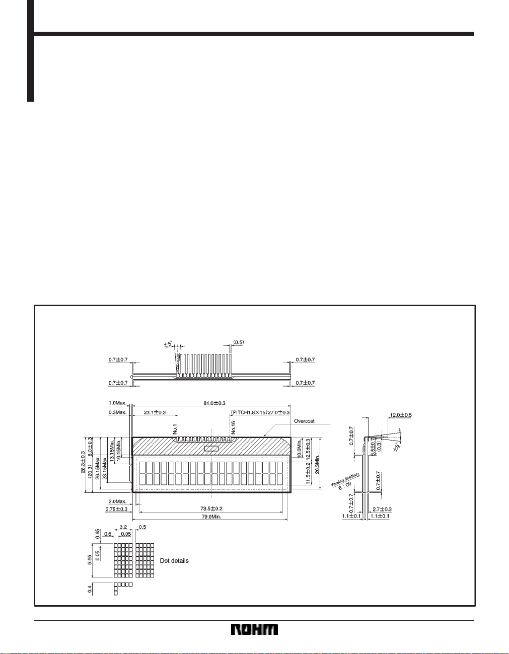
External dimensions (Units: mm)
6) Abundant instruction set including clear display , cursor on/off, and character blinking.
7) Compact and lightweight for easy assembly to the
host instrument.
8) Operable on single 5V power supply.
9) Low power consumption.
29
Page 2
Liquid crystal displays RCM2072R
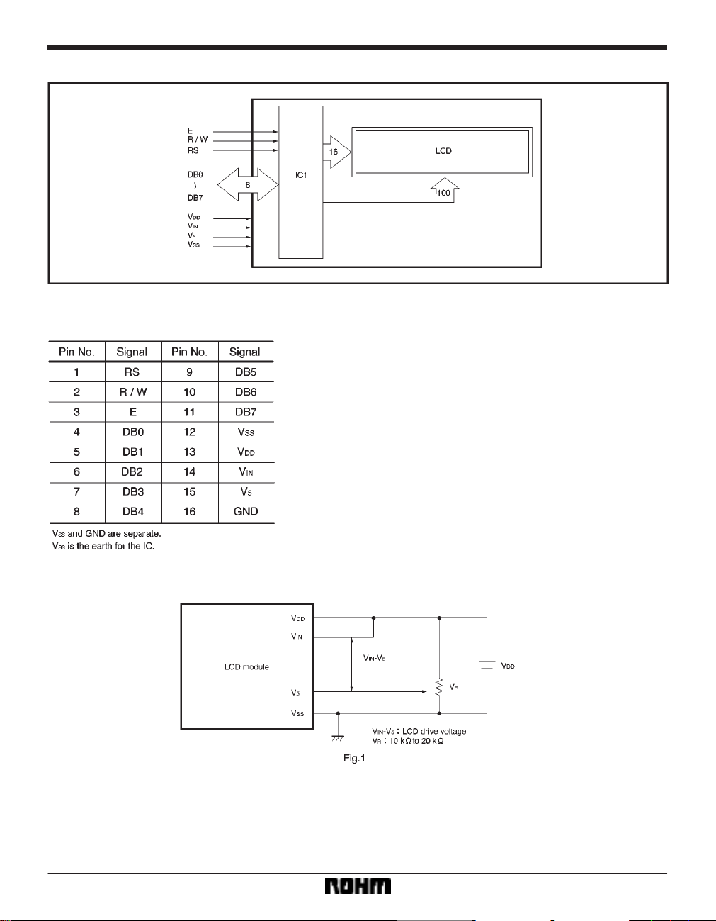
Block diagram
Pin assignments
Power supply example
30
Page 3
Liquid crystal displays RCM2072R
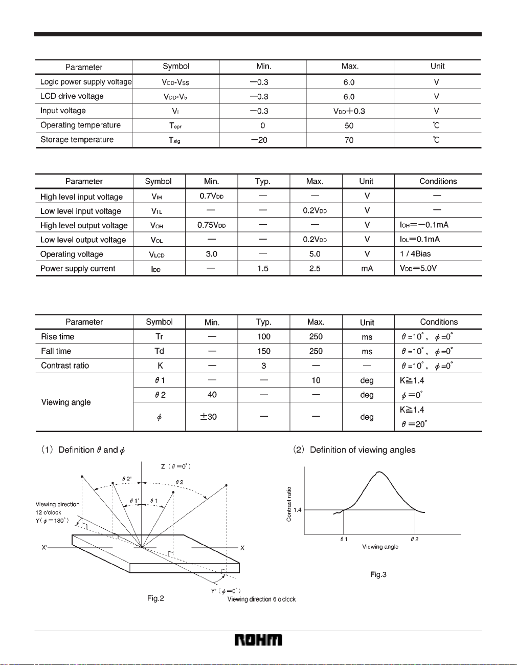
FAbsolute maximum ratings (Ta = 25_C)
FElectrical characteristics (V
FOptical characteristics (Ta = 25_C)
When viewing from below
DD = 5.0 ± 5%, Ta = 25_C)
31
Page 4

Liquid crystal displays RCM2072R
Pin functions
Note: In order to be able to interface with 4-bit or 8-bit MPUs, the module supports data transfer with two
transmissions of 4 bits at a time or one transmission of 8 bits at once.
(1) When the interface data length is 4 bits, data is transferred between the MPU along DB4 through DB7
buses and DB0 through DB3 buses are not used. Data transferral is completed after two transfers of 4 bit
data. First the upper nibble (contents of DB4 through DB7 during 8-bit interfacing) is transferred and then
the lower nibble (contents of DB0 through DB3 during 8-bit interfacing) is transferred. Check for busy
flag occurs after the second 4-bit data (one instruction) is transferred. At that time, the busy flag and
address counter data is also output in two 4-bit increments.
(2) When the interface data length is 8 bits, the data DB0 through DB7 is transferred along the eight data
buses.
32
Page 5

Liquid crystal displays RCM2072R
Timing chart
(1) Writing
33
Page 6

Liquid crystal displays RCM2072R
(2) Reading
34
Page 7

Liquid crystal displays RCM2072R
Instructions
(Example) When fosc = 270kHz
40µs
250
270
= 37µs
35
Page 8

Liquid crystal displays RCM2072R
Character code and corresponding character pattern
36
Page 9

Liquid crystal displays RCM2072R
FReset function
When you turn on the power supply, the module automatically returns to its initial (reset) settings. At the initial settings,
the busy flag (BF) becomes “1.” The busy status last 10 ms from when V
instructions are carried out.
(1) Clear display
(2) Function set
8-bit interface data length (DL = 1)
Two line display (N = 1)
SEG signal transfer direction SEG1SEG50SEG51SEG100 (SD1 = 0, SD2 = 0)
COM signal transfer direction COM1COM16 (CD = 0)
(3) Display on/off control
Display off (D = 0)
Cursor off (C = 0)
Blinking off (B = 0)
(4) Entry mode set
+1 (increment) (I/D = 1)
No shift (S = 0)
∗The internal reset circuit may not operate properly due to conditions with the power supply. If this is the case, use the
appropriate instruction to reset the settings.
FOperation notes
(1) Handling precautions
S Protect the module from strong shocks as they can
cause damage or defective operation.
S The polarizing plate on the surface of the module is
soft and can easily be scratched. Wipe away dirt and
dust using an alcohol-based cleanser.
S If the liquid crystal panel is damaged and liquid crystal
contacts your clothing or body, wash immediately with
soap and water.
S If the module is to be used for long periods subjected
to direct sunlight, employ a filter to block the ultraviolet
rays.
S Do not use the module in areas of high temperature
or high humidity. Do not use the module in locations
exposed to direct sunlight or fluorescent light.
S A protective film (polyethylene) is pasted over ROHM
liquid crystal modules to protect the panel surfaces.
When peeling this film off, be sure to peel as slow as
possible in order to minimize the generation of static
electricity.
(2) Precautions during operation
DD reaches 4.5V . At the initial settings, following
S Do not connect or disconnect the module while the
power supply is turned on.
S Input the input signal after the module power supply
is turned on. When turning it off, turn off the input signal first. Otherwise the IC may be damaged by the
latch-up phenomenon.
37
 Loading...