

Page 1

NTE2060 & NTE2061
Integrated Circuit
PMOS LSI Alarm Clock Circuit
Applications:
D Alarm Clock
D Clock Radio
D Timer for Home Appliances
D Display of Elapsed Time
Functions:
D Real Time Display
D Alarm With Snooze Function
D Sleep Timer (59 Minutes Max)
Features:
D Single Chip P–Channel ED MOS LSI
D Direct Drive Capable:
LED (5mA or More, Red LED)
Fluorescent Display Tube (Light–Up Voltage 16V or Less)
D Wide Operating Voltage Range: –8V to –16V
D Capable of 50Hz or 60Hz Reference Frequency
D Two Selections of Display Mode:
AM/PM 12–Hour
24–Hour
D 24–Hour Alarm Function
D Repeatable Snooze Function
D Presettable 59–Minute Down Counter (Sleep Timer)
D SNOOZE Pin can be used to Set the Sleep Timer with One Touch
D Clock Input Noise Eliminator
D Power Failure Indicating Function (All Digits Flashing):
12H Display Mode → AM or OUTPUT of LSI
24H Display Mode → AM, PM or b & c OUTPUT of LSI
Page 2
Absolute Maximum Ratings: (TA = +25°C, VSS = 0V unless otherwise specified)
Maximum Supply Voltage, VDDmax –18 to +0.3V. . . . . . . . . . . . . . . . . . . . . . . . . . . . . . . . . . . . . . . . . . .
Input Voltage, V
IN
Output Voltage (Output Pin OFF), V
OUT
VDD –0.3 to +0.3V. . . . . . . . . . . . . . . . . . . . . . . . . . . . . . . . . . . . . . . . . . . . . . . . . . . . .
VDD –0.3 to +0.3V. . . . . . . . . . . . . . . . . . . . . . . . . . . . . . . . . .
Allowable Power Dissipation (TA = +70°C), PDmax 900mW. . . . . . . . . . . . . . . . . . . . . . . . . . . . . . . . . .
Operating Temperature Range, T
Storage Temperature Range, T
stg
opr
–30° to +70°C. . . . . . . . . . . . . . . . . . . . . . . . . . . . . . . . . . . . . . . . .
–55° to +125°C. . . . . . . . . . . . . . . . . . . . . . . . . . . . . . . . . . . . . . . . . .
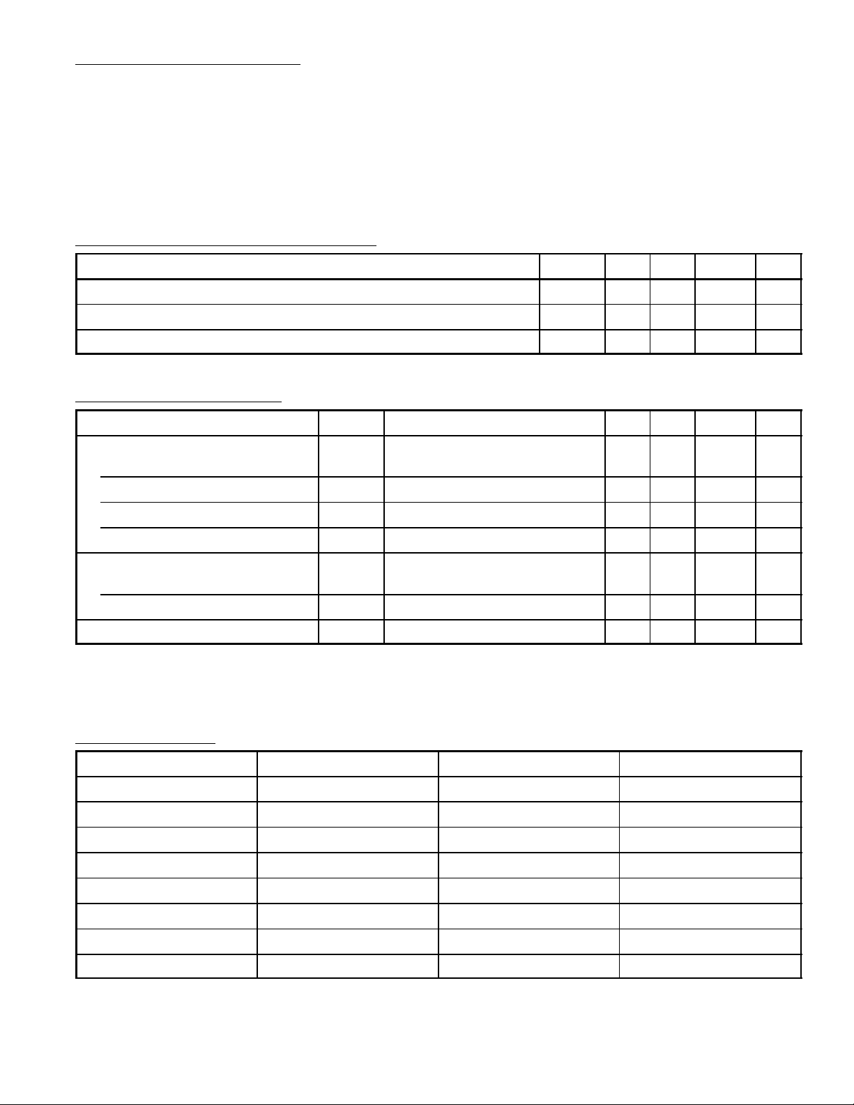
Recommended Operating Conditions: (TA = +25°C, VSS = 0V unless otherwise specified)
Parameter Symbol Min Typ Max Unit
Supply Voltage V
Input “H” Level Voltage V
Input “L” Level Voltage V
DD
IH
IL
–16 –12 –8 V
–1 – 0 V
V
DD
– VDD +2 V
Electrical Characteristics: (TA = +25°C, VSS = 0V, VDD = 12V ±2V unless otherwise specified)
Parameter Symbol Test Conditions Min Typ Max Unit
Output “H” Level Current
ALARM OUT, SLEEP OUT
b & c, a & d I
1Hz I
All Other Outputs I
I
OH (1)
OH (2)
OH (3)
OH (4)
VOH = VSS – 2V 0.5 – – mA
VOH = VSS – 2.5V 10 – – mA
VOH = VSS – 2.5V 13 – – mA
VOH = VSS – 2.5V 5 – Note 1 mA
Output Leakage Current
ALARM OUT, SLEEP OUT
All Other Outputs I
Current Dissipation I
I
OL (1)
OL (2)
DD
VOL = V
DD
– – 5 µA
VOL = VDD + 1.8V – – 50 µA
VDD = –12V – 3 – mA
Note 1. 11mA Max is allowed in the range where the power dissipation is 900mW and 1.2W at
TA = +70°C and +25°C respectively.
Function Table A:
Alarm Display Input Seconds Display Input Sleep Display Input Display Mode
L L L Real Time Display
H L L Alarm Display
L H L Seconds Display
H H L Alarm Display
L L H Sleep Display
H L H Sleep Display
L H H Sleep Display
H H H Sleep Display
Note 2. “H”: Input Pin ––– VSS Level
“L”: Input Pin ––– VDD Level (or Open)
Page 3

Function Table B:
Display
Mode
Time Setting
Input Pin
FAST Minutes contents advance at a 60Hz (Note 3) rate.
Real Time
Display
SLOW Minutes contents advance at a 2Hz rate.
BOTH Minutes contents advance at a 60Hz (Note 3) rate.
FAST Minutes contents advance at a 60Hz (Note 3) rate.
Alarm
Display
SLOW Minutes contents advance at a 2Hz rate.
BOTH AM 12:00 is set when in the 12–hour display mode.
0:00 is set when in the 24–hour display mode.
FAST 00 seconds is set. No carry to minutes is generated.
Seconds
Display
SLOW Seconds counting is stopped (Held).
BOTH (When in the 12–hour display mode) the real time counter is set to AM 12:00.
(When in the 24–hour display mode) the real time counter is set to 0:00.
FAST Minutes contents advance at a 60Hz (Note 3) rate.
Sleep
Display
Display
SLOW Minutes contents advance at a 2Hz rate.
BOTH Minutes contents advance at a 60Hz (Note 3) rate.
Note 3. For 50Hz use, 50Hz shall apply.
Function
Note 4. Both means that 2 input pins of FAST and SLOW are set to “H”.
Pin Connection Diagram
AM Output
10 Hrs b & c
10 Mins f 10 31 Alarm Display Input
10 Mins g Sleep Display Input
10 Mins–a & d
10 Mins b
10Mins e
10 Mins c
1
2
Hrs f
3
Hrs g
4
Hrs a
5
Hrs b
6
Hrs d
7
8 33
Hrs c
Hrs e Second Display Input
9 32
11 30
12 29
13
14
15
Mins f
16 25
Mins g Snooze Input
17 24
Mins a 18 23 Output Common Source
Mins b Mins–c
19 22
Mins e
20 21
40
PM Output
Colon (1H
39
12/24 Hr Select
38
37 N.C./Blanking Input*
36
50/60 H
35
50/60 HZ Input
34 Fast Set Input
Slow Set Input
V
DD
28
V
SS
27 Sleep Output
26 Alarm Off Input
Alarm Output
Mins–d
Z
Select
Z
)
Note: N.C. pin must not be used for external connection such as a relay point.
Pin 37 is Blanking Input on the NTE2061
Page 4

40 21
1
2.055 (52.2)
.100 (2.54) .019 (0.5)
20
.155 (3.9)
.137
(3.5)
.550 (13.9)
Max
.650 (16.5)
 Loading...