

Page 1
Integrated Circuit
PMOS Digital Alarm Clock
Features:
D Single–Chip ED MOS LSI
D LED Direct Drive by Time–Sharing (Duplex)
D Wide Operating Voltage Range
D Alarm on a 24–Hour Basis
D Two Selections of Time Format:
AM/PM 12–Hour Basis & 24–Hour Basis
D On–Chip CR Oscillator for Battery Backup
D 50Hz or 60Hz Reference Frequency
NTE2062
D Automatic Advance Capable:
“Hours”, “Minutes”
D Sleep Timer:
Max. 59 Minutes or 1Hour, 59 Minutes
D Repeatedly Usable Snooze
D Power Failure Indicator
D 900Hz Output for Alarm Tone
Functions:
D Real Time Display
D Alarm with Snooze
Applications:
D Alarm Clock
D Clock Radio
D Sleep Timer
Absolute Maximum Ratings: (VSS = 0, TA = +25°C unless otherwise specified)
Maximum Supply Voltage, VDDmax –15 to +0.3V. . . . . . . . . . . . . . . . . . . . . . . . . . . . . . . . . . . . . . . . . . .
Input Voltage, V
IN
50/60Hz –15 to +0.3V. . . . . . . . . . . . . . . . . . . . . . . . . . . . . . . . . . . . . . . . . . . . . . . . . . . . . . . . . . . . .
Other Than 50/60Hz –15 to +0.3V. . . . . . . . . . . . . . . . . . . . . . . . . . . . . . . . . . . . . . . . . . . . . . . . . .
Output Voltage, V
OUT
Input Clamp Current, I
IN
–15 to +0.3V. . . . . . . . . . . . . . . . . . . . . . . . . . . . . . . . . . . . . . . . . . . . . . . . . . . . . . .
–0.4 to +0.4mA. . . . . . . . . . . . . . . . . . . . . . . . . . . . . . . . . . . . . . . . . . . . . . . . . . .
Allowable Power Dissipation (TA = +70°C), PDmax 700mW. . . . . . . . . . . . . . . . . . . . . . . . . . . . . . . . . .
Operating Temperature Range, T
Storage Temperature Range, T
stg
opr
–30° to +70°C. . . . . . . . . . . . . . . . . . . . . . . . . . . . . . . . . . . . . . . . .
–55° to +125°C. . . . . . . . . . . . . . . . . . . . . . . . . . . . . . . . . . . . . . . . . .
Allowable Operating Ranges: (VSS = 0, TA = +25°C unless otherwise specified)
Parameter Symbol Test Conditions Min Typ Max Unit
Supply Voltage V
Input “HIGH” Level Voltage V
DD
IH
50/60Hz Input –1.0 – – V
Other Than 50/60Hz Input –1.5 – – V
–14 – –7.5 V
Input “LOW” Level Voltage V
Input Voltage on 50/60Hz V
AC–IN
50/60Hz – – VDD+2 V
IL
Other Than 50/60Hz – – VDD+2 V
Referenced to V
SS
V
LED
– – V
Page 2
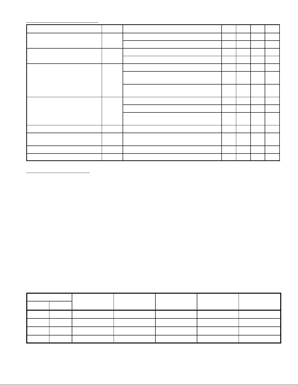
Electrical Characteristics: (VDD = –12V, TA = +25°C unless otherwise specified)
Parameter Symbol Test Conditions Min Typ Max Unit
Input “HIGH” Level Current I
Input “LOW” Level Current I
Output “HIGH” Level Current I
Output Leakage Current I
Power Failure Detect Voltage V
Current Dissipation I
Stability of Oscillator for Backup F
Accuracy of Oscillator for Backup F
OH
OF
CC
VIN = VSS, 50/60Hz – – 10 µA
IH
VIN = VDD, Input Pins other than 50/60Hz – – 20 µA
VIN = V
IL
50/60Hz – – 10 µA
DD,
VIN = VDD, Input Pins other than 50/60Hz – – 10 µA
Alarm Out, Sleep Out, VOH = VSS–1V 5 – – mA
10’s Hr ag & de (24Hr Mode), V
OUT
=
36 – – mA
VSS–1V
Segment Outputs other than above,
V
= VSS–1V
OUT
Alarm Out, Sleep Out, V
10’s Hr ag & de (24Hr Mode), V
Segment Outputs other than above,
V
= V
OUT
DD
DD
Output: OFF, Input with Pull–Down
OUT
= V
DD
OUT
= V
DD
18 – – mA
– – 10 µA
– – 20 µA
– – 20 µA
–7.5 –5.0 – V
– 5 7 mA
Resistor: Open
Typical value, 900Hz, VDD = –9V ±10% –10 – +10 %
S
Typical value, 900Hz, VDD = –9V ±10% –10 – +10 %
A
Operation Description:
50Hz/60Hz Input:
The On–Chip Schmitt Trigger circuit allows a simple RC filter at the input to remove possible line voltage transients. An internal pull–up resistor is provided.
CR Input: (Note 1)
When AC power–down occurs, the time counter enters the “hold” mode and the on–chip clock oscillator starts operating immediately. I f there is no input at “50/60Hz input” during 3–clock period, this oscillator controls the time counter advance instead of “50/60Hz input”. The values of CR determine the
frequency of the on–chip clock oscillator. All segment outputs are of f during backup operation. If the
backup OSC is used at the power–down mode, “50/60Hz input” must be open or at VSS level.
50/60Hz Select Input:
Connecting “50/60Hz select” to VSS enables 50Hz operation. For 60Hz operating, “50/60Hz select”
is left unconnected: Pull–down to VDD is provided by the internal pull–down resistor.
Display Mode Select Input (Alarm Display/Sleep Display):
The internal pull–down resistor allows the use of 2 SPST (single–pole single–throw) switches to select
4 display modes listed in Table 1.
Table 1. Display Mode
Select Input
Alarm Sleep
Display Mode Digit No.1 Digit No. 2 Digit No. 3 Digit No. 4
N.C. N.C. Time Display 10’s Hour, AM/PM Hour 10’s Minute Minute
V
SS
N.C. V
V
SS
N.C. Alarm Display 10’s Hour, AM/PM Hour 10’s Minute Minute
SS
V
SS
Sleep Display Blanked Hour 10’s Minute Minute
Seconds Display Blanked Minute 10’s Second Second
Note 1. If VSS is applied to 2 input of “alarm display” and “sleep display” simultaneously, the seconds
display mode is entered.
Page 3

Operation Description (Cont’d):
Time Setting Input:
Two setting inputs for ’Hours’ and ’Minutes’ are provided. The application of VSS causes the time setting in Table 2 to occur. An internal pull–down resistor each is provided.
Table 2. Setting Contents
Display Mode Set Input Functions
Time Hour ’Hours’ are incremented +1 immediately and advance at a 2Hz rate 1/4 to 3/4
seconds later.
Minute ’Minutes’ are incremented +1 immediately and advance at a 2Hz rate 1/4 to 3/4
seconds later.
Both Both operations shown above are preformed.
Seconds Hour (Note 2) ’Seconds’ are cleared to [00].
(Alarm & Sleep)
Alarm Hour ’Hours’ are incremented +1 immediately and advance at a 2Hz rate 1/4 to 3/4
Minute “Hold” mode.
Both (Note 3) ’Hours” and ’Minutes’ are reset to [0:00] (24–Hour basis) or [12:00] (12–Hour basis)
seconds later.
Minute ’Minutes’ are incremented +1 immediately and advance at a 2Hz rate 1/4 to 3/4
seconds later.
Both ’Hours” and ’Minutes’ are reset to [0:00] (24–Hour basis) or [12:00] (12–Hour basis)
Sleep – The moment VDD is applied to “Sleep Display”, the sleep counter is set to [:59].
Hour The moment VDD is applied to “Sleep Display” and “Hour Set” simultaneously,
the sleep counter is set to [1:59].
Minute The sleep counter counts down at a 2Hz rate.
Both The sleep counter counts down at a 2Hz rate.
Note 2. When “Seconds” display is at 50 to 59, “Seconds” are reset to [00] and a carry occurs to incre-
ment “Minutes” +1.
Note 3. Once the reset mode or hold mode is entered, another function is locked until both “Hour Set”
input and “Minute Set” inputs are released.
12/24–Hour Select Input:
Leaving this pin unconnected (VDD) causes the 12–Hour basis to be selected; connecting this pin
to VSS causes the 24–Hour basis to be selected. An internal pull–down resistor is provided.
Power Failure Indicator:
If the power supply voltage drops and is applied again, all the on–segments flash and the power failure
indication mode is entered. The power failure indication mode is released by applying VSS to “Hour
Set” or “Minute Set”.
Alarm Operation and Alarm Output:
When the alarm set time is reached, the alarm signal is delivered. This signal continues to be delivered for 1 hour 59 minutes unless reset by “Alarm Off” or “Snooze Input”. This signal is provided for
the tone–signal of 900Hz with 50% duty of 2Hz gated. A simple LPF can be used to turn this alarm
signal into DC signal as required.
Snooze Input:
By momentarily connecting this pin to VSS at the alarm on–state, the alarm output is inhibited for 8
to 9 minutes, after which the alarm signal is delivered again. The snooze function can be used repeatedly for 1 hour 59 minutes. An internal pull–down resistor is provided. By connecting “Snooze Input”
to VSS at the alarm off–state, the sleep timer counter is reset to [0:00]. (The sleep timer is reset with
one touch).
Page 4
Operation Description (Cont’d):
Alarm Off Input:
Connecting this i n p u t p i n t o V
inhibits the alarm output momentarily. An internal pull–down resistor
SS
is provided.
Sleep Timer and Sleep Output:
The sleep output can be used to keep the radio turned on for any period of time up to 59 minutes or
1 hour 59 minutes. Table 2 shows how to select the period (59 minutes or 1 hour 59 minutes). This
sleep timer uses a down counter . When the counter contents reach [00], the output stops being delivered, turning off the radio. By connecting “Snooze Input” to V
at the sleep output on–state, the sleep
SS
output is inhibited.
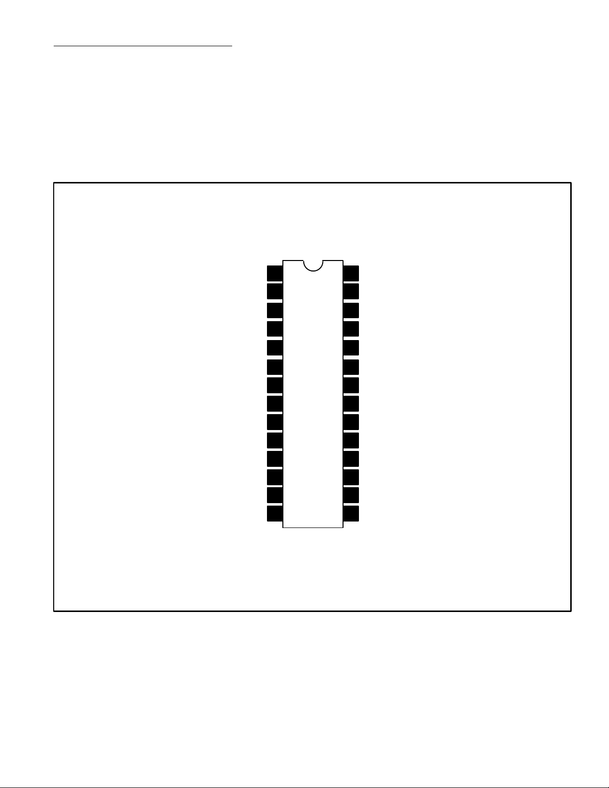
Pin Connection Diagram
AM & 10’s Hr ag & de
PM & 10’s Hr b
10’s Hr c & Hr c
Hr b & g
10’s Min b & g
Min b & g
Min c & d
Min a & f
1
2
3
4
5Hr c & d
6Hr a & f
710’s Min a & f
8
28
27
26
25
24
23
22
21
910’s Min c & d 20
1010’s Min e & Min e
11
19
18
16
14Colon Out 15
12/24 Hr Select
CR Input
50/60Hz Select
50/60Hz Input
Snooze Input
Sleep Input
Hour Set
Min Set
V
DD
Alarm Disp
Alarm Off
Sleep Out12 17
Alarm Out13
V
SS
Page 5

28 15
114
1.070 (27.17)
.070 (1.78)
.910 (23.11)
Max
.194
(4.95)
.122
(3.1)
Min
.338
(8.6)
.400
(10.16)
 Loading...