

Datasheet NTE16001-ECG, NTE16003-ECG, NTE16005-ECG, NTE16006-ECG, NTE16010-ECG Datasheet (NTE)
...Page 1
NTE16000–ECG thru NTE16022–ECG
Polymeric Positive Temperature Coefficient (PTC)
Resettable Fuses
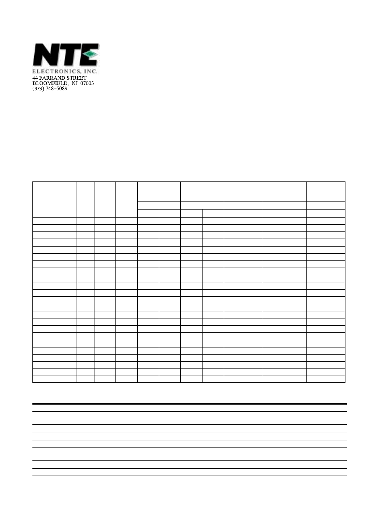
ELECTRICAL CHARACTERISTICS
I
Hold
I
Trip
Initial resistance
1 Hour (R1)
Post–Trip
Resistance
Max. Time
To Trip at 5*lh
Tripped Power
Dissipation
Amperes at 235C Ohms at 235C Ohms at 235C Seconds at 235C Watts at 235C
NTE Type No.
Diag.
No.
V max.
Volts
I max.
Amps
Hold Trip Min. Max Max.
16000–ECG 629 60 40 0.10 0.20 2.50 4.50 7.50 4.0 0.38
16001–ECG 629 60 40 0.17 0.34 2.00 3.20 8.00 3.0 0.48
16002–ECG 629 60 40 0.20 0.40 1.50 2.84 4.40 2.2 0.40
16003–ECG 629 60 40 0.25 0.50 1.00 1.95 3.00 2.5 0.45
16004–ECG 629 60 40 0.30 0.60 0.76 1.36 2.10 3.0 0.50
16005–ECG 629 60 40 0.40 0.80 0.52 0.86 1.29 3.8 0.55
16006–ECG 629 60 40 0.50 1.00 0.41 0.77 1.17 4.0 0.75
16007–ECG 629 60 40 0.65 1.30 0.27 0.48 0.72 5.3 0.90
16008–ECG 629 60 40 0.75 1.50 0.18 0.40 0.60 6.3 0.90
16009–ECG 629 60 40 0.90 1.80 0.14 0.31 0.47 7.2 1.00
16010–ECG 630 30 40 0.90 1.80 0.07 0.12 0.22 5.9 0.60
16011–ECG 629 30 40 1.10 2.20 0.10 0.18 0.27 6.6 0.70
16012–ECG 629 30 40 1.35 2.70 0.065 0.115 0.17 7.3 0.80
16013–ECG 629 30 40 1.60 3.20 0.055 0.105 0.15 8.0 0.90
16014–ECG 629 30 40 1.85 3.70 0.04 0.07 0.11 8.7 1.00
16015–ECG 630 30 40 2.50 5.00 0.025 0.048 0.07 10.3 1.20
16016–ECG 630 30 40 3.00 6.00 0.02 0.05 0.08 10.8 2.00
16017–ECG 630 30 40 4.00 8.00 0.01 0.03 0.05 12.7 2.50
16018–ECG 630 30 40 5.00 10.00 0.01 0.03 0.05 14.5 3.00
16019–ECG 630 30 40 6.00 12.00 0.005 0.02 0.04 16.0 3.50
16020–ECG 630 30 40 7.00 14.00 0.005 0.02 0.03 17.5 3.80
16021–ECG 630 30 40 8.00 16.00 0.005 0.02 0.03 18.8 4.00
16022–ECG 630 30 40 9.00 18.00 0.005 0.01 0.02 *20.0 4.20
* Tested at 40 Amps.
TECHNICAL DATA
Operating/Storage Temperature –40°C to +85°C
Maximum Device Surface Temperature
in Tripped State
+125°C
Passive Aging +85°C, 1000 Hours ±5% Typical Resistance Change
Humidity Aging +85°C, 85% R.H. 1000 Hours ±5% Typical Resistance Change
Thermal Shock +125°C/–40°C 10 Times ±10% Typical Resistance Change
Mechanical Shock MIL–STD–202, Method 213,
Condition 1 (100g, 6 Seconds)
No Resistance Change
Solvent Resistance MIL–STD–202, Method 215 No Change
Vibration MIL–STD–883C, Method 2007.1, Condition A No Change
Page 2
TEST PROCEDURES AND REQUIREMENTS
Test Test Condition Accept/Reject Criteria
Visual/Mechanical Verify Dimensions and Materials Per PF Physical Description
Resistance In Still Air @ +23°C R
min
≤ R ≤ R
max
Time to Trip 5 Times I
Hold
, V
max
, +23°C T ≤ Max. Time to Trip (Seconds)
Hold Current 30 Min. at I
Hold
No trip
Trip Cycle Life V
max
, I
max
, 100 Cycles No Arcing or Burning
Trip Endurance V
max
, 48 Hours No Arcing or Burning
Solvent Resistance MIL–STD–202, Method 215 No Change
Vibration MIL–STD–883C, Method 2007.1, Condition A No Change
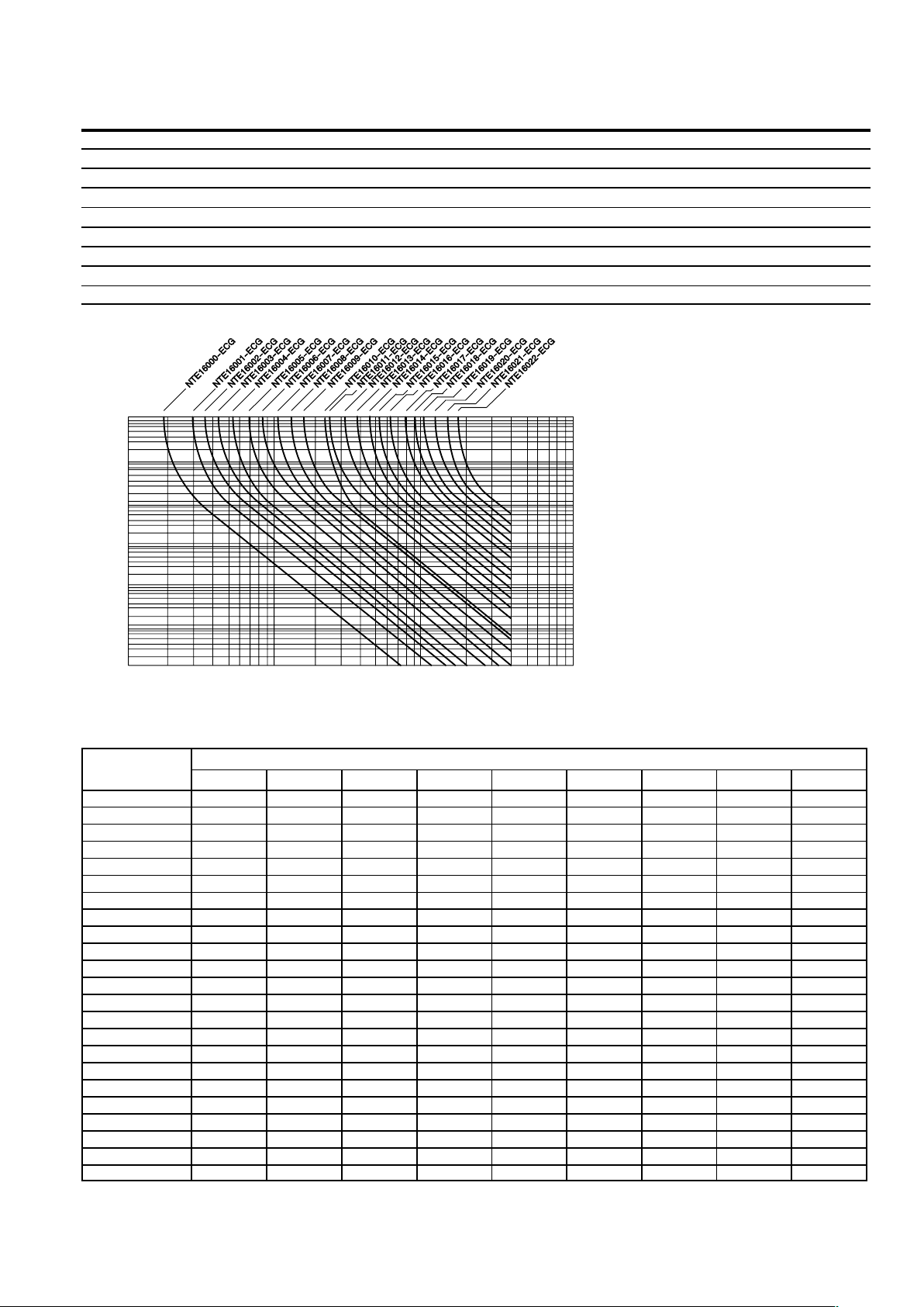
TYPICAL TIME TO TRIP AT +235
0.1 1 10 100
100
10
1
0.1
0.0
1
0.001
Fault Current (Amps)
Time to Trip (Seconds)
THERMAL DERATING CHART – I
HOLD
(Amps) *
Ambient Operating Temperature
NTE Type No.
–405C –205C 05C +235C +405C +505C +605C +705C +855C
NTE16000–ECG 0.16 0.14 0.12 0.10 0.08 0.07 0.06 0.05 0.04
NTE16001–ECG 0.26 0.23 0.20 0.17 0.14 0.12 0.11 0.09 0.07
NTE16002–ECG 0.31 0.27 0.24 0.20 0.16 0.14 0.13 0.11 0.08
NTE16003–ECG 0.39 0.34 0.30 0.25 0.20 0.18 0.16 0.14 0.10
NTE16004–ECG 0.47 0.41 0.36 0.30 0.24 0.22 0.19 0.16 0.12
NTE16005–ECG 0.62 0.54 0.48 0.40 0.32 0.29 0.25 0.22 0.16
NTE16006–ECG 0.78 0.68 0.60 0.50 0.41 0.36 0.32 0.27 0.20
NTE16007–ECG 1.01 0.88 0.77 0.65 0.53 0.47 0.41 0.35 0.26
NTE16008–ECG 1.16 1.02 0.89 0.75 0.61 0.54 0.47 0.41 0.30
NTE16009–ECG 1.40 1.22 1.07 0.90 0.73 0.65 0.57 0.49 0.36
NTE16010–ECG 1.40 1.22 1.07 0.90 0.73 0.65 0.57 0.49 0.36
NTE16011–ECG 1.60 1.43 1.27 1.10 0.91 0.85 0.75 0.67 0.57
NTE16012–ECG 1.96 1.76 1.55 1.35 1.12 1.04 0.92 0.82 0.70
NTE16013–ECG 2.32 2.08 1.84 1.60 1.33 1.23 1.09 0.98 0.83
NTE16014–ECG 2.68 2.41 2.13 1.85 1.54 1.42 1.26 1.13 0.96
NTE16015–ECG 3.63 3.25 2.88 2.50 2.08 1.93 1.70 1.53 1.30
NTE16016–ECG 4.35 3.90 3.45 3.00 2.49 2.31 2.04 1.83 1.56
NTE16017–ECG 5.80 5.20 4.60 4.00 3.32 3.08 2.72 2.44 2.08
NTE16018–ECG 7.25 6.50 5.75 5.00 4.15 3.85 3.40 3.05 2.60
NTE16019–ECG 8.70 7.80 6.90 6.00 4.98 4.62 4.08 3.66 3.12
NTE16020–ECG 10.15 9.10 8.05 7.00 5.81 5.39 4.76 4.27 3.64
NTE16021–ECG 11.60 10.40 9.20 8.00 6.64 6.16 5.44 4.88 4.16
NTE16022–ECG 13.05 11.70 10.35 9.00 7.47 6.39 6.12 5.49 4.68
*I
Trip
= 2 • I
Hold
Page 3

DIMENSIONAL OUTLINE DRAWINGS
Diagram 629 Diagram 630
NOTE: Shape changes from round to square starting
with NTE16016–ECG.
A
B
C
D
E
E
A
C
B
D
PRODUCT DIMENSIONS (Dimensions are in inches(mm))
A B C D E Physical Characteristice
NTE Type No.
Max. Max. Nom. Tol. + Min. Max. Diag. No. Lead Dia. Material
NTE16000–ECG .290 (7.4) .500 (12.7) .200 (5.1) .027 (0.7) .300 (7.6) .122 (3.1) 629 .020 (0.51) Sn/NiCu
NTE16001–ECG .290 (7.4) .500 (12.7) .200 (5.1) .027 (0.7) .300 (7.6) .122 (3.1) 629 .020 (0.51) Sn/CuFe
NTE16002–ECG .290 (7.4) .500 (12.7) .200 (5.1) .027 (0.7) .300 (7.6) .122 (3.1) 629 .020 (0.51) Sn/CuFe
NTE16003–ECG .290 (7.4) .500 (12.7) .200 (5.1) .027 (0.7) .300 (7.6) .122 (3.1) 629 .020 (0.51) Sn/CuFe
NTE16004–ECG .290 (7.4) .530 (13.4) .200 (5.1) .027 (0.7) .300 (7.6) .122 (3.1) 629 .020 (0.51) Sn/CuFe
NTE16005–ECG .290 (7.4) .540 (13.7) .200 (5.1) .027 (0.7) .300 (7.6) .122 (3.1) 629 .020 (0.51) Sn/CuFe
NTE16006–ECG .310 (7.9) .540 (13.7) .200 (5.1) .027 (0.7) .300 (7.6) .122 (3.1) 629 .020 (0.51) Sn/Cu
NTE16007–ECG .380 (9.7) .600 (15.2) .200 (5.1) .027 (0.7) .300 (7.6) .122 (3.1) 629 .020 (0.51) Sn/Cu
NTE16008–ECG .410 (10.4) .630 (16.0) .200 (5.1) .027 (0.7) .300 (7.6) .122 (3.1) 629 .020 (0.51) Sn/Cu
NTE16009–ECG .460 (11.7) .660 (16.7) .200 (5.1) .027 (0.7) .300 (7.6) .122 (3.1) 629 .020 (0.51) Sn/Cu
NTE16010–ECG .290 (7.4) .480 (12.2) .200 (5.1) .027 (0.7) .300 (7.6) .120 (3.0) 630 .020 (0.51) Sn/Cu
NTE16011–ECG .350 (8.9) .550 (14.0) .200 (5.1) .027 (0.7) .300 (7.6) .120 (3.0) 629 .020 (0.51) Sn/Cu
NTE16012–ECG .350 (8.9) .750 (18.9) .200 (5.1) .027 (0.7) .300 (7.6) .120 (3.0) 629 .020 (0.51) Sn/Cu
NTE16013–ECG .400 (10.2) .660 (16.8) .200 (5.1) .027 (0.7) .300 (7.6) .120 (3.0) 629 .020 (0.51) Sn/Cu
NTE16014–ECG .470 (12.0) .720 (18.4) .200 (5.1) .027 (0.7) .300 (7.6) .120 (3.0) 629 .020 (0.51) Sn/Cu
NTE16015–ECG .470 (12.0) .720 (18.3) .200 (5.1) .027 (0.7) .300 (7.6) .120 (3.0) 630 .030 (0.81) Sn/Cu
NTE16016–ECG .470 (12.0) .720 (18.3) .200 (5.1) .027 (0.7) .300 (7.6) .120 (3.0) 630 .030 (0.81) Sn/Cu
NTE16017–ECG .570 (14.4) .970 (24.8) .200 (5.1) .027 (0.7) .300 (7.6) .120 (3.0) 630 .030 (0.81) Sn/Cu
NTE16018–ECG .690 (17.4) .980 (24.9) .400 (10.2) .027 (0.7) .300 (7.6) .120 (3.0) 630 .030 (0.81) Sn/Cu
NTE16019–ECG .760 (19.3) 1.260 (31.9) .400 (10.2) .027 (0.7) .300 (7.6) .120 (3.0) 630 .030 (0.81) Sn/Cu
NTE16020–ECG .870 (22.1) 1.170 (29.8) .400 (10.2) .027 (0.7) .300 (7.6) .120 (3.0) 630 .030 (0.81) Sn/Cu
NTE16021–ECG .960 (24.2) 1.300 (32.9) .400 (10.2) .027 (0.7) .300 (7.6) .120 (3.0) 630 .030 (0.81) Sn/Cu
NTE16022–ECG .960 (24.2) 1.300 (32.9) .400 (10.2) .027 (0.7) .300 (7.6) .120 (3.0) 630 .030 (0.81) Sn/Cu
Page 4

RESETTABLE CIRCUIT PROTECTION
When it comes to Polymeric Positive Temperature
Coefficient (PPTC) circuit protection, you now have a
choice.
Polymeric fuses are made from a conductive plastic
formed into thin sheets, with electrodes attached to either
side. The conductive plastic is manufactured from a non–
conductive crystalline polymer and a highly conductive
carbon balck. The electrodes ensure even distribution of
power through the device, and provide a surface for leads
to be attached or for custom mounting.
The phenomenon that allows conductive plastic materials to be used for resettable overcurrent protection devices is that they exhibit a very large non–linear Positive
Temperature Coefficient (PTC) effect when heated. PTC
is a characteristic that many materials exhibit whereby resistance increases with temperature. What makes the
polymeric conductive plastic material unique is the magnitude of its resistance increase. At a specific transition temperature, the increase is resistance is so great that it is typically expressed on a log scale.
HOW POLYMERIC RESETTABLE
OVERCURRENT PROTECTORS WORK
The conductive carbon black filler material in the polymeric device is dispersed in a polymer that has a crystalline structure. The crystalline structure densely packs the
carbon particles into its crystalline boundry so they are
close enough together to allow current to flow through the
polymer insulator via these carbon “chains”.
When the conductive plastic material is at normal room
temperature, there are numerous carbon chains forming
conductive paths through the material.
Under fault conditions, excessive current flows through
the polymeric device. I
2
R heating causes the conductive
plastic material’s temperature to rise. As this self heating
continues, the material’s temperature continues to rise
until it exceeds its phase transformation temperature. As
the material passes through this phase transformation
temperature, the densely packed crystalline polymer matrix changes to an amorphous structure. This phase
change is accompanied by a small expansion. As the conductive particles move apart from each other, most of
them no longer conduct current and the resistance of the
device increases sharply.
0 20 40 60 80 100 120 140
TEMPERATURE °C
10
1
10
0
10
2
10
3
10
4
10
5
10
6
10
7
LOG R OHMS
The material will stay “hot”, remaining in this high resistance state as long as the power is applied. The device will
remain latched, providing continuous protection, until the
fault is cleared and the power is removed. Reversing the
phase transformation allows the carbon chains to re–form
as the polymer re–crystallizes. The resistance quickly re-
turns to its original value.
PRODUCT SELECTION
To select the correct polymeric circuit protection device,
complete the imformation listed below for application, and
then refer to thwe resettable overcurrent protector data
sheets.
1. Determine the nromal operating current:
__________ amps
2. Determine the maximum circuit voltage (V
max
):
__________ volts
3. Determine the fault current (I
max
):
__________ amps
4. Determine the operating temperature range:
Minimum Temperature: __________ °C
Maximum Temperature: __________ °C
5. Select a product family so that the maximum rating for
V
max
and I
max
is higher than the maximum circuit volt-
age and fault current in the application.
6. Using the I
Hold
vs. Temperature Table on the product
family data sheet, select the polymeric device at the
maximum operating temperature with an I
Hold
greater
than or equal to the normal operating current.
7. Verify that the selected device will trip under fault conditions by checking in the I
Trip
table that the fault cur-
rent is greater than I
Trip
for the selected device, at the
lowest operating temperature.
8. Order samples and test in application.
APPLICATIONS
The benefits of polymeric Resettable Overcurrent Protectors are being recognized by more and more design
engineers, and new applications are being discovered every day.
The use of polymeric types of devices have been widely
accepted in the following applications and industries:
D Personal computers
D Laptop computers
D Personal digital assistants
D Transformers
D Small and medium electric motors
D Audio equipment and speakers
D Test and measurement equipment
D Security and fire alarm systems
D Personal care products
D Point–of–sale equipment
D Industrial controls
D Automotive electronics and harness protection
D Marine electronics
D Battery–operated toys
 Loading...