

Page 1

DATA SHEET
N-CHANNEL GaAs MESFET
NEZ1011-2E, NEZ1414-2E
2W X, Ku-BAND POWER GaAs MESFET
DESCRIPTION
The NEZ1011-2E and NEZ1414-2E are power GaAs MESFETs which provide high gain, high efficiency and high
output in X, Ku-band. The internal input and output matching enables guaranteed performance to be achieved with
only a 50 Ω external circuit. To reduce thermal resistance the device has a PHS (Plated Heat Sink) structure. The
device incorporates a WSi (tungsten silicide) gate structure for high reliability.
FEATURES
• High Output Power : P
• High Linear Gain : 8.5 dB typ. (NEZ1011-2E), 7.5 dB typ. (NEZ1414-2E)
• High Efficiency : 30 % typ.
• Input and Output Internally Matched for Optimum performance
o (1 dB)
= +34.0 dBm typ.
ORDERING INFORMATION
Part Number Package
NEZ1011-2E
NEZ1414-2E
Remark
To order evaluation samples, please contact your local NEC sales office.
T-78
(Part number for sample order: NEZ1011-2E, NEZ1414-2E)
ABSOLUTE MAXIMUM RATINGS (TA = 25°C)
Operation in excess of any one of these parameters may result in permanent damage.
Parameter Symbol Ratings Unit
Drain to Source Voltage V
Gate to Source Voltage V
Drain Current I
Gate Forward Current I
Gate Reverse Current I
Total Power Dissipat i on P
Channel Temperature T
Storage Temperature T
DS
GS
DS
GF
GR
T
ch
stg
15 V
–7 V
3.0 (NEZ1011-2E)
2.5 (NEZ1414-2E)
+20 mA
–20 mA
15 W
175 °C
–65 to +175 °C
A
Caution Please handle this device at static-free workstation, because this is an electrostatic sensitive
device.
Document No. P13725EJ1V0DS00 (1st edition)
Date Published September 1998 N CP(K)
Printed in Japan
The information in this document is subject to change without notice.
1998©
Page 2

RECOMMENDED OPERATING LIMITS
Characteristics Symbol Test Condition MIN. TYP. MAX. Unit
NEZ1011-2E, NEZ1414-2E
Drain to Source Voltage V
DS
9.0 9.0 9.0 V
Gain Compression Gcomp 3 dB
Channel Temperature T
Gate Resistance
Note
Note
g
R
is the series resistance between the gate supply and the FET gate.
ch
g
R
200 1000 1000 Ω
+130 °C
[NEZ1011-2E]
A
ELECTRICAL CHARACTERISTICS (T
Characteristics Symbol Test Conditions MIN. TYP. MAX. Unit
BV
o (1 dB)
P
DS (1 dB)
I
add (1 dB)
η
IM
DSS
p
GD
th
L
3
Saturated Drain Current I
Pinch-off Voltage V
Gate to Drain Breakdown Voltage
Thermal Resistance R
Linear Gain G
Output Power at 1 dB Gain Comp.
Drain Current at 1 dB Gain Comp.
Power Added Efficiency at 1 dB
Gain Compression Point
3rd Order Intermodulation
Distortion
= 25°C)
VDS = 1.5 V, VGS = 0 V 0.7 1.6 2.5 A
VDS = 2.5 V, IDS = 10 mA –2.5 –1.3 –0.5 V
IGD = 10 mA 15 V
Channel to Case 5.5 7.0 °C/W
f = 10.7, 11.2, 11.7 GHz
DS
= 9.0 V
V
DS
= 0.7 A (RF OFF)
I
g
= 1 kΩ
R
out
P
= +27.5 dBm (2 tone) –40 dBc
8.0 8.5 dB
33.0 34.0 dBm
0.8 1.0 A
30 %
[NEZ1414-2E]
ELECTRICAL CHARACTERISTICS (T
Characteristics Symbol Test Conditions MIN. TYP. MAX. Unit
BV
o (1 dB)
P
DS (1 dB)
I
add (1 dB)
η
DSS
p
GD
th
L
Saturated Drain Current I
Pinch-off Voltage V
Gate to Drain Breakdown Voltage
Thermal Resistance R
Linear Gain G
Output Power at 1 dB Gain Comp.
Drain Current at 1 dB Gain Comp.
Power Added Efficiency at 1 dB
Gain Compression Point
2
A
= 25°C)
VDS = 1.5 V, VGS = 0 V 0.7 1.6 3.0 A
VDS = 2.5 V, IDS = 10 mA –3.0 –1.3 –0.5 V
IGD = 10 mA 15 V
Channel to Case 5.5 7.0 °C/W
f = 14.0 to 14.5 GHz
DS
= 9.0 V
V
DS
= 0.7 A (RF OFF)
I
g
= 1 kΩ
R
7.0 7.5 dB
33.0 34.0 dBm
0.8 1.0 A
30 %
Page 3

[NEZ1011-2E] TYPICAL CHARACTERISTICS (TA = 25°C)
OUTPUT POWER, DRAIN CURRENT AND EFFICIENCY
vs. INPUT POWER
+35
NEZ1011-2E, NEZ1414-2E
80
P
out
70
60
+30
- Output Power - dBm
out
P
+25
+20
add
η
+20 +25 +30
Pin - Input Power - dBm TEST CONDITIONS
ds
V
I
ds
50
40
- Efficiency - %
add
30
η
20
10
0
: 9.0 (V)
: 0.7 (A)
3
Page 4

[NEZ1011-2E] TYPICAL S-PARAMETERS
Vds = 9.0 V, Ids = 0.7 A Marker
START 9.5 GHz, STOP 13 GHz, STEP 100 MHz 1: 10.7 GHz
2: 11.7 GHz
S
11
NEZ1011-2E, NEZ1414-2E
S
12
1.0
0.5
2.0
1
0
2
–0.5
–2.0
–1.0
R
max
S
21
+90°
+135° +45°
1
= 1
+90°
+135° +45°
1
∞
±180° 0°
2
–135°
–45°
–90°
max
= 0.25
R
S
22
1.0
0.5
2.0
±180° 0°
2
–135°
–45°
–90°
max
R
4
= 5
1
0
–0.5
2
–2.0
∞
–1.0
max
= 1
R
Page 5

[NEZ1011-2E] TYPICAL S-PARAMETERS
MAG. AND ANG.
Vds = 9.0 V, Ids = 0.7 A
NEZ1011-2E, NEZ1414-2E
0.764
0.761
0.758
0.753
0.746
0.736
0.722
0.706
0.686
0.668
0.645
0.624
0.598
0.578
0.554
0.528
0.507
0.478
0.456
0.422
0.394
0.358
0.318
0.279
0.240
0.209
0.200
0.212
0.252
0.309
0.361
0.416
0.469
0.519
0.559
0.597
11
(deg.) (deg.) (deg.) (deg.)
–167.277
–178.028
171.529
160.103
148.570
136.528
124.575
112.284
100.666
89.224
77.773
67.151
56.412
46.466
36.030
26.451
16.580
6.600
–3.277
–13.834
–24.217
–36.871
–49.672
–65.213
–84.430
–107.600
–138.676
–167.414
166.906
147.122
131.557
118.401
107.640
98.604
89.444
81.722
FREQUENCY S
GHz MAG.ANG.MAG.ANG.MAG.ANG.MAG.ANG.
9.50
9.60
9.70
9.80
9.90
10.0
10.1
10.2
10.3
10.4
10.5
10.6
10.7
10.8
10.9
11.0
11.1
11.2
11.3
11.4
11.5
11.6
11.7
11.8
11.9
12.0
12.1
12.2
12.3
12.4
12.5
12.6
12.7
12.8
12.9
13.0
0.015
0.016
0.016
0.017
0.021
0.024
0.028
0.032
0.035
0.040
0.044
0.050
0.054
0.059
0.062
0.066
0.070
0.074
0.075
0.079
0.084
0.086
0.096
0.096
0.100
0.105
0.097
0.103
0.098
0.095
0.105
0.097
0.102
0.106
0.082
0.088
12
S
–43.230
–65.634
–91.498
–118.516
–141.838
–171.701
167.511
144.823
121.478
105.970
87.091
70.741
54.078
37.806
21.296
6.098
–7.465
–22.940
–35.751
–49.149
–63.862
–77.583
–92.366
–107.789
–123.743
–138.506
–155.009
–170.320
175.893
160.769
143.930
131.537
116.588
99.572
84.259
66.604
2.130
2.340
2.425
2.517
2.750
2.799
2.790
2.912
2.927
2.942
2.970
2.970
2.945
2.944
2.917
2.906
2.920
2.902
2.889
2.933
2.901
2.874
2.890
2.905
2.857
2.845
2.824
2.638
2.617
2.572
2.409
2.256
2.162
2.023
1.844
1.863
21
S
–95.531
–111.739
–123.950
–134.894
–151.673
–167.695
176.393
161.709
146.204
131.119
116.345
101.187
86.551
72.072
57.262
43.390
29.090
14.522
0.451
–14.070
–29.339
–43.606
–56.908
–73.786
–89.725
–105.536
–120.676
–138.590
–153.421
–167.311
174.881
158.493
143.945
130.613
116.717
102.174
0.635
0.611
0.584
0.553
0.516
0.476
0.432
0.388
0.344
0.299
0.260
0.229
0.208
0.200
0.202
0.212
0.222
0.237
0.248
0.256
0.264
0.265
0.262
0.257
0.246
0.233
0.214
0.193
0.174
0.160
0.155
0.163
0.183
0.211
0.246
0.287
22
S
–83.968
–91.286
–98.187
–106.003
–114.652
–123.658
–133.644
–145.015
–157.688
–172.088
171.488
152.876
131.672
109.753
89.248
70.797
54.193
39.808
26.634
14.662
–8.418
–19.614
–31.209
–43.300
–55.965
–71.338
–87.955
–107.656
–130.767
–155.714
178.469
155.527
135.870
119.252
104.110
3.065
5
Page 6

[NEZ1414-2E] TYPICAL CHARACTERISTICS (TA = 25°C)
OUTPUT POWER, DRAIN CURRENT AND EFFICIENCY
vs. INPUT POWER
NEZ1011-2E, NEZ1414-2E
+35
+30
Pout - Output Power - dBm
+25
+20
+20 +25 +30
Pout
add
η
Pin - Input Power - dBm TEST CONDITIONS
80
70
60
50
40
30
20
10
0
ds
V
Ids
add - Efficiency - %
η
: 9.0 (V)
: 0.7 (A)
6
Page 7

[NEZ1414-2E] TYPICAL S-PARAMETERS
Vds = 9.0 V, Ids = 0.7 A Marker
START 12.5 GHz, STOP 16 GHz, STEP 100 MHz 1: 14.0 GHz
2: 14.5 GHz
S
11
NEZ1011-2E, NEZ1414-2E
S
12
1.0
0.5
0
2
2.0
1
–0.5
–2.0
–1.0
R
max
S
21
+90°
+135° +45°
2
1
= 1
+90°
+135° +45°
1
∞
±180° 0°
–135°
2
–45°
–90°
R
max
= 0.25
S
22
1.0
0.5
2.0
±180° 0°
–135°
–45°
–90°
R
max
= 5
1
0
–0.5
2
–2.0
∞
–1.0
max
= 1
R
7
Page 8

[NEZ1414-2E] TYPICAL S-PARAMETERS
MAG. AND ANG.
Vds = 9.0 V, Ids = 0.7 A
NEZ1011-2E, NEZ1414-2E
0.720
0.714
0.703
0.694
0.681
0.665
0.647
0.619
0.598
0.564
0.528
0.489
0.458
0.417
0.379
0.345
0.316
0.299
0.283
0.286
0.294
0.316
0.341
0.371
0.404
0.434
0.470
0.500
0.535
0.563
0.592
0.614
0.643
0.667
0.693
0.714
11
(deg.) (deg.) (deg.) (deg.)
54.026
47.272
40.563
33.714
25.911
18.142
10.006
1.522
–7.303
–16.994
–25.513
–35.940
–46.827
–58.735
–71.139
–86.020
–100.664
–117.676
–135.202
–153.247
–171.013
172.686
157.476
143.634
130.878
119.410
107.612
96.950
86.060
75.185
64.542
54.164
43.880
33.519
24.111
14.872
FREQUENCY S
GHz MAG.ANG.MAG.ANG.MAG.ANG.MAG.ANG.
12.5
12.6
12.7
12.8
12.9
13.0
13.1
13.2
13.3
13.4
13.5
13.6
13.7
13.8
13.9
14.0
14.1
14.2
14.3
14.4
14.5
14.6
14.7
14.8
14.9
15.0
15.1
15.2
15.3
15.4
15.5
15.6
15.7
15.8
15.9
16.0
0.041
0.042
0.046
0.054
0.042
0.049
0.048
0.050
0.065
0.066
0.078
0.076
0.094
0.083
0.104
0.098
0.095
0.100
0.094
0.096
0.098
0.099
0.103
0.108
0.107
0.113
0.104
0.102
0.099
0.091
0.093
0.089
0.089
0.085
0.081
0.076
12
S
–23.488
–33.909
–49.053
–67.659
–75.730
–91.627
–106.322
–123.298
–121.906
–147.244
–144.394
–164.810
174.594
160.842
137.769
123.598
110.275
95.196
85.165
73.113
56.700
46.372
29.217
13.049
0.943
–17.401
–31.285
–45.363
–59.856
–74.474
–86.447
–101.479
–115.807
–129.917
–143.437
–159.317
1.670
1.618
1.805
1.905
1.883
2.076
2.139
2.226
2.244
2.269
2.572
2.705
2.394
2.514
2.483
2.337
2.380
2.475
2.473
2.387
2.393
2.363
2.329
2.311
2.279
2.226
2.173
2.138
2.067
2.002
1.930
1.858
1.768
1.668
1.558
1.473
21
S
–12.914
–27.927
–33.613
–41.620
–59.438
–70.774
–85.459
–106.292
–117.709
–129.798
–146.964
–157.354
–172.475
172.741
160.220
143.589
130.321
115.146
100.169
85.738
72.248
58.619
44.378
30.331
15.402
0.717
–13.915
–28.618
–43.793
–58.791
–74.024
–88.826
–104.195
–119.138
–134.157
–148.375
0.559
0.536
0.513
0.489
0.469
0.444
0.423
0.397
0.376
0.354
0.331
0.308
0.291
0.267
0.245
0.222
0.199
0.177
0.155
0.132
0.113
0.092
0.074
0.059
0.048
0.046
0.054
0.068
0.087
0.109
0.134
0.162
0.197
0.231
0.268
0.311
22
S
139.492
132.577
125.731
118.906
110.831
102.528
94.278
85.041
76.035
66.079
56.921
46.382
35.057
23.990
12.747
0.830
–10.034
–21.527
–33.131
–45.132
–57.855
–72.397
–89.862
–113.198
–143.105
–178.465
147.862
121.138
100.050
81.796
65.785
51.196
38.392
26.433
15.119
5.747
8
Page 9
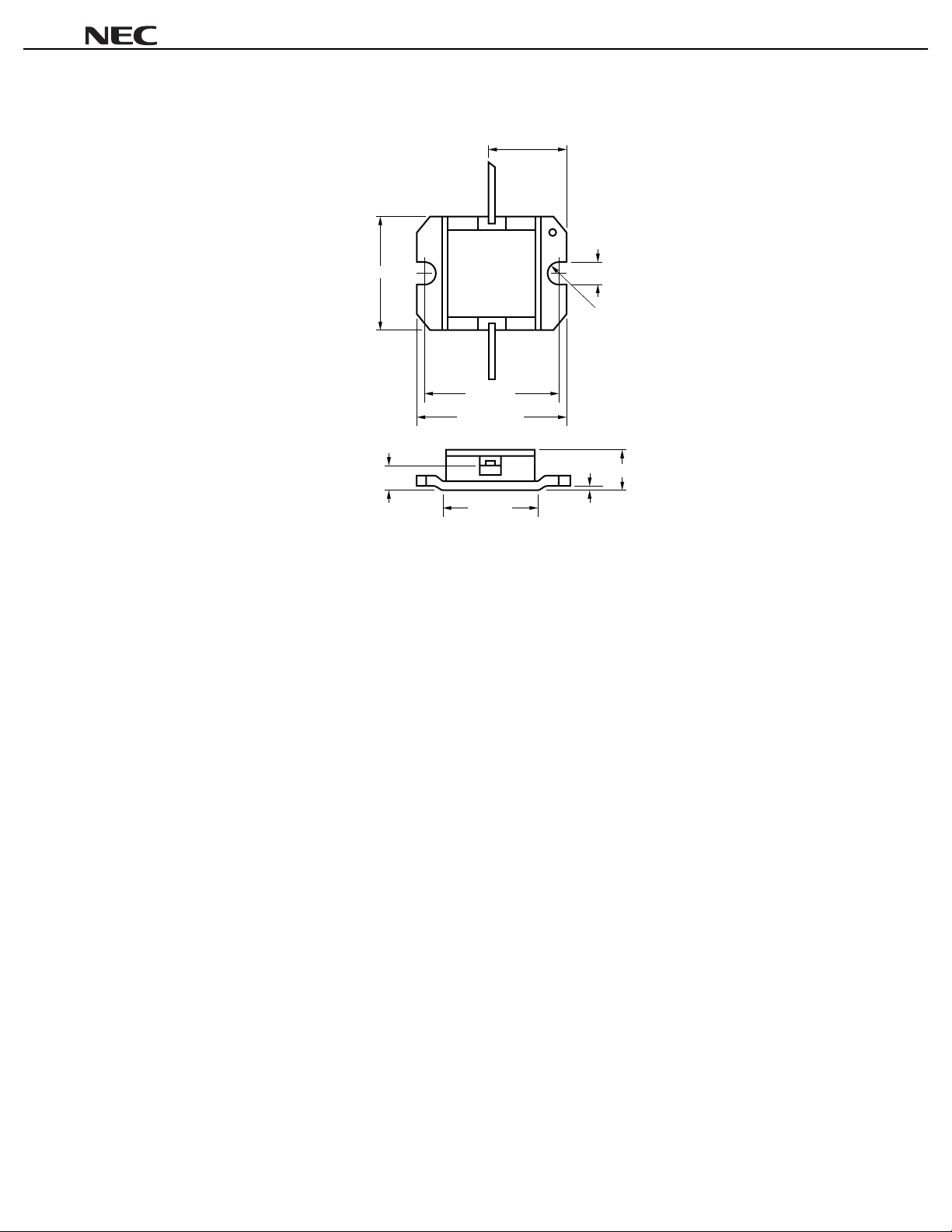
PACKAGE DIMENSIONS (UNIT: mm)
NEZ1011-2E, NEZ1414-2E
8.25 ±0.15
Gate
Source
9.7 ±0.13
1.8 ±0.1
Drain
13 ±0.1
16.5 ±0.13
9 ±0.3
2.74 ±0.1
R 0.65
3.0 ±0.2
0.2 MAX.
9
Page 10

NEZ1011-2E, NEZ1414-2E
RECOMMENDED SOLDERING CONDITIONS
This product should be soldered under the following recommended conditions. For soldering methods and
conditions other than those recommended below, contact your NEC sales representative.
Soldering Method Soldering Conditions Recommended Condition Symbol
Partial Heating Pin temperature: 260°C
Time: 5 seconds or less (per pi n row)
For details of recommended soldering conditions, please contact your local NEC sales office.
–
10
Page 11

[MEMO]
NEZ1011-2E, NEZ1414-2E
11
Page 12

NEZ1011-2E, NEZ1414-2E
Caution
The Great Care must be taken in dealing with the devices in this guide.
The reason is that the material of the devices is GaAs (Gallium Arsenide), which is
designated as harmful substance according to the law concerned.
Keep the law concerned and so on, especially in case of removal.
No part of this document may be copied or reproduced in any form or by any means without the prior written
consent of NEC Corporation. NEC Corporation assumes no responsibility for any errors which may appear in this
document.
NEC Corporation does not assume any liability for infringement of patents, copyrights or other intellectual
property rights of third parties by or arising from use of a device described herein or any other liability arising
from use of such device. No license, either express, implied or otherwise, is granted under any patents,
copyrights or other intellectual property rights of NEC Corporation or others.
While NEC Corporation has been making continuous effort to enhance the reliability of its semiconductor devices,
the possibility of defects cannot be eliminated entirely. To minimize risks of damage or injury to persons or
property arising from a defect in an NEC semiconductor device, customers must incorporate sufficient safety
measures in its design, such as redundancy, fire-containment, and anti-failure features.
NEC devices are classified into the following three quality grades:
"Standard", "Special", and "Specific". The Specific quality grade applies only to devices developed based on
a customer designated "quality assurance program" for a specific application. The recommended applications
of a device depend on its quality grade, as indicated below. Customers must check the quality grade of each
device before using it in a particular application.
Standard: Computers, office equipment, communications equipment, test and measurement equipment,
audio and visual equipment, home electronic appliances, machine tools, personal electronic
equipment and industrial robots
Special: Transportation equipment (automobiles, trains, ships, etc.), traffic control systems, anti-disaster
systems, anti-crime systems, safety equipment and medical equipment (not specifically designed
for life support)
Specific: Aircrafts, aerospace equipment, submersible repeaters, nuclear reactor control systems, life
support systems or medical equipment for life support, etc.
The quality grade of NEC devices is "Standard" unless otherwise specified in NEC's Data Sheets or Data Books.
If customers intend to use NEC devices for applications other than those specified for Standard quality grade,
they should contact an NEC sales representative in advance.
Anti-radioactive design is not implemented in this product.
M4 96. 5
 Loading...