

Page 1
PRELIMINARY DATA SHEET
NE6500496
4 W L, S-BAND POWER GaAs FET
N-CHANNEL GaAs MES FET
GaAs MES FET
DESCRIPTION
The NE6500496 is power GaAs FET which provides high
gain, high efficiency and high output power in L, S band.
To reduce thermal resistance, the device has a PHS
(Plated Heat Sink) structure.
FEATURES
• Class A operation
• High output power: 36 dBm (typ)
• High gain: 11.5 dB (typ)
• High power added efficiency: 45 % (typ)
• Hermetically sealed ceramic package
ABSOLUTE MAXIMUM RATINGS (T
Drain to Source Voltage VDSX 15 V
Gate to Drain Voltage V
Gate to Source Voltage VGSX –12 V
Drain Current ID 4.5 A
Gate Current I
Total Power Dissipation PT(*)25 W
Channel Temperature Tch 175 ˚C
Storage Temperature T
Temperature Cycling T∞ –40 to +120 ˚C
GDX –18 V
G 25 mA
stg –65 to +175 ˚ C
A = 25 ˚C)
* TC = 25 ˚C
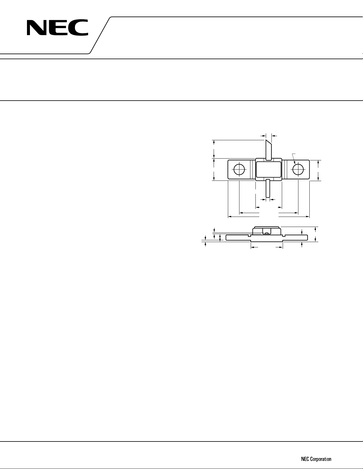
PACKAGE DIMENSION (UNIT: mm)
4.0 MIN BOTHLEADS
4.3 ±0.2
0.1
0.2 MAX.
1.7 ±0.15
SOURCE
DRAIN
0.6 ±0.1
5.2 ±0.3
11.0 ±0.3
15.0 ±0.3
6.0 ±0.2
1.0 ± 0.1
GATE
2.2 ±0.3
φ
2 SLACES
5.0 MAX.
1.2
4.0
Caution Please handle this device at a static-free workstation, because this is an electrostatic sensitive
device.
Document No. P10971EJ1V0DS00 (1st edition)
Date Published June 1996 P
Printed in Japan
©
1996
Page 2
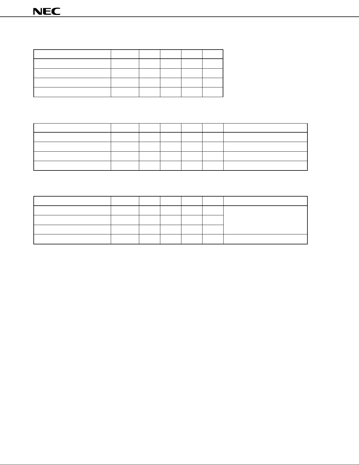
MAXIMUM OPERATION RANDGE
CHARACTERISTIC SYMBOL MIN. TYP. MAX. UNIT
Drain to Source Voltage VDS –1010V
Channel Temperature Tch – – 130 ˚C
Input Power Gcomp – – 3 dBcomp
Gate Resistance Rg – – 200 Ω
ELECTRICAL CHARACTERISTICS (TA = 25 ˚C)
CHARACTERISTIC SYMBOL MIN. TYP. MAX. UNIT TEST CONDITIONS
Saturated Drain Current Idss 1.0 2.3 3.5 A Vds = 1.5 V, Vgs = 0 V
Pinch-off Voltage VP –3.5 –2.0 –0.5 V Vds = 2.5 V, Ids = 15 mA
Transconductance gm – 1300 – mS Vds = 2.5 V, Ids = 1 A
Thermal Resistance Rth – 6.0 6.5 ˚C/W channel to case
NE6500496
PERFORMANCE SPECIFICATIONS (TA = 25 ˚C)
CHARACTERISTIC SYMBOL MIN. TYP. MAX. UNIT TEST CONDITIONS
Output Power Pout 35.5 36.0 – dBm
Gate to Source Current Igs –5 – 5 mA
Power Added Efficiency
Linear Gain GL 11.0 11.5 – dB Pin ≤ 20 dBm (*)
η
add – 45 – %
f = 2.3 GHz, Vds = 10 V
Ids ≤ 0.4 A, Pin = 26.0 dBm
Rg = 200 Ω
* The other are the same as the above conditions.
2
Page 3

TYPICAL CHARACTERISTICS (TA = 25 ˚C)
out
(dBm)
P
OUTPUT POWER vs. INPUT POWER
40
DS
= 10 V,
V
IDS = 0.4 A
37
34
NE6500496
Id (mA)
2000
P
out
1600
I
d
1200
31
- Output Power - dBm
out
P
28
25
15
18 21 24 27 30
in
P
800
400
0
- Input Power - dBm
3
Page 4

S-PARAMETER
VDS = 9.0 V, IDS = 400 mA, VGS = –1.619 V, IG = 0.0 mA
NE6500496
FREQUENCY
GHz MAG ANG MAG ANG MAG ANG MAG ANG
0.100 0.978 –80.0 17.314 137.4 0.010 60.2 0.612 –172.8
0.200 0.957 –118.9 11.458 116.5 0.015 36.4 0.667 –175.2
0.300 0.951 –137.8 8.252 105.7 0.016 30.0 0.687 –177.6
0.400 0.949 –148.5 6.388 98.8 0.016 29.0 0.695 –179.7
0.500 0.947 –155.4 5.188 93.9 0.017 29.1 0.700 178.8
0.600 0.947 –160.2 4.368 90.0 0.017 27.5 0.704 177.4
0.700 0.946 –163.9 3.769 86.6 0.017 29.5 0.705 176.2
0.800 0.946 –166.8 3.319 83.6 0.018 31.0 0.707 175.1
0.900 0.946 –169.2 2.963 80.8 0.018 32.8 0.709 174.0
1.000 0.945 –171.2 2.679 78.2 0.019 33.7 0.710 173.0
1.100 0.945 –173.1 2.438 75.5 0.020 34.9 0.711 172.2
1.200 0.946 –174.5 2.251 73.4 0.020 35.7 0.711 171.2
1.300 0.945 –175.9 2.087 71.2 0.021 36.8 0.714 170.3
1.400 0.944 –177.1 1.947 69.0 0.021 38.6 0.715 169.4
1.500 0.945 –178.2 1.828 67.0 0.022 39.5 0.716 168.5
1.600 0.944 –179.4 1.720 64.7 0.023 40.5 0.715 167.5
1.700 0.943 179.6 1.627 62.6 0.024 41.8 0.716 166.2
1.800 0.944 178.6 1.547 60.5 0.024 41.8 0.721 165.4
1.900 0.943 177.7 1.468 58.7 0.025 43.8 0.718 164.5
2.000 0.944 176.8 1.404 56.4 0.026 43.8 0.719 163.2
2.100 0.944 175.9 1.345 54.6 0.027 45.8 0.722 162.0
2.200 0.945 175.2 1.296 52.7 0.028 46.4 0.728 161.1
2.300 0.945 174.3 1.245 50.8 0.030 47.4 0.725 160.4
2.400 0.945 173.5 1.201 48.6 0.031 45.8 0.726 158.7
2.500 0.944 172.7 1.163 46.8 0.031 47.2 0.734 157.4
2.600 0.944 172.0 1.131 45.2 0.034 49.1 0.742 156.8
2.700 0.945 171.2 1.087 43.7 0.035 48.7 0.737 156.1
2.800 0.947 170.4 1.054 41.6 0.036 47.5 0.738 154.5
2.900 0.947 169.6 1.028 39.6 0.037 46.7 0.745 153.3
3.000 0.946 168.7 1.008 37.7 0.039 47.2 0.757 152.3
3.500 0.947 164.9 0.901 29.5 0.046 46.8 0.766 148.8
4.000 0.950 160.5 0.840 20.9 0.056 41.3 0.771 144.2
4.500 0.941 155.3 0.810 11.9 0.059 37.4 0.776 138.0
5.000 0.933 149.6 0.795 1.5 0.069 33.4 0.792 130.8
S11 S21 S12 S22
4
Page 5

VDS = 10.0 V, IDS = 400 mA, VGS = –1.662 V, IG = 0.0 mA
NE6500496
FREQUENCY
GHz MAG ANG MAG ANG MAG ANG MAG ANG
0.100 0.975 –80.1 17.360 137.5 0.011 55.3 0.601 –172.5
0.200 0.956 –118.9 11.506 116.5 0.015 39.8 0.657 –175.0
0.300 0.951 –137.7 8.292 105.6 0.016 30.2 0.678 –177.5
0.400 0.949 –148.4 6.420 98.7 0.016 28.9 0.687 –179.5
0.500 0.947 –155.3 5.212 93.8 0.017 26.7 0.692 178.9
0.600 0.946 –160.1 4.388 89.8 0.017 26.5 0.695 177.7
0.700 0.946 –163.8 3.786 86.4 0.018 28.9 0.697 176.4
0.800 0.945 –166.8 3.333 83.4 0.018 30.9 0.698 175.3
0.900 0.945 –169.1 2.977 80.5 0.018 32.2 0.700 174.2
1.000 0.945 –171.2 2.691 77.9 0.019 32.4 0.702 173.3
1.100 0.944 –173.1 2.448 75.2 0.020 32.7 0.703 172.4
1.200 0.945 –174.5 2.260 73.0 0.020 35.5 0.703 171.4
1.300 0.944 –175.8 2.096 70.8 0.021 36.6 0.706 170.5
1.400 0.943 –177.1 1.955 68.6 0.021 37.8 0.708 169.7
1.500 0.944 –178.2 1.834 66.5 0.022 38.5 0.708 168.9
1.600 0.943 –179.4 1.726 64.2 0.022 40.0 0.707 167.8
1.700 0.943 179.6 1.632 62.1 0.024 41.6 0.710 166.6
1.800 0.943 178.6 1.552 60.0 0.024 41.7 0.714 165.7
1.900 0.943 177.7 1.474 58.1 0.025 44.3 0.711 164.9
2.000 0.944 176.8 1.408 55.8 0.026 43.4 0.712 163.5
2.100 0.943 176.0 1.348 53.9 0.027 45.6 0.716 162.4
2.200 0.945 175.2 1.299 52.0 0.028 46.1 0.721 161.5
2.300 0.944 174.3 1.248 50.2 0.030 47.1 0.719 160.8
2.400 0.944 173.5 1.203 48.0 0.031 46.0 0.720 159.1
2.500 0.944 172.7 1.166 46.2 0.031 46.0 0.728 157.9
2.600 0.944 171.9 1.132 44.5 0.033 47.5 0.736 157.2
2.700 0.945 171.2 1.089 42.9 0.034 48.6 0.733 156.6
2.800 0.946 170.4 1.055 40.8 0.036 46.6 0.732 155.0
2.900 0.947 169.6 1.029 38.9 0.037 46.8 0.741 153.7
3.000 0.945 168.7 1.008 36.9 0.039 46.7 0.753 152.9
3.500 0.947 165.0 0.901 28.7 0.046 47.0 0.761 149.2
4.000 0.950 160.5 0.838 20.0 0.056 41.3 0.769 144.6
4.500 0.940 155.3 0.806 10.9 0.059 37.3 0.775 138.6
5.000 0.933 149.6 0.792 0.4 0.068 34.0 0.791 131.2
S11 S21 S12 S22
5
Page 6

NE6500496
No part of this document may be copied or reproduced in any form or by any means without the prior written
consent of NEC Corporation. NEC Corporation assumes no responsibility for any errors which may appear in this
document.
NEC Corporation does not assume any liability for infringement of patents, copyrights or other intellectual
property rights of third parties by or arising from use of a device described herein or any other liability arising
from use of such device. No license, either express, implied or otherwise, is granted under any patents,
copyrights or other intellectual property rights of NEC Corporation or others.
While NEC Corporation has been making continuous effort to enhance the reliability of its semiconductor devices,
the possibility of defects cannot be eliminated entirely. To minimize risks of damage or injury to persons or
property arising from a defect in an NEC semiconductor device, customer must incorporate sufficient safety
measures in its design, such as redundancy, fire-containment, and anti-failure features.
NEC devices are classified into the following three quality grades:
“Standard“, “Special“, and “Specific“. The Specific quality grade applies only to devices developed based on
a customer designated “quality assurance program“ for a specific application. The recommended applications
of a device depend on its quality grade, as indicated below. Customers must check the quality grade of each
device before using it in a particular application.
Standard: Computers, office equipment, communications equipment, test and measurement equipment,
audio and visual equipment, home electronic appliances, machine tools, personal electronic
equipment and industrial robots
Special: Transportation equipment (automobiles, trains, ships, etc.), traffic control systems, anti-disaster
systems, anti-crime systems, safety equipment and medical equipment (not specifically designed
for life support)
Specific: Aircrafts, aerospace equipment, submersible repeaters, nuclear reactor control systems, life
support systems or medical equipment for life support, etc.
The quality grade of NEC devices in “Standard“ unless otherwise specified in NEC's Data Sheets or Data Books.
If customers intend to use NEC devices for applications other than those specified for Standard quality grade,
they should contact NEC Sales Representative in advance.
Anti-radioactive design is not implemented in this product.
M4 94.11
2
 Loading...