

Page 1
Isolated 2W Wide Input Single Output DC-DC Converters
SELECTION GUIDE
NDL SERIES
FEATURES
■ 2:1 Wide Range Voltage Input
■ Continuous Short Circuit Protection
with Current Foldback
■ Operating Temperature Range
–40°C to 85°C
■ 0.5% Regulation
■ 1kVDC Isolation
■ Efficiency to 83%
■ 5V, 12V, 24V & 48V Nominal Input
■ 5V, 9V, 12V & 15V Output
■ Power Density 0.9W/cm
3
■ External Control
■ No Electrolytic Capacitors
■ Low Noise
■ Fully Encapsulated
DESCRIPTION
The NDL series is a range of high
performance miniature DC-DC converters
having regulated outputs over the wide
temperature range of –40°C to 85°C. The
input voltage range is 2:1 with the output
power at 2 watts and the input to output
isolation is 1kVDC. Continuous short circuit
protection, external control and extremely
small SIP packaging provide state of the art
functionality. The use of ceramic capacitors
and a ceramic substrate, with a tough chip
and wire bonded MOSFET power transistor
die and SMD construction, provide genuine
high reliability. Nominal input voltages of
5,12,24 and 48V with output voltages of
5,9,12 and 15V are available as standard
with custom parts on request. The plastic case
is rated to UL 94V-0 with encapsulant to UL
94V-1. Connection pins are phosphor bronze
with a 60/40 tin lead solder dipped finish.
www.dc-dc.com
Nominal Rated
Input Output
Voltage Voltage Min Load3Full Load Full Load MTTF
Output Current
1
Input
Current
2
Order Code (V) (V) (mA) (mA) (mA) (%) (pF) kHrs
NDL0505S
NDL0509S
NDL0512S
NDL0515S
NDL1205S
NDL1209S
NDL1212S
NDL1215S
NDL2405S
NDL2409S
NDL2412S
NDL2415S
NDL4805S
NDL4809S
NDL4812S
NDL4815S
5 5 100 400 606 66 26 2015
5 9 55 222 558 71 27 1998
5 12 42 167 559 71 26 1980
5 15 33 134 549 73 27 1965
12 5 100 400 228 73 39 1994
12 9 55 222 211 79 38 1981
12 12 42 167 208 80 47 1961
12 15 33 134 206 81 47 1947
24 5 100 400 112 74 37 1722
24 9 55 222 102 81 40 1711
24 12 42 167 100 81 51 1696
24 15 33 134 100 83 58 1685
48 5 100 400 57 73 39 1719
48 9 55 222 52 80 40 1709
48 12 42 167 51 81 53 1694
48 15 33 134 51 82 65 1683
INPUT CHARACTERISTICS
Parameter Conditions MIN TYP MAX Units
All NDL05 Types 4.5 5 9
Voltage Range
All NDL12 Types 9 12 18
All NDL24 Types 18 24 36
VDC
All NDL48 Types 36 48 72
All NDL05 types when 100µF at input 250
Reflected
Ripple
Current
All NDL12 types when 100µF at input 150
All NDL24 types when 10µF at input 300 380
All NDL48 types when 10µF at input 140 170
mA p-p
OUTPUT CHARACTERISTICS
Parameter Conditions
All NDL 05/12 types with external
Voltage Set
Point Accuracy
Line Regulation
input/output capacitors
All NDL 24/48 types with external
input/output capacitors
All NDL 05/12 types, Low line to high line,
With external input/output capacitors
All NDL 24/48 types, Low line to high l i n e ,
With external input/output capacitors
All NDL 05/12 types, Minimum load to rated load,
Load Regulation
Ripple
Noise
With external input/output capacitors
All NDL 24/48 types, Minimum load to rated load,
With external input/output capacitors
B/W=20Hz to 300kHz
With external input/output capacitors
All NDL 05 types, B/W=DC to 100MHz
With external input/output capacitors
All NDL 12 types, B/W=DC to 100MHz
With external input/output capacitors
All NDL 24/48 types, B/W=DC to 100MHz
With external input/output capacitors
Shutdown Power VINnominal 2.8 mW
5
TYP MAX Units
±1 ±5
±2 ±5
0.05 0.5
0.04 0.4
0.2 0.75
0.2 0.75
5 10
mV rms
20 35
110 170
mV p-p
50 100
ABSOLUTE MAXIMUM RATINGS
Short-circuit protection continuous
Lead temperature 1.5mm from case for 10 seconds 300°C
Control pin input current 10mA
Input voltage 05 types 10V
Input voltage 12 types 20V
Input voltage 24 types 40V
Input voltage 48 types 80V
1 Refer to power derating graph for operation of 5V input types at 4.5 to 6V.
2 Measured at full load with external input/output capacitors, refer to recommended test circuit.
3 A lower load condition is entirely safe but higher levels of output ripple will be experienced.
4 Calculated using MIL-HDBK-217F with nominal input voltage at full load.
5 Refer to recommended test circuit for external input/output capacitors.
All specifications typical at TA=25°C, nominal input voltage and rated output current unless otherwise specified.
4
%
%
%
Page 2
NDL SERIES
Isolated 2W Wide Input Single Output DC-DC Converters
ISOLATION CHARACTERISTICS
Parameter Conditions MIN TYP MAX Units
Isolation Test Voltage Flash tested for 1 second 1000 VDC
Resistance Viso=1000VDC 1 GΩ
GENERAL CHARACTERISTICS
Parameter Conditions MIN TYP MAX Units
Swiching Frequency MAX rated load to MIN rated load 100 600 kHz
Control Pin (CTRL)
Input Current
Control voltage applied via 1k0 resistor,
output voltage must reduce to 0V
4.0 6.0 mA
ENVIRONMENTAL
Parameter Conditions MIN TYP MAX Units
Operation -40 85 °C
Storage -50 130 °C
Cooling Free air convection
RECOMMENDED TEST CIRCUIT
V
IN
GND
C
IN
NDL
C
OUT
+V
OUT
100µF, 25V
Philips Part No.
13556101
OV
CTRL (PIN 3)
Provides an on/off function. The converter
is on when CTRL is not connected or high
impedance (Z). The CTRL pin will turn the
converter off as indicated in general
characteristics.
CS (PIN 8)
Additional capacitance, up to 100uF can be
added from CS to pin 7. A low ESR
capacitor if fitted will precede the output filter
inductor and will improve ripple and noise.
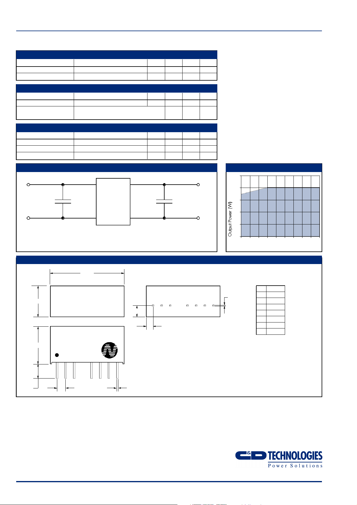
NDL05 POWER DERATING CURVE
2.5
2.0
1.75
1.5
1.0
0.5
5V & 12V: C
24V & 48V: C
100µF, 25V Philips Part No.13556101
IN
10µF, 200V Philips Part No.15162109
IN
MECHANICAL DIMENSIONS
21.80
9.20
NDL4805S
4.60
3.60
11.10
1 2 3 5 6 7 8
XYYWW
2.54
0.55
0.45
0
4.5 5 6 7 8 9
0.30 max
0.20 min
3.20
2.01±0.50
*Pin 5 is internally connected and must have no external connection
All dimensions in mm XX.XX ±0.25mm. All pins on a 2.54mm pitch and
within ±0.25mm of true position.
Input Voltage (V)
PIN
1 GND
2 V
IN
3 CTRL
5* IC
6 +V
OUT
7 0V
8 C
S
Weight: 5.0g
C&D Technologies (NCL) Limited reserve the right to alter or improve the
specification, internal design or manufacturing process at any time, without
notice. Please check with your supplier or visit our web site to ensure that
you have the current and complete specification for your product before use.
© C&D Technologies (NCL) Limited 2002 NDC NDL.4
No part of this publication may be copied, transmitted or stored in a
retrieval system or reproduced in any way including, but not limited to,
photography, photocopy, magnetic or other recording means, without prior
written permission from C&D Technologies (NCL) Limited.
Instructions for use are available from www.dc-dc.com
C&D Technologies (NCL) Ltd
Tanners Drive, Blakelands North
Milton Keynes MK14 5BU, England
Tel: +44 (0)1908 615232
Fax:+44 (0)1908 617545
email: info@cdtechno-ncl.com
www: http://www.dc-dc.com
C&D Technologies (NCL), Inc.
3400 E Britannia Drive, Tucson,
Arizona 85706, USA
Tel: +1 (800) 547-2537
Fax: +1 (520) 741-4598
email: sales@cdtechno.com
 Loading...