

Page 1

1. FEATURES
MX93521
APPLICATION NOTE V7
• Excellent sound quality by adopting 4.8Kbps CELP and
13Kbps speech compression alogorithm.
• Silent Compression algorithm to further compress si
lence between speech.
• Flash Memory Management alogorithm to manage
down-graded Flash Memory to store compressed
speech data. With silent compression, one 4Mbit flash
memory could store up to 18 minutes speech.
• Support 4/16/32/64M bit Samsung flash memory or
its compatible parts.
• Support both parallel and serial microprocessor interface.
• Codec Interface circuit (support both TP3054, MX93000
and MX93000C).
• Host controllable LCD Module Interface.
• Host writable message header (4 bytes) for identification or index purpose.
• Powerful Editing Function.
• Varieties of operating function including Rewind, Fast
Forward, Repeat and message editing etc.
• Voice activated recording.
• Use Flash memory to store user data (data bank)
• Upload/Download speech message data from/to
HOST.
• VOCODER mode (VOice COmpressor/
DEcompressoR).
• Direct CODEC Play Mode (Play PCM/u-Law data re
ceived from HOST).
• Play Voice Prompt from ROM/FLASH memory
• DTMF tone genarator.
2.GENERAL DESCRIPTION
This document describes how to implement an all-digital voice recorder using the MX93521 chip. The MX93521 is a
Digital Recorder Data Pump which is controlled by an external microprocessor to perform various recorder function.
The MX93521 is fully controlled by a HOST controller through a simple HOST interface protocol. The HOST could
initiate many digital recording functions such as record, play, repeat, search, skip, insertion, message managing and
self-diagnosis. Also, HOST could set MX93521 in VOCODER mode and use MX93521 as a speech compression/
decompression data pump. The functions supported by MX93521 are listed as followed.
MODE FUNCTION P A TH
RECORD CODEC-->(COMPRESS)-->FLASH
PLAY CODEC-->(DECOMPRESS)<--FLASH
RECORD (VOCODER) CODEC-->(COMPRESS)-->HOST
PLA Y (VOCODER) CODEC-->(DECOMPRESS)<--HOST
DIRECT CODEC PLA Y MODE CODEC-->(PCM/u-Law)<--HOST
DOWNLOAD MESSAGE FLASH(MSG)-->HOST
UPLOAD MESSAGE FLASH(MSG)<--HOST
DAT ABANK ACCESS FLASH(DAT A)<-- -->HOST
P/N:PM0688 REV. 3.3, APR 07, 2000
1
Page 2
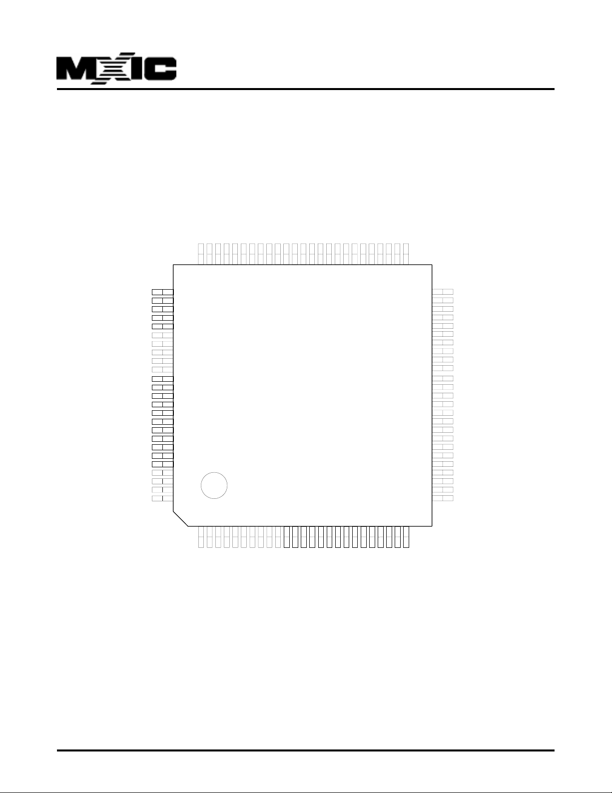
3.PIN CONFIGURATIONS
3.1 Pinout Assignments for MX93521 100-Pin LQFP (Parallel Mode)
100-LQFP PIN ASSIGNMENT
ED8
ED7
ED6
ED5
ED4
ED3
ED2
ED1
GND
VDSP
ED0
HOLD\
HOLDA\
EDCE\
EPCE\
ERD\
EWR\
EAD0
EAD1
75747372717069686766656463626160595857565554535251
ED9
ED10
ED11
ED12
ED13
VDSP
GND
ED14
ED15
XTLI
XTLO
NC
NC
NC
NC
MIC-E\
SPK-E\
RST\
EROM
SDEN\
SDATA
WP\
RxCmd
USO3
USO2
76
77
78
79
80
81
82
83
84
85
86
87
88
89
90
91
92
93
94
95
96
97
98
99
100
MX93521-V7
EAD2
EAD3
EAD4
EAD5
EAD6
FLL\
MX93521
50
49
48
47
46
45
44
43
42
41
40
39
38
37
36
35
34
33
32
31
30
29
28
27
26
EAD7
NC
EAD8
EAD9
EAD10
EAD11
EAD12
EAD13
EAD14
GND
VDSP
EAD15
VDSP
SCLK
VDSP
DSPDR
DA\
CMCLK
CFS
DSPDX
SOUT
PHDB0
PHDB1
PHDB2
PHDB3
P/N:PM0688
12345678910111213141516171819202122232425
NC
NC
LED2\
LED1\
CE1\
USO1
CE2\
ALE
USO0
CLE
X32I
X32O
P ACKB\
S/P
SIN
CODEC TYPE
R/B
NC
SHOLD\
GND
VDSP
PHDB7
PHDB6
PHDB5
2
PHDB4
REV. 3.3, APR 07, 2000
Page 3
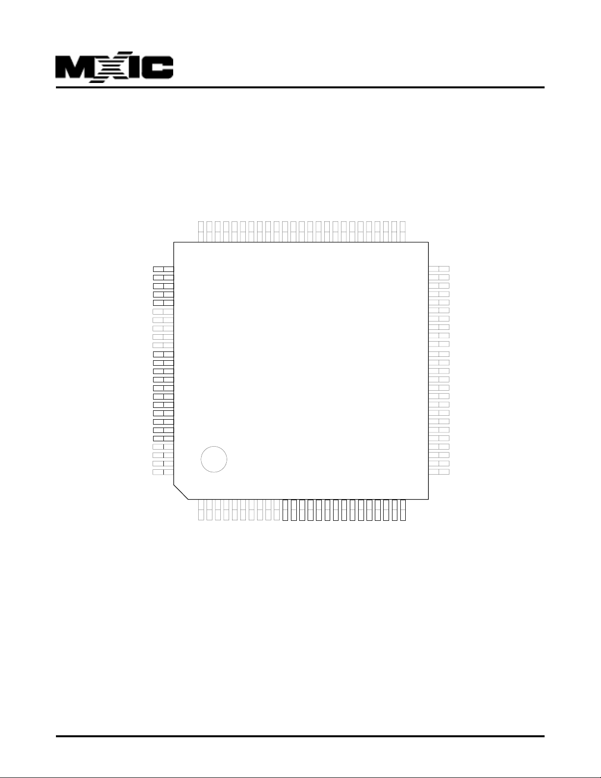
3.2 Pinout Assignments for MX93521 100-Pin LQFP (Serial Mode)
100-LQFP PIN ASSIGNMENT
ED8
ED7
ED6
ED5
ED4
ED3
ED2
ED1
GND
VDSP
ED0
HOLD\
HOLDA\
EDCE\
EPCE\
ERD\
EWR\
EAD0
75747372717069686766656463626160595857565554535251
ED9
ED10
ED11
ED12
ED13
VDSP
GND
ED14
ED15
XTLI
XTLO
NC
NC
NC
NC
MIC-E\
SPK-E\
RST\
EROM
SDEN\
SDATA
WP\
RxCmd
USO3
USO2
76
77
78
79
80
81
82
83
84
85
86
87
88
89
90
91
92
93
94
95
96
97
98
99
100
MX93521-V7
EAD1
EAD2
EAD3
EAD4
EAD5
EAD6
FLL\
MX93521
50
49
48
47
46
45
44
43
42
41
40
39
38
37
36
35
34
33
32
31
30
29
28
27
26
EAD7
NC
EAD8
EAD9
EAD10
EAD11
EAD12
EAD13
EAD14
GND
VDSP
EAD15
VDSP
SCLK
VDSP
DSPDR
DA\
CMCLK
CFS
DSPDX
SOUT
BIO0
BIO1
BIO2
BIO3
P/N:PM0688
12345678910111213141516171819202122232425
NC
NC
LED2\
LED1\
CE1\
USO1
CE2\
ALE
USO0
CLE
X32I
X32O
P ACKB\
S/P
SIN
CODEC TYPE
R/B
NC
SHOLD\
GND
VDSP
BIO7
BIO6
BIO5
3
BIO4
REV. 3.3, APR 07, 2000
Page 4

MX93521
4.PIN DESCRIPTION
4.1 DSP BASIC (22 PINS )
SYMBOL TYPE PIN # (LQFP) DESCRIPTION
VDSP 20,40,66,81,38,36 5V power source
GN D 21,41,67,82 Ground
FLL\ I 51 FLL\ low to set MX93521 running from single
low crystal
XTLI 8 5 32.256Mhz Crystal input
XTLO 86 32.256Mhz Crystal output
RST\ I 9 3 Power on Reset, Schmite triggered
PACKB\ OA 1 1 In serial mode, PACKB\ is N.C.
In parallel mode, PACKB\ becomes low when
MX93521 write data to BIO and high when
HOST read from BIO.
HOLD\ I 64 Hold DSP clock down and release bus
HOLDA\ OA 63 Ack to HOLD\ signal
EROM I 94 Disable internal ROM, use external ROM only
SCLK I 37 T ransmit/receive data clock
X32O OA 10 32.768Khz Crystal output
X32I 9 32.768Khz Crystal input
4.2 DSP EXTERNAL MEMORY(40 pins)
SYMBOL TYPE PIN # (LQFP) DESCRIPTION
EAD0-EAD15 OB 58~52,50,48~42,39 Address Bus
ED0~ED15 I/OB 65,68~80,83~84 Data Bus
EDCE\ OB 6 2 External data chip enable
EPCE\ OB 6 1 Resered for future use
ERD\ OB 60 Flash external read
EWR\ OB 59 Flash external write
N C 87~90 No connection
4.3 uP INTERF ACE(10 pins)
4.3.1 Serial Interface:(UPMODX=1)
SYMBOL TYPE PIN # (LQFP) DESCRIPTION
DA \ O C 34 Data Availab le (Output port OPT17)
SOUT O C 30 Serial Data Out (Output port OPT16)
BIO(7..0) OB 22~29 Drive LCD Display
P/N:PM0688
REV. 3.3, APR 07, 2000
4
Page 5
MX93521
4.3.2 Parallel Interface:(UPMODX=0)
SYMBOL TYPE PIN # (LQFP) DESCRIPTION
PHRDB\ I 34 Host read
PHWRB\ I 3 0 Host write
PHDB(7:0) B 22~29 Host data bus
4.4 CODEC (4 pins)
SYMBOL TYPE PIN # (LQFP) DESCRIPTION
CFS OB 32 Codec frame sync, 8Khz
CMCLK OB 33 Codec master clock, 1.536Mhz
DSPDX OA 3 1 Codec data transmit
DSPDR I 35 Codec data receive
4.5 OPT:OUT PORT(16 pins)
SYMBOL TYPE PIN # (LQFP) DESCRIPTION
CL E OC 8 Flash memory command latch enable
ALE OC 7 Flash memory address latch enable
N.C. 3,6
CE2\ OC 5 Chip enable 2
CE1\ OC 4 Chip enable 1
LED1\ OC 2 LED1 enable
LED2\ OC 1 LED2 enable
DR-V5
N.C.
RxCmd
WP\ OC 9 7 Flash memory write protection
SD AT A O C 96 Serial data transfer (for MX93000, MX93000C)
SDEN\ OC 95 Serial data enable (for MX93000, MX93000C)
SPK-E OC 92 Speaker enable,Hi-active
MIC-E\ O C 9 1 Microphone enable
USO3 OC 99 User output port
USO2 OC 100 User output port
USO1 OC 3 User output port
USO0 OC 6 User output port
DR-V5
OC 98 Received Command (toggle when re
ceived command from HOST)
P/N:PM0688
REV. 3.3, APR 07, 2000
5
Page 6
MX93521
4.6 IPT:INPUT PORT(8 pins)
SYMBOL TYPE PIN # (LQFP) DESCRIPTION
NC I 19
NC I 18
SHOLD\ I 17 Power down detect
NC I 16
R/B I 1 5 Flash memory Ready/Busy
CODECTYPE I 1 4 Codec select (TP3054B or MX93000, MX93000C)
SIN I 1 3 Serial data input
S/P\ I 12 Serial/paralled interface
NOTE:O A:2mA,OB:4mA,OC:16mA output current
P/N:PM0688
REV. 3.3, APR 07, 2000
6
Page 7
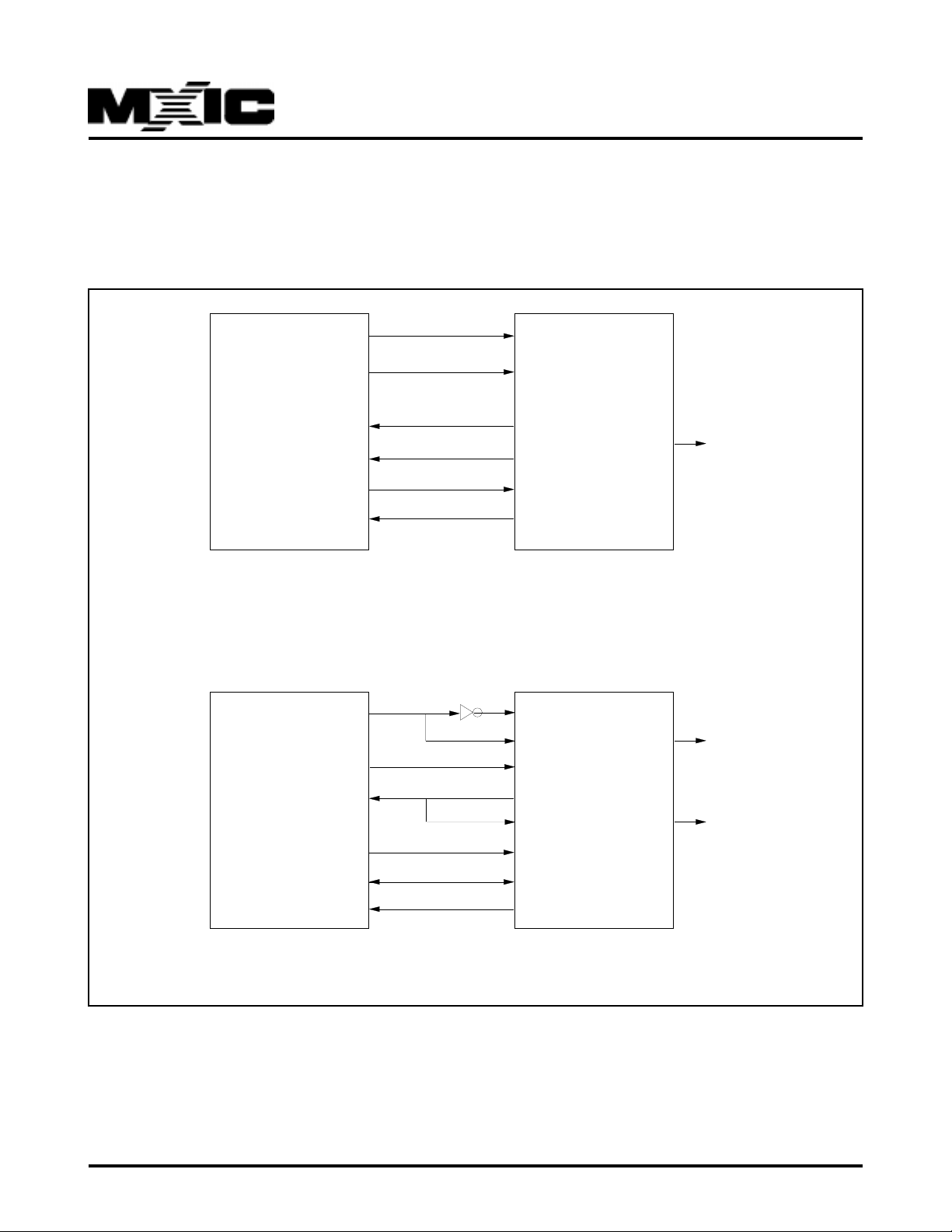
5. HOST CONTROLLER INTERFACE
5.1 HOST CONTROLLER INTERF ACE
5.1.1 Configuration
MX93521
HOST
HOST
OUT1
OUT2
IN1
IN2
OUT3
IN3
OUT1
OUT2
IN1
OUT3
D0-7
IN2
40
16
37
33
96
1
SERIAL MODE
40
33
37
14
16
96
32-25
1
SCLK
SIN
DA\
SOUT
RST\
RxCmd
SCLK
PHWRB\
PHRDB\
PACKB\
SIN
RST\
PHDB0-7
RxCmd
MX93521
PHILO\
MX93521
S/P\
S/P\
15
VCC
39
VCC
15
Gnd
P/N:PM0688
PARALLEL MODE
REV. 3.3, APR 07, 2000
7
Page 8
MX93521
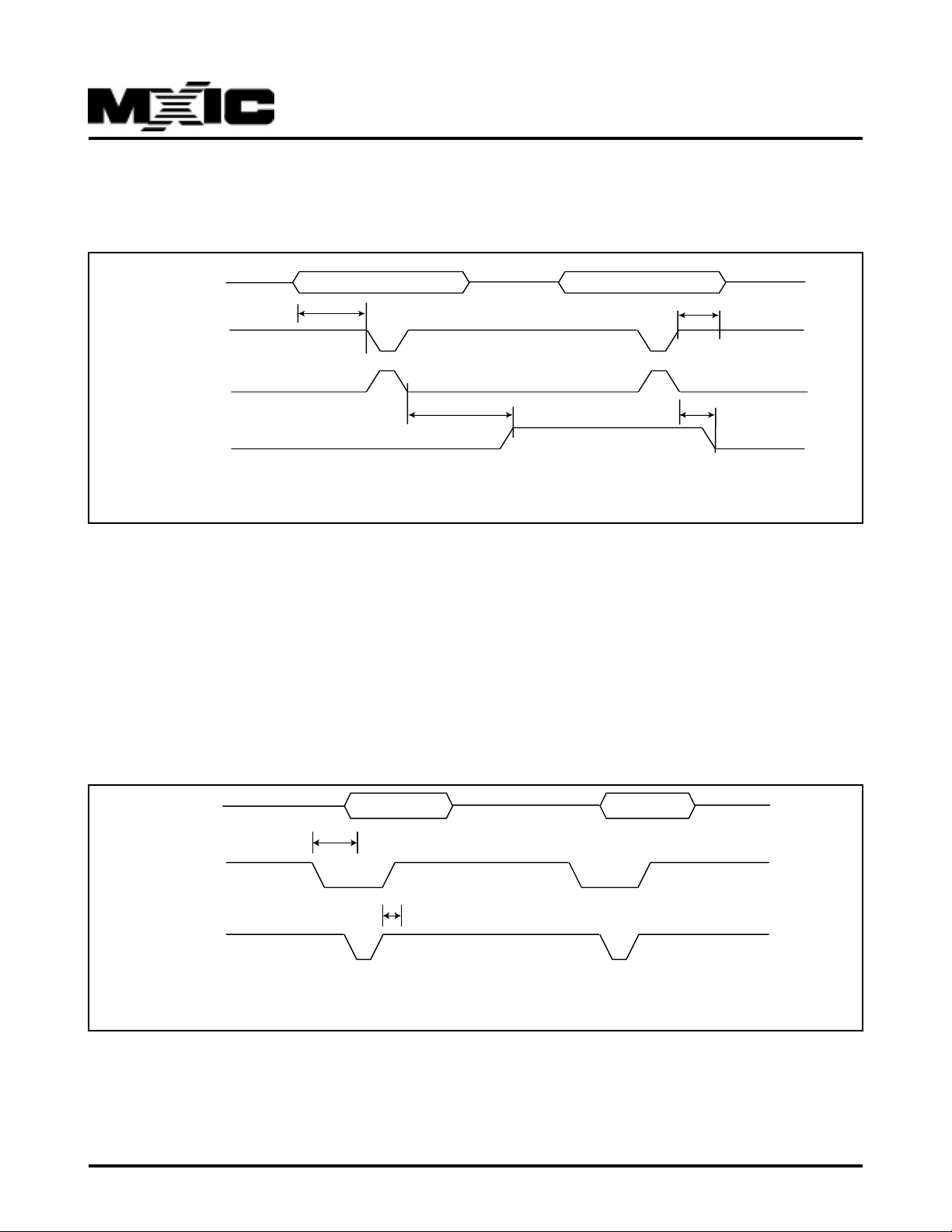
5.1.2 Timing Diagrams
HOST Write Timing (Parallel Mode)
PHDB0-7
ts
PHWRB\
SCLK
(INT1\)
RxCmd
HOST Write Timing (Parallel Mode)
tp
HOST should cycle PHWRB\ after writing data to PHDB0-7.
MX93521 will read data from PHDB0-7 on the falling edge of SCLK (rising edge of PHWRB\).
Rxcmd will be toggled if command byte has been processed by MX93521
th
tp
The PHWRB\ signal will cause MX93521 to latch data from bus PHDB0-7 to MX93521 internal register. The invertted
signal of PHWRB\ will trigger MX93521 INT1\ to read and process the received data byte from internal register. Due
to the interrupt contention, there might be an up to 50 us delay between the rising edge of PHWRB\ and INT1\ actually
being served. To keep from command overrun, HOST should check if RxCmd toggled or w ait 50 usec before sending
next command byte to MX93521.
HOST Read Timing (P arallel Mode)
PHDB0-7
ts
PACKB\
ta
PHRDB\
HOST Read Timing (Parallel Mode)
When MX93521 write data to PHDB0-7, P ACKB\ will become lo w. HOST needs to poll the status of PACKB\ continuously . When HOST detect low state on PACKB\, HOST should read out data from PHDB0-7. After HOST read the data
from PHDB0-7, PACKB\ will be reset to high.
The maxima delay between MX93521 write data to PHDB0-7 and PACKB\ become low is 10 ns.
The maxima delay between rising edge of PHRDB\ and PACKB\ become high is also 10 ns.
P/N:PM0688
REV. 3.3, APR 07, 2000
8
Page 9
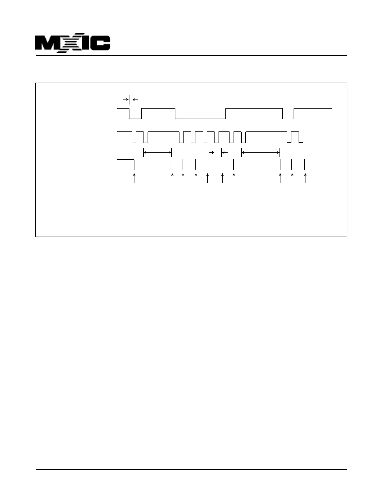
HOST Write Timing (Serial Mode)
HOST output data SIN
HOST output clock SCLK
MX93521
ts
tp
tp
tp
RxCmd
DSP Sampling from SIN
HOST send data 61H tp DSP
start d01d10d20d30d4
0
61H
d5
d61d70stop
1
HOST Write Timing (Serial Mode)
RxCmd become low when start bit is received from HOST and toggle state when MX93521 received each follo wing
data bit or stop bit from HOST . Thus, instead of waiting f or a fixed period of time (50us) to send a command bit, HOST
could send the following command bit as soon as RxCmd toggled from pre vious state. The dela y between the falling
edge of SCLK and the RxCmd togglling time is range from 1 us to 50 us
P/N:PM0688
REV. 3.3, APR 07, 2000
9
Page 10
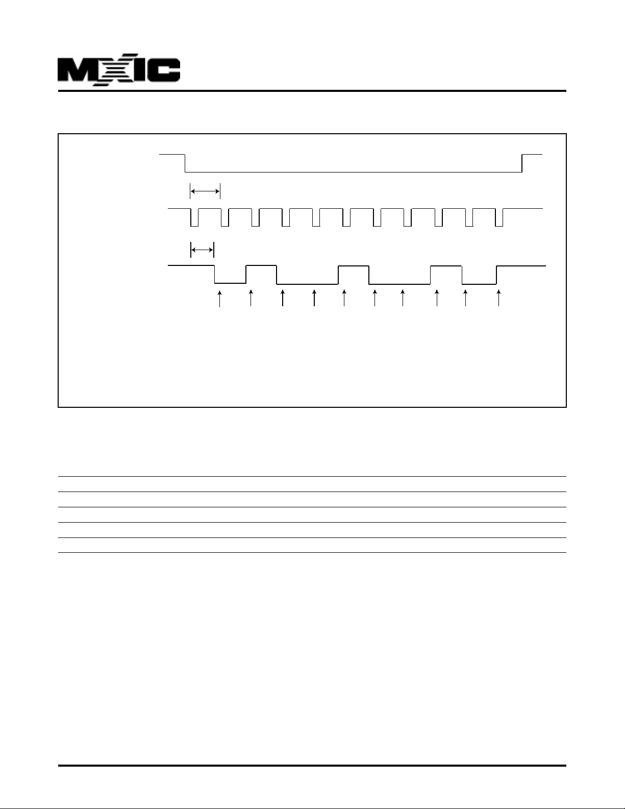
HOST Read Timing (Serial Mode)
DSP inform HOST
Data Available
DA\
>50us, clock rate
HOST output clock
SCLK
5-40us, SOUT response time
DSP output data
SOUT
HOST Sampling from
SOUT
DSP send data 49H
startx
to HOST
d0
d1
d2
1
0
d3
0
1
49H
HOST Read Timing (Serial Mode)
d4
MX93521
d5
0
0
d61d70stop
SOUT response time is 5-40us from the falling edge of SCLK
It is recommended that HOST sample SOUT right before the falling edge of SCLK
uP Interface Timing:
Min Max
Data setup time (ts) 10ns
Data hold time (th) 2ns
Data process time (tp) 1us 50us
P A CKB\ acknowledge time (ta) 5ns
P/N:PM0688
REV. 3.3, APR 07, 2000
10
Page 11

MX93521
5.2 MX93521 IO INTERF AC E
5.2.1 Output Port
PIN (PQFP) PIN (LQFP) P ower down state
LED1\ O 5 2 LED1 CONTROL High
LED2\ O 4 1 LED2 CONTROL High
USO3* O 2 99 User Programmable Output P ort High
USO2* O 3 100 User Programmable Output P ort High
USO1* O 6 3 User Programmable Output Port High
USO0* O 9 6 User Programmable Output Port High
* USO3, 2, 1, 0 are user output port and only available in DR-V7
5.2.2 Flash Memory Interface
MX93521 PIN Flash Power down state
NC I 22 X
NC I 21 X
NC I 19 X
CLE O 11 CLE Low
ALE O 10 ALE L ow
ERD\ O 63 R D\
CE2\ O 8 CE2\ High
CE1\ O 7 CE1\ High
EWR\ O 62 WR\
R\B I 1 8 R/B\
WP\ O 10 0 WP\ Low
ED0 IO 68 IO0
ED1 IO 71 IO1
ED2 IO 72 IO2
ED3 IO 73 IO3
ED4 IO 74 IO4
ED5 IO 75 IO5
ED6 IO 76 IO6
ED7 IO 77 IO7
5.2.3 CODEC Interface
MX93521 PIN Power down state
CODECTYPE I 17 (1: MX93000,MX93000C 0:TP3054)
DSPDR O 38
DSPDX O 34
CFS O 35
CMCLK O 36
SDA T A O 99 High
SDEN\ O 9 8 High
SPK_E O 95 Lo w
MIC_E\ O 94 High
P/N:PM0688
11
REV. 3.3, APR 07, 2000
Page 12
MX93521
5.2.4 uP Serial Mode Interface
MX93521 uP LC D
RxCmd O IN3 (optional) MX93521 Rxd Command Indicator
S/P\ I Vcc High, Serial Mode, Low=P arallel Mode
SCLK I OUT1 Serial Clock
DA \ O IN1 Data Available
SOUT O IN2 Serial Data Output
SHOLD\ I OUT3 DSP HOLD
SIN I OUT2 Serial Data Input
RST\ I OUT4 DSP RESET
BIO2 O E
BIO3 O RS
BIO4 O D4
BIO5 O D5
BIO6 O D6
BIO7 O D7
5.2.5 uP Parallel Mode Interface
MX93521 uP LCD
S/P\ I GN D Lo w , P ar allel Mode, High=Serial Mode
SCLK I OUT1\
PHRDB\ I OUT2 Read
PHWRB\ I OUT1 Write
SHOLD\ I OUT3 DSP HOLD
RST\ I OUT4 DSP RESET
PHILO\ I Vcc High, Byte Mode
SIN I IN 1 SIN should be connected to PACKB\ externally
PACKB\ O IN 1 Acknowledge
RxCmd O IN2 (optional) MX93521 Rxd Command Indicator
PHDB0 I/O D0
PHDB1 I/O D1
PHDB2 I/O D2
PHDB3 I/O D3
PHDB4 I/O D4
PHDB5 I/O D5
PHDB6 I/O D6
PHDB7 I/O D7
When SHOLD\ is low , MX93521 will go to power down mode .
When SHOLD\ change from low to high, DSP will power up and send ACK0 to HOST
P/N:PM0688
12
REV. 3.3, APR 07, 2000
Page 13

MX93521
6. HOST INTERFACE SOFTWARE COMMAND SET SUMMARY
6.1 HOST TO MX93521 COMMANDS
When MX9521 received a command from HOST, it will always respond the command with a ackno wledge. The
valid commands and corresponded ackno wledge are described as below .
D7 D6 D5 D4 D3 D2 D1 D0
0 0 0 0 1 B B B 008H POINT TO SPECIFIC MESSAGE
0 0 0 1 0 B B B 010H GET CURRENT MESSAGE INFOMATION
0 0 0 1 1 B B B 018H DELETE MESSAGE(S)
0 0 1 0 0 B B B 020H REC/PLA Y MISC . FUNCTION
0 0 1 0 1 B B B 028H RECORD MESSAGE
0 0 1 1 0 B B B 030H PLAY MESSAGE
0 0 1 1 1 B B B 038H SKIP FORW ARD/BACKW ARD PLA Y
0 1 0 0 0 B B B 040H MISC. FUNCTION
0 1 0 0 1 B B B 048H TONE GENERA T OR
0 1 0 1 1 B B B 058H MX93000 CODEC MISC. FUNCTION
0 1 1 0 0 B B B 060H LED DISPLAY
0 1 1 0 1 B B B 068H WRITE COMPRESSED V OICE D A TA T O MX93521
0 1 1 1 0 B B B 070H LCD COMMAND
0 1 1 1 1 B B B 078H LCD DAT A
1 0 0 0 0 B B B 080H OUTPUT COUNTER
1 0 0 0 1 B B B 088H Download/Upload Message
1 0 0 1 0 B B B 090H Set Silence level
DR-V4
1 0 0 1 1 B B B 098H Set ROM/RAM wait state
1 0 1 0 0 B B B 0A0H Read/Write RAM
1 0 1 0 1 B B B 0A8H Read ROM
DR-V4
DR-V5
1 0 1 1 x B B B 0BxH Data Bank Functions
1 1 0 0 x B B B 0CxH Data Bank Functions
1 1 0 1 0 B B B 0D0H Data Bank Functions
1 1 1 1 1 B B B 0F8H Play Voice Prompt
DR-V4
BBB:BYTES SEND FOLLOWING THIS COMMAND
DR-V5
DR-V5
DR-V4
DR-V4
DR-V4
MX93521 T O HOST ACKNO WLEDGES (OK Messages)
ACK0: 0A0H, NO D A TA ACCOMPNIED THIS ACKNO WLEDGE
ACK1: 0A1H, 1 DAT A A CCOMPNIED THIS A CKNOWLEDGE
ACK2: 0A2H, 2 DAT A A CCOMPNIED THIS A CKNOWLEDGE
ACK6: 0A6H, 6 DAT A A CCOMPNIED THIS A CKNOWLEDGE
MX93521 TO HOST A CKNOWLEDGES (ERROR Messgaes)
ERR0(0E0H): Command ERROR
ERR1(0E1H): Out of memory , MX93521 cannot perform RECORD function
ERR2(0E2H): No message found, MX93521 cannot perf orm PLA Y function
ERR3(0E3H): No Flash Memory Detected when power on
ERR4(0E4H): MX93521 Busy
ERR5(0E5H): Vocoder Mode , Play b uff er full, data rejected
ERR6(0E6H): No previous or next message found
ERR7(0E7H): MX93000 Command Busy
ERR8(0E8H): No empty block could be allocated for data bank usage
P/N:PM0688
13
DR-V4
REV. 3.3, APR 07, 2000
Page 14
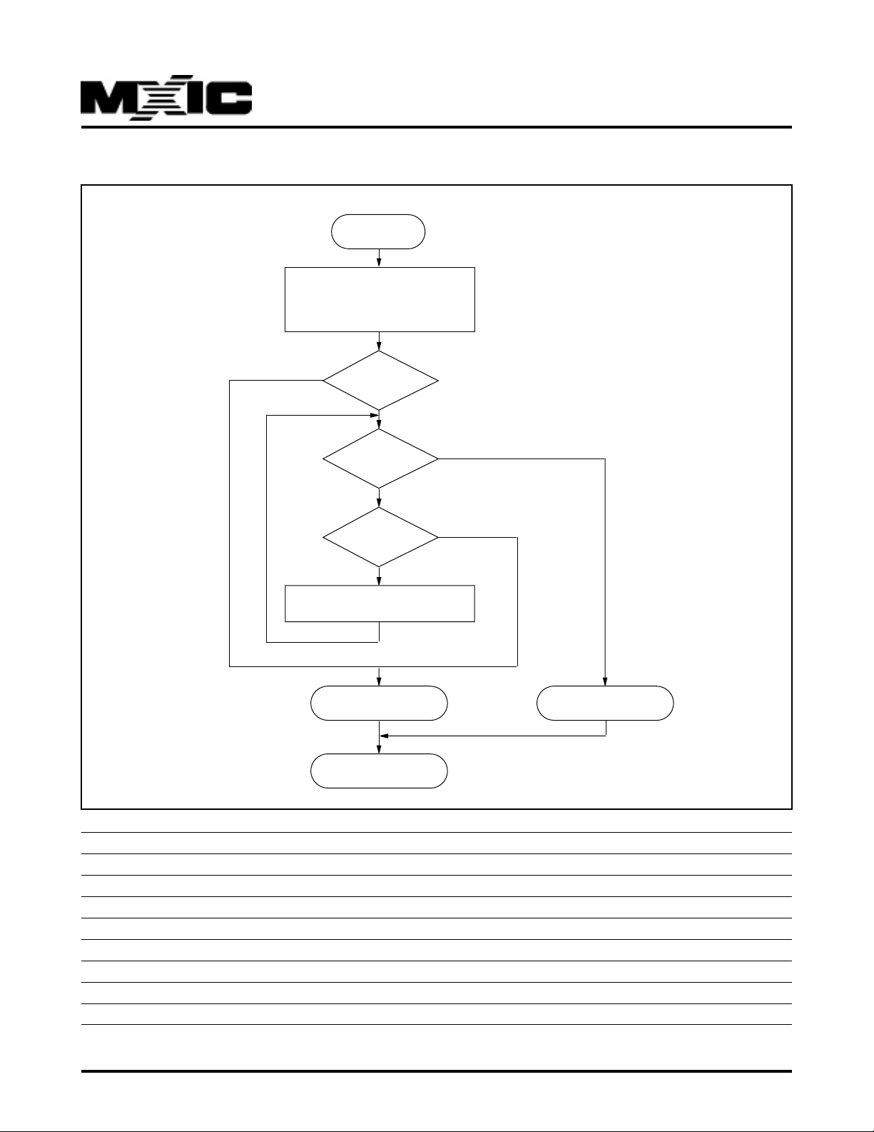
6.2 MX93521 Power On Initialization Flo w Chart
ST ART
Clear MX93521 internal RAM read
systemsetup serial or parallel?
TP3054 or MX93000, MX93000C?
Flash memory type and initial LCD
MX93521
NO
Flash memory
ID correct?
Is data link in
Flash memory correct?
NO
Is check data link
2nd time?
Format Flash memory &
create data link
Flash memory error
send CMD E3H
MX93521 Normal operation
YES
YES
NO
Flash memory OK send CMD
A1H+xxH
0A1H+000H RESERVED
0A1H+001H SANSUNG KM29N040, KM29W040, KM29N16000 AND KM29W16000 FLASH MEMORY
0A1H+002H SAMSUNG KM29W32000 FLASH MEMORY
0A1H+003H SAMSUNG KM29U64000 FLASH MEMORY
0A1H+004H RESERVED
0A1H+005H RESERVED
0A1H+006H RESERVED
0A1H+007H RESERVED
E3H NO FLASH MEMORY DETECTED
P/N:PM0688
14
REV. 3.3, APR 07, 2000
Page 15

MX93521
6.3 HOST TO MX93521 COMMAND DESCRIPTIONS
COMMAND 09H
FUNCTION: Move Message Pointer
RETURN: ACK0
RETURN: ERR6, IF REACH THE FIRST OR THE LAST MESSA GE IN THE MEMOR Y
DB7 DB6 DB5 DB4 DB3 DB2 DB1 DB0
00001001
DMMMMMMM
IF CURRENT MESSAGE NUMBER IS N,
D=0, JUMP FORW ARD D=1, JUMP BACKW ARD
M=001H, POINT T O THE MESSA GE (N+1) M=001H, POINT T O THE MESSA GE (N-1)
M=002H, POINT T O THE MESSA GE (N+2) M=002H, POINT T O THE MESSA GE (N-2)
M=07FH, POINT T O THE LAST MESSA GE M=07FH, POINT T O THE FIRST MESSAGE
COMMAND 0AH
FUNCTION: Point to specefic message
RETURN: ACK0
RETURN: ERR2, If no such message found in the FLASH memory
DB7 DB6 DB5 DB4 DB3 DB2 DB1 DB0
00001010
M M M M M M M M Message Number (High Byte)
M M M M M M M M Message Number (Low Byte)
*The message pointer is point to the last message in the flash memory upon power on.
SAMPLES:
Forward to the next message 09 H 01H
Rewind to the previous message 0 9 H 81H
Forward to the last message 09 H 7FH
Rewind to the the first message 0 9 H FFH
Move Message P ointer to message #258 (102H) 0AH 01 H 02 H
P/N:PM0688
REV. 3.3, APR 07, 2000
15
Page 16

MX93521
COMMAND 10H
FUNCTION: GET CURRENT MESSAGE INFOMA TION
RETURN: ACK6, DA TA1, DAT A2, D A TA3, DAT A4, D A TA5, DAT A6 or A CK0*
DB7 DB6 DB5 DB4 DB3 DB2 DB1 DB0
0001000 0
D ATA1: HIGH BYTE OF CURRENT MESSAGE NUMBER
D ATA2: LOW BYTE OF CURRENT MESSAGE NUMBER
DATA3: USER DAT A #1
DATA4: USER DAT A #2
DATA5: USER DAT A #3
DATA6: USER DAT A #4
*RETURN ACK0 WHEN NO MESSAGE IN THE MEMOR Y
SAMPLES:
GET CURRENT MESSAGE INFOMATION 10 H
COMMAND 11H
COMMAND 12H
COMMAND 13H
COMMAND 14H
FUNCTION: ATTACH USER DA T A TO CURRENT MESSAGE
RETURN: ACK0 or ERR0
DB7 DB6 DB5 DB4 DB3 DB2 DB1 DB0
00010BB B
USER DAT A #1
USER DAT A #2
USER DAT A #3
USER DAT A #4
* The USER D ATA is default to 0FFH
* Any data writen with this command will be AND with previous data
* When USER D ATA #1 is 055H. If write data 0AAH to it again, USER DATA #1 will become 0H
* If no message in the FLASH memory , MX93521 will return ERR0
SAMPLES:
A TTACH DATA 12H T O CURRENT MESSAGE 11 H 12H
A TTACH DAT A 12H/34H T O CURRENT MESSAGE 12 H 12 H 34H
A TTACH DAT A 12H/34H/56H T O CURRENT MESSAGE 13H 1 2H 34H 56H
A TTACH DAT A 12H/34H/56H/78H T O CURRENT MESSAGE 14 H 12H 34H 56 H 78 H
COMMAND 18H
FUNCTION: GET TOT AL MESSSAGE NUMBER
RETURN: ACK2, MSG_NO_HI, MSG_NO_LOW
DB7 DB6 DB5 DB4 DB3 DB2 DB1 DB0
00 0 1 1 0 0 0
P/N:PM0688
16
REV. 3.3, APR 07, 2000
Page 17
MX93521
COMMAND 19H
FUNCTION: DELETE MESSAGE(S)
RETURN: ACK0 after deletion completed
DB7 DB6 DB5 DB4 DB3 DB2 DB1 DB0
00 0 1 1 0 0 1
DM M M M M M M
IF CURRENT MESSAGE NUMBER IS N
D=0, DELETE FORW ARD
M=000H, DELETE CURRENT MESSAGE ONLY
M=001H, DELETE ONE MESSAGE AFTER MESSAGE #N (MSG #N WILL BE DELETED)
M=002H, DELETE TW O MESSA GES AFTER MESSA GE #N (MSG #N, #N+1 WILL BE DELETED)
M=07FH, DELETE ALL MESSAGES AFTER MESSA GE #N (MSG #N, #N+1,.., #LAST WILL BE DELETED)
D=1, DELETE BACKW ARD
M=001H, DELETE ONE MESSAGE BEFORE MESSAGE #N (MSG #N WILL BE DELETED)
M=002H, DELETE TW O MESSAGES BEFORE MESSA GE #N (MSG #N, #N-1 WILL BE DELETED)
M=07FH, DELETE ALL MESSAGES BEFORE MESSA GE #N (MSG #N, #N-1,.., #1 WILL BE DELETED)
SAMPLES:
DELETE CURRENT MESSAGE 19 H 0 0H
DELETE CURRENT MESSAGE 19 H 0 1H
DELETE CURRENT & NEXT MESSAGE 19 H 0 2 H
DELETE CURRENT & PREVIOUS MESSAGE 1 9 H 8 2H
DELETE ALL MESSAGES AFTER & INCLUDE CURRENT MESSAGE 19H 7FH
DELETE ALL MESSAGES BEFORE & INCLUDE CURRENT MESSAGE 1 9 H FFH
COMMAND 21H
FUNCTION: REC/PLAY MISC FUNCTION
RETURN:
DB7 DB6 DB5 DB4 DB3 DB2 DB1 DB0
00100001
MMMMMMMM
* THIS COMMAND ONL Y V ALID WHEN IN RECORD/PLA Y MODE
M Function Acknowledge Mode
01 H Stop Recording ACK2,CHKSUM_H,CHKSUM_L RE C
01 H Stop Playing ACK0 PLAY
02 H REC/PLA Y P A USE ON/OFF ACK0 REC/PLA Y
04 H T urn on counter display on LCD ACK0 REC/PLA Y
08 H Delete playing message ACK0 PLAY
10H Set REPEAT start point ACK0 PLAY
20 H Set REPEA T end point ACK0 PLAY
40 H Disable REPEA T mode ACK0 PLAY
80H Set Mark ACK0 REC/PLA Y
If HOST send command 21H/04H after REC or PLAY start, MX93521 will automatically display a 5-digit REC or
PLAY counter MM:SS at current LCD cursor. MM is minute. SS is second.
P/N:PM0688
REV. 3.3, APR 07, 2000
17
Page 18

MX93521
COMMAND 28H
COMMAND 29H
COMMAND 2AH
COMMAND 2BH
COMMAND 2CH
FUNCTION : RECORD MSG
BBB = 000, 001, 010, 011, 100
RETURN : ACK2, MSGNUM_H, MSGNUM_L
RETURN : A CK1, FORMA T (V OCODER mode, FORMAT=81H when recording with new format)
(VOCODER mode, FORMAT=80H when recording with old format)
RETURN: ERR1, WHEN OUT OF FLASH MEMORY, CANNO T PERFORM RECORD
DB7 DB6 DB5 DB4 DB3 DB2 DB1 DB0
00101BBB
USER DAT A #1
USER DAT A #2
USER DAT A #3
USER DAT A #4
* USER DATA will be stored in the flash memory
* When RECORD , MX93521 will not switch MIC on automatically, HOST must turn on MIC before RECORD and turn
off MIC after RECORD STOP
SAMPLES:
RECORD MESSAGE WITHOUT USER D A TA 28 H
RECORD MESSAGE WITH 1 USER DAT A 12H 29 H 12 H
RECORD MESSAGE WITH 2 USER D AT A 12H, 34H 2A H 1 2H 3 4H
RECORD MESSAGE WITH 3 USER D AT A 12H, 34H, 56H 2 BH 12H 3 4H 56 H
RECORD MESSAGE WITH 4 USER DAT A 12H, 34H, 56H, 78H 2CH 12H 34H 56 H 78 H
COMMAND 30H
COMMAND 31H
FUNCTION: PLA Y MESSAGE
RETURN: ACK2, MSGNUM_H, MSGNUM_L, ACK0(Vocoder mode)
RETURN: ERR2, No Message to play
DB7 DB6 DB5 DB4 DB3 DB2 DB1 DB0
00110001
M M M M M M M M LENGTH (sec / unit)
M=000H, PLA Y TILL THE END OF MESSAGE
M=001H, PLA Y CURRENT MESSA GE FOR 1 SEC
M=080H, PLA Y CURRENT MESSA GE FOR 128 SEC OR REACH THE END OF MESSAGE
M=0FFH, PLA Y CURRENT MESSA GE FOR 255 SEC OR REA CH THE END OF MESSA GE
* When PLAY , MX93521 will not s witch SPKR on automatically, HOST must turn on SPKR before PLA Y and turn off
SPKR after PLAY STOP
SAMPLES:
PLAY MESSAGE TILL THE END OF MESSAGE 30H
PLAY MESSAGE TILL THE END OF MESSAGE 31H 00H
PLA Y FIRST 3 SEC OF CURRENT MESSAGE 3 1H 03H
P/N:PM0688
18
REV. 3.3, APR 07, 2000
Page 19

COMMAND 39H
FUNCTION: JUMP TO MARK
RETURN: ACK0
DB7 DB6 DB5 DB4 DB3 DB2 DB1 DB0
001 11001
DMM MMMMM
D=0, FORW ARD D=1, BACKWARD
M=00H, Normal Playing
M=01H, Forward/Rewind to the 1st found mark from current position
M=02H, Forward/Rewind to the 2nd found mark from current position
..
M=7FH, Forward/Backward to the 127th found mark from current position
MX93521
mark#1
-
-
Pos#A
mark#2-mark#3
-
-
Pos#B
mark#4
-
If current playing position is at Pos#A, command 39H/01H will forward to mark#1
command 39H/02H will forward to mark#2
command 39H/03H will forward to mark#3
command 39H/04H will forward to mark#4
command 39H/05H will forward to the end of message
command 39H/81H will rewind to the head of message
If current playing position is at Pos#B, command 39H/01H will forward to mark#3
command 39H/02H will forward to mark#4
command 39H/03H will forward to the end of message
command 39H/81H will rewind to mark#2
command 39H/82H will rewind to mark#1
command 39H/83H will rewind to the head of message
* If two marks are set too close to each other(<2 second), the second mark will be ignored.
P/N:PM0688
19
REV. 3.3, APR 07, 2000
Page 20

MX93521
COMMAND 3AH
FUNCTION: FAST FORW ARD/BACKW ARD PLA YING
RETURN: ACK0
DB7 DB6 DB5 DB4 DB3 DB2 DB1 DB0
001110 10
DMMMMM MM
U U U U U U U U Unit Length (20ms/unit)
D=0, FORW ARD
M=00H, PLAY 1 UNIT, SKIP 0 UNIT (NORMAL PLAY SPEED)
M=01H, PLAY 1 UNIT, SKIP 1 UNIT (2x SPEED)
M=02H, PLAY 1 UNIT, SKIP 2 UNIT (3x SPEED)
M=03H, PLAY 1 UNIT, SKIP 3 UNIT (4x SPEED)
M=07H, PLAY 1 UNIT, SKIP 7 UNIT (8x SPEED)
..
M=7FH, PLAY 1 UNIT, SKIP 127 UNIT (128x SPEED)
D=1, BACKW ARD
M=01H, PLA Y 1 UNIT, REWIND 1 UNIT (REPEAT SAME UNIT)
M=02H, PLA Y 1 UNIT, REWIND 2 UNIT (1x SPEED REWIND)
M=03H, PLA Y 1 UNIT, REWIND 3 UNIT (2x SPEED REWIND)
M=05H, PLA Y 1 UNIT, REWIND 5 UNIT (4x SPEED REWIND)
..
M=7FH, PLA Y 1 UNIT, REWIND 127 UNIT (126x SPEED)
SAMPLES:
NORMAL PLA YING 39 H 00 H
FORW ARD T O THE 1ST FOUND MARK 3 9 H 01H
REWIND T O THE 2ND FOUND MARK 39H 82H
NORMAL PLA YING 3AH 00H 01H
PLAY 20ms and SKIP 20ms (2x speed) 3A H 01H 01H
PLA Y 20ms and REWIND 60ms (2x speed) 3A H 83 H 01 H
PLAY 40ms and SKIP 40ms 3AH 01H 02H
PLAY 100ms and SKIP 200ms 3AH 02 H 05H
PLA Y 100ms and REWIND 200ms 3A H 82 H 05H
P/N:PM0688
REV. 3.3, APR 07, 2000
20
Page 21

MX93521
COMMAND 41H
FUNCTION: MISC FUNCTION
RETURN:
DB7 DB6 DB5 DB4 DB3 DB2 DB1 DB0
010000 01
MMMMMM MM
M Function ACK OWLEDGE REMARK
01H T oggle VOCODER mode ACK0
02 H Append Recording ACK0 supported only in "4.8k" mode
03 H Overwrite Recording ACK0
04 H T oggle SPKR on/off ACK0 valid only when using TP3054
05 H Voice Activ ated Recording ACK0
06 H Linear mode codec interface ACK0
07 H u-law mode codec interface ACK0
08 H T oggle MIC on/off ACK0 valid only when using TP3054
09 H Play accross message boundary ACK0
0AH Play within message boundary ACK0
0BH4Direct CODEC Access ACK0
0CH5Old data format ACK0
0DH5New data format ACK0
10H1Erase all message ACK0 ack after erase complete
11H2Hard erase flash memory ACK0 ack after erase complete
12 H Reinitial flash memory ACK0 ack after erase complete
20H Check busy/Idle status ACK0 / ERR4
30 H T urn on 13kbps coding ACK0 / ERR4 change to 13kbps coding
31 H T urn off 13kbps coding ACK0 / ERR4 change to 4.8kbps coding
40 H Check available block ACK2,BLKCNT_H, BLKCNT_L
41H Check total block ACK2,BLKCNT_H, BLKCNT_L
42 H Check available time ACK3,MINH,MINL, SEC
43H Check total time ACK3,MINH, MINL, SEC
44 H Check message length ACK3,MINH, MINL, SEC
80H3Overrun counter ACK2,CNT_H,CNT_L VOCODER mode
81H3Get Message Checksum ACK2,CS_H,CS_L VOCODER mode
1
The command 41H/10H er ase all data in good blocks. After b lock erase, the flash management data will be written
back to the flash memory . If HOST use flash memory as speech data memory and data bank memory . The command
41H/10H will erase both of the memory. To erase only speech memory, use command 19H. To erase data bank
memory , use command 0CAH. The commands to control data bank memory are described from command 0B0H to
command 0D6H
2
Prior Samsung ship their flash memory to customer, they will test the parts and randomly write data 00H to those
bad blocks. During the first power on, MX93521 will scan flash memory and create a good/bad table accordingly . After
that, MX93521 will search the good/bad table during power on initialization. Unless good/bad table is missing, MX93521
will not do flash memory initialization again.
P/N:PM0688
21
REV. 3.3, APR 07, 2000
Page 22

MX93521
We call command 41H/11H is hard erase flash memory . Because this command will erase all data in both good and
bad blocks. It is possible to erase the data in those bad blocks and turn the bad blocks into good block. In this case,
the original bad blocks could be unstable during normal operation. So, w e are not recommend to use this command
unless it is necessary.
After send command 41H/11H, HOST should issue a hardware reset by toggling RST\.
3
Command 41H/80H & 41H/81H are only valid after recording in V OCODER mode.
4
HOST could send PCM or u-law format data to CODEC directly. In this mode, MX93521 send PCM/u-Law data
received from HOST to CODEC (MX93000 or TP3054). MX93521 could store up to 512 samples data internally. If
inetrnal buffer is empty , MX93521 will disab le this mode automatically and send CMD 10H to HOST . At the beginning
of Direct CODEC Access mode, MX93512 will not send data to CODEC until MX93521 received 384 samples from
HOST .
5
Old data format is the data format used in MX93510 and MX93521 V3. Ne w data format is used in MX93521 V4 and
V5. Ne w format supports silence compression. It is alw ays set to use ne w data format in MX93521 V4. MX93521 V5
will reset to use new data format after power on, RECORD or PLA Y. So , if HOST want to RECORD or PLA Y message
using old data format, HOST needs to send command 41H/0CH every time before sending RECORD or PLAY
command to MX93521.
COMMAND 42H
FUNCTION: DETECT M FRAMES SILENCE ON THE PLA Y/RECORD MODE
RETURN: ACK0
DB7 DB6 DB5 DB4 DB3 DB2 DB1 DB0
00 1 0 00 1 0
H H H H H H H H Silence Frame number (Hi-byte)
L L L L L L L L F rame number (Lo-byte) , 20ms/unit
SAMPLES:
DETECT 500 ms SILENCE ON THE PLAY/RECORD MODE 42H 00H 19 H
* This setting will be clear after play end of this message.
* When detect the silence condition , mx93521 will response the data of 28H
COMMAND 48H
FUNCTION: Tone Off
RETURN: ACK0
DB7 DB6 DB5 DB4 DB3 DB2 DB1 DB0
0 1 0 0 1 0 0 0 T one Off
COMMAND 49H
FUNCTION: BEEP GENERA TOR
RETURN: ACK0
DB7 DB6 DB5 DB4 DB3 DB2 DB1 DB0
0 1 0 0 1 0 0 1 1000Hz T ONE (100ms on / 100ms off)
C C C C C G G G GAIN
CCCCC: BEEP COUNT , MAXIMUM 31 BEEPS
P/N:PM0688
REV. 3.3, APR 07, 2000
22
Page 23

MX93521
COMMAND 4BH
FUNCTION: TONE GENERA TOR
RETURN: ACK0
DB7 DB6 DB5 DB4 DB3 DB2 DB1 DB0
01001011 TONE
L L L L L G G G LENGTH (100ms/unit) & GAIN
F1 5 F14 F13 F12 F11 F10 F9 F8 TONE FREQ (HIGH BYTE)
F7 F6 F5 F4 F3 F2 F1 F0 TONE FREQ (LO W BYTE)
GGG: 000 GAIN= -18 dB, 10 0 GAIN= -42 dB
00 1 GAIN= -24 dB, 101 GAIN= -4 8 dB
01 0 GAIN= -30 dB, 110 GAIN= -5 6 dB
01 1 GAIN= -36 dB, 111 GAIN= -6 2 dB
COMMAND 4EH
COMMAND 4FH
FUNCTION: DUAL TONE GENERA TOR
RETURN: ACK0
DB7 DB6 DB5 DB4 DB3 DB2 DB1 DB0
01001110
F15 F14 F13 F12 F11 F10 F9 F8 TONE#1 FREQ (HIGH BYTE)
F7 F6 F5 F4 F3 F2 F1 F0 TONE#1 FREQ (LOW BYTE)
F15 F14 F13 F12 F11 F10 F9 F8 TONE#2 FREQ (HIGH BYTE)
F7 F6 F5 F4 F3 F2 F1 F0 TONE#2 FREQ (LOW BYTE)
G1 G1 G1 G1 G1 G1 G1 G1 Scale for TONE#1
G2 G2 G2 G2 G2 G2 G2 G2 Scale for TONE#2
DB7 DB6 DB5 DB4 DB3 DB2 DB1 DB0
01001111
F15 F14 F1 3 F12 F11 F10 F9 F8 TONE#1 FREQ (HIGH BYTE)
F7 F6 F5 F4 F3 F2 F1 F0 TONE#1 FREQ (LOW BYTE)
F15 F14 F1 3 F12 F11 F10 F9 F8 TONE#2 FREQ (HIGH BYTE)
F7 F6 F5 F4 F3 F2 F1 F0 TONE#2 FREQ (LOW BYTE)
G1 G 1 G1 G1 G1 G1 G1 G 1 Scale for TONE#1
G2 G 2 G2 G2 G2 G2 G2 G 2 Scale for TONE#2
L L L L L L L L Length (10ms/unit)
P/N:PM0688
23
REV. 3.3, APR 07, 2000
Page 24

MX93521
F = (FREQ/8000)*65536
TONE (#) FREQ (HZ) F (DECIMAL) F (HEX) F (HIGH) F (LOW)
C5 523.25 4286.464 10BEH 10H BEH
D5 587.33 4811.407 12CBH 12H CBH
E5 659.26 5400.658 1519H 1 5H 19H
F5 698.46 5721.784 165AH 16 H 5AH
G5 783.99 6422.446 1916H 19H 1 6H
A5 880.00 7208.960 1C29H 1CH 29H
B5 987.77 8091.812 1F9CH 1FH 9 CH
C6 1046.50 8572.928 217DH 21H 7D H
D6 1174.66 9622.815 2597H 25H 97H
E6 1328.51 10883.154 2A83H 2AH 83H
F6 1396.91 11443.487 2CB3H 2CH B3H
G6 1567.98 12844.892 322DH 32H 2DH
A6 1760.00 14417.920 3852H 38H 52H
B6 1975.53 16183.542 3F38H 3FH 38H
C7 2093.00 17145.856 42F AH 42H FAH
DTMF F1 (Hz) F1 (Dec) F1 (Hex) F2 (Hz) F2 (Dec) F2 (Hex)
1 1209 9904.1 26B0H 697 5709.8 164EH
2 1336 10944.5 2AC1H 697 5709.8 164EH
3 1477 12099.6 2F44H 697 5709.8 164EH
A 1633 13377.5 3442H 697 5709.8 164EH
4 1209 9904.1 26B0H 770 6307.8 18A4H
5 1336 10944.5 2AC1H 770 6307.8 18A4H
6 1477 12099.6 2F44H 770 6307.8 18A4H
B 1633 13377.5 3442H 770 6307.8 18A4H
7 1209 9904.1 26B0H 852 6979.6 1B44H
8 1336 10944.5 2AC1H 852 6979.6 1B44H
9 1477 12099.6 2F44H 852 6979.6 1B44H
C 1633 13377.5 3442H 852 6979.6 1B44H
* 1209 9904.1 26B0H 941 7708.7 1E1DH
0 1336 10944.5 2AC1H 941 7708.7 1E1DH
# 1477 12099.6 2F44H 941 7708.7 1E1DH
D 1633 13377.5 3442H 941 7708.7 1E1DH
*For command 49H, 4BH, 4EH and 4FH. HOST have to make sure SPKR is on when using this commands.
*User could use scale factor in command 4EH&4FH combined with CODEC gain setting to set the desirable DTMF
tone level
P/N:PM0688
REV. 3.3, APR 07, 2000
24
Page 25

MX93521
SAMPLES:
PLAY 2 BEEPS W/ -42DB GAIN 49H 14 H
PLA Y TONE #C5 (523HZ) W/ -36DB GAIN FOR 2 SECOND 4BH A3H 10H BEH
PLA Y TONE #E5 (659HZ) W/ -48DB GAIN FOR 1 SECOND 4BH 5 5H 1 5 H 19H
Play DTMF-1 (High tone is 6 dB higher than low tone) 4EH 26 H B 0H 1 6 H 4 EH FF H 7 FH
Play DTMF-0 (High tone is 6 dB lower than low tone) 100ms 4F H 2AH C1 H 1E H 1DH 3F H 7FH 0A H
STOP PLA YING DTMF T ONE 48H
COMMAND 51H
FUNCTION: WRITE OUTPUT PORT UO0-2
RETURN: ACK0
DB7 DB6 DB5 DB4 DB3 DB2 DB1 DB0
01 0 1 0 0 0 1
X X X X X UO2 UO1 UO0
*CMD 51H is only available in version DR-V3 and DR-V4
COMMAND 5AH
FUNCTION: MX93000, MX93000C CODEC MISC. FUNCTION
RETURN: ACK0 or ERR7
DB7 DB6 DB5 DB4 DB3 DB2 DB1 DB0
01011010
XXXXXA2A1A0
D7 D6 D5 D4 D3 D2 D1 D0
*Please reference to MX93000 data sheet for the definition of the MX93000, MX93000C registers
SAMPLES:
T urn on MX93000, MX93000C MIC path 5AH 0 0H 4 8H
T urn off MX93000, MX93000C MIC path 5AH 0 0H 01H
Set MIC to maxima gain 5A H 0 2H 0FH
Set MIC to minima gain 5A H 0 2H 00H
T urn on MX93000, MX93000C SPKR path 5AH 0 0H 0 3H
T urn off MX93000, MX93000C SPKR path 5AH 0 0H 01H
Set SPKR to maxima gain 5A H 0 3H 00H
Set SPKR to minima gain 5A H 0 3H 0FH
P/N:PM0688
REV. 3.3, APR 07, 2000
25
Page 26

MX93521
COMMAND 61H
FUNCTION: LED DISPLA Y FUNCTION
RETURN: ACK0
DB7 DB6 DB5 DB4 DB3 DB2 DB1 DB0
01100001
LED2 LED1 T T T T T T
LED1=1, LED1 ON (MX93521 PIN5 LOW)
LED2=1, LED2 ON (MX93521 PIN4 LOW)
TTTTTT=0, NO FLASH
TTTTTT¹0, FLASH TIMER (64ms/unit)
SAMPLES:
LED1 ST AY ON 61 H 40 H
LED2 ST AY ON 61 H 80 H
LED1 FLASH (512ms ON / 512ms OFF) 61 H 48 H
LED2 FLASH (1024ms ON / 1024ms OFF) 6 1 H 90H
LED1 & LED2 FLASH (128ms ON / 128ms OFF) 61 H C2 H
LED1 & LED2 OFF 61 H 00 H
P/N:PM0688
REV. 3.3, APR 07, 2000
26
Page 27

MX93521
COMMAND 6AH
COMMAND 6CH
COMMAND 6EH
FUNCTION: WRITE COMPRESSED VOICE D A TA TO MX93521 FOR PLA YING (V OCODER mode)
RETURN: ACK0 / ERR5
BBB = 010, 100, 110
DB7 DB6 DB5 DB4 DB3 DB2 DB1 DB0
0 1 1 0 1 B B B WRITE DA TA T O MX93521
BYTE#1
BYTE#2
BYTE#3
BYTE#4
BYTE#5
BYTE#6
MX93521 equipped a 64 words PLAY BUFFER, HOST should keep feeding compressed voice data to MX93521
when doing PLA Y function. Once PLAY BUFFER have no enough data to pla y, MX93521 will stop playing and send
command 10H to HOST. When the PLAY BUFFER is full, MX93521 will response ERR5. If this is the case, HOST
should re-send this command later. HOST must feed MX93521 at least 12 bytes data per 20 mini-second. When
HOST send command 30H, MX93521 will not start to play until received first 60 bytes data.
The procedure to do PLA Y function in VOCODER mode:
STEP1:Turn on VOCODER mode (send command 41H/01H)
STEP2:Turn on SPKR
STEP3:Set PLAY mode (Send command 30H)
STEP4:Send Compressed V oice data to MX93521 (Send command 6?H+BYTE+BYTE+..)
STEP5:If received ACK0, goto STEP4 to send next 6AH/6CH/6EH command
If received ERR5, wait 20-180 ms, then go back to STEP4 to re-send previous command
If HOST want to stop PLAY function or HOST reach the end of message, then goto STEP6
If received 10H, goto STEP7 (HOST did not send data to MX93521 fast enough)
STEP6: Wait until MX93521 pla y out data in PLA Y BUFFER (receiv eing command 10H from MX93521)
STEP7: Turn off SPKR
STEP8: T urn off VOCODER mode (send command 41H/01H).
P/N:PM0688
REV. 3.3, APR 07, 2000
27
Page 28

MX93521
COMMAND 70H
COMMAND 71H
COMMAND 72H
COMMAND 73H
COMMAND 74H
COMMAND 75H
COMMAND 76H
COMMAND 77H
FUNCTION: WRITE LCD DA TA
BBB = 000, 001, 010, 011, 100, 101, 110, 111
RETURN: ACK0
DB7 DB6 DB5 DB4 DB3 DB2 DB1 DB0
01110BBBLCD DATA
BYTE#1
BYTE#2
BYTE#3
BYTE#4
BYTE#5
BYTE#6
BYTE#7
* THIS COMMAND ONLY V ALID WHEN MX93521 SET T O SERIAL INTERF A CE MODE
SAMPLES:
DISPLA Y [ABCD] ON LCD LINE 1 74 H 41H 42H 43 H 44H
COMMAND 79H
FUNCTION: WRITE LCD COMMAND
RETURN: ACK0
DB7 DB6 DB5 DB4 DB3 DB2 DB1 DB0
01111001
C7 C6 C5 C4 C3 C2 C1 C0
* THIS COMMAND ONLY V ALID WHEN MX93521 SET T O SERIAL INTERF A CE MODE
P/N:PM0688
REV. 3.3, APR 07, 2000
28
Page 29

MX93521
LCD COMMAND SET:
C7 C6 C5 C4 C3 C2 C1 C0
0000000101H Clear Display
0000001X02H Cursor return Home
0000010004H Cursor-1, no shift
0000010105H Cursor-1, shift
0000011006H Cursor+1, no shift
0000011107H Cursor+1, shift
0000100008H Display off
000011000CH Display on, Cursor off, Blink off
000011010DH Display on, Cursor off, Blink on
000011100EH Display on, Cursor on, Blink off
000011110FH Display on, Cursor on, Blink on
000100XX10H Move Cursor left
000101XX14H Move Cursor right
000110XX18H Display shift left
000111XX1CH Display shift right
1XXXXXXX80H-FFH Set DD RAM address
1000000080H Set cursor to the start of 1st line
11000000C0H Set cursor to the start of 2nd line
SAMPLES:
CLEAR LCD DISPLA Y 79 H 01H
SET CURSOR T O THE START OF LINE 1 79 H 80 H
SET CURSOR T O THE START OF LINE 2 79 H C0 H
SET CURSOR T O THE LINE 2, 3RD COLUMN 79 H C2 H
MOVE CURSOR LEFT 79 H 10H
MOVE CURSOR RIGHT 79 H 14 H
EXAMPLE:
To Display [RECORD ] at line #1 & [MM:SS] at line #2
CLEAR LCD DISPLA Y & RETURN CURSOR T O HOME 79 H 0 1H
DISPLA Y [RECORD ] AT LCD LINE 1 76H 52 H 45H 43H 4F H 52H 44H
SET CURSOR T O THE LINE 2, 4TH COLUMN 79 H C3 H
TURN ON COUNTER DISPLA Y ON LCD 2 1 H 0 4H
P/N:PM0688
REV. 3.3, APR 07, 2000
29
Page 30

MX93521
COMMAND 80H
FUNCTION: Request for RECORD/PLA Y counter
RETURN: ACK2, MINUTE, SECOND
DB7 DB6 DB5 DB4 DB3 DB2 DB1 DB0
10000000
COMMAND 81H
FUNCTION: Request for continuously RECORD/PLA Y counter
RETURN: ACK0
DB7 DB6 DB5 DB4 DB3 DB2 DB1 DB0
10000001
T T T T T T T T 128 ms/unit
When MX93521 received command 81H, MX93521 will periodically send command 42H (Section 6.4) to HOST.
HOST could display the RECORD/PLAY counter on LCD accordingly. This function will be disabled by MX93521
when RECORD/PLA Y stop.
COMMAND 88H
FUNCTION: Download Message
RETURN: ACK1, FORMA T (VOCODER mode, FORMAT=81H if message is recorded with new format)
(VOCODER mode, FORMAT=80H if message is recorded with old format)
DB7 DB6 DB5 DB4 DB3 DB2 DB1 DB0
10001000
Once MX93521 received this command, MX93521 will start to send compressed voice data to HOST by using
command 32H or 36H. When reach the end of message, MX93521 will send out command 30H. We recommend
HOST do checksum calculation during downloading. After download completed, use command 41H/81H to get the
checksum from MX93521 and compare if the checksum is match. The Chec ksum is calculated by EXCLUSIVE OR
all speech data in word format.
COMMAND 89H
FUNCTION: Upload Message (Vocoder mode)
RETURN: ACK2, MSGNUM_H, MSGNUM_L(Upload start) / ACK2, Chec ksum_H, checksum_L(Upload End)
DB7 DB6 DB5 DB4 DB3 DB2 DB1 DB0
10001001
mmmmmmmm
m=00H,Upload Start m=01H, Upload End
COMMAND 8AH
FUNCTION: Upload Data
RETURN: ACK0
DB7 DB6 DB5 DB4 DB3 DB2 DB1 DB0
10001010
D D D D D D D D High Byte
D D D D D D D D Low Byte
P/N:PM0688
30
REV. 3.3, APR 07, 2000
Page 31

COMMAND 8CH
FUNCTION: Upload Data
RETURN: ACK0
DB7 DB6 DB5 DB4 DB3 DB2 DB1 DB0
100011 00
D D D D D D D D High Byte
D D D D D D D D Low Byte
D D D D D D D D High Byte
D D D D D D D D Low Byte
COMMAND 8EH
FUNCTION: Upload Data
RETURN: ACK0
DB7 DB6 DB5 DB4 DB3 DB2 DB1 DB0
100011 10
D D D D D D D D High Byte
D D D D D D D D Low Byte
D D D D D D D D High Byte
D D D D D D D D Low Byte
D D D D D D D D High Byte
D D D D D D D D Low Byte
MX93521
COMMAND 91H
FUNCTION: Set Silence Level
RETURN: ACK0
DB7 DB6 DB5 DB4 DB3 DB2 DB1 DB0
100100 01
x x x x L L L L Level
LLLL=0000 (Level 0) Set Highest silence threshold (Some of the speech will be treated as silence)
LLLL=0011 (Level 3) Default value
LLLL=1111 (Level 15) Set Lowest silence threshold (All signal are treated as speech, No silence compression at
all)
COMMAND 98H
FUNCTION: Read ROM/RAM wait state setting
RETURN: ACK2, WSTH,WSTL
DB7 DB6 DB5 DB4 DB3 DB2 DB1 DB0
100100 00
P/N:PM0688
31
REV. 3.3, APR 07, 2000
Page 32

COMMAND 99H
FUNCTION: Set ROM/RAM wait state
RETURN: ACK0
DB7 DB6 DB5 DB4 DB3 DB2 DB1 DB0
10010001
O O O O A A A A Wait State
OOOO: RAM Wait State AAAA: ROM Wait State
COMMAND A2H
FUNCTION: Read MX93521 RAM
RETURN: ACK2, DA TA_H, DAT A_L
DB7 DB6 DB5 DB4 DB3 DB2 DB1 DB0
11010010
Address (High)
Address (Low)
MX93521
COMMAND A4H
FUNCTION: Write MX93521 RAM
RETURN: ACK0
DB7 DB6 DB5 DB4 DB3 DB2 DB1 DB0
11010100
* Only for testing purpose, user should not change any data in the RAM area
COMMAND AAH
FUNCTION: Read MX93521 internal ROM
RETURN: ACK2, DA TA_H, DAT A_L
DB7 DB6 DB5 DB4 DB3 DB2 DB1 DB0
11010010
Address (High)
Address (Low)
Data (High)
Data (Low)
Address (High)
Address (Low)
P/N:PM0688
REV. 3.3, APR 07, 2000
32
Page 33

MX93521
COMMAND B0H
FUNCTION: Output all blocks number which are used as data bank block
RETURN: ACK0
DB7 DB6 DB5 DB4 DB3 DB2 DB1 DB0
10110000
MX93521 return block number by sending command 32H/34H/36H and ended with command 30H
32H, BLK_H, BLK_L
34H, BLK_H, BLK_L, BLK_H, BLK_L
36H, BLK_H, BLK_L, BLK_H, BLK_L, BLK_H, BLK_L
30H
COMMAND B1H
FUNCTION: Read Flash Memory
RETURN: ACK0
DB7 DB6 DB5 DB4 DB3 DB2 DB1 DB0
10 1 10 0 01
Counter (read 1-255 byte from flash memory)
COMMAND B2H
FUNCTION: Read Flash Memory
RETURN: ACK0
DB7 DB6 DB5 DB4 DB3 DB2 DB1 DB0
101 10010
CNT_H
CNT_L (read 1-65535 bytes from flash memory)
When continuously read flash memory , MX93521 will send data with command 3XH to HOST & ended with command
30H. The address pointer will point to the next byte of the last b yte read. HOST could send another continuous read
command 0B1H or 0B2H to read out following data from flash memory .
COMMAND B8H
FUNCTION: Request for data bank block
RETURN: ACK2, BLK_H, BLK_L
DB7 DB6 DB5 DB4 DB3 DB2 DB1 DB0
10111000
P/N:PM0688
REV. 3.3, APR 07, 2000
33
Page 34

COMMAND BAH
FUNCTION: Set read/write starting address
RETURN: ACK0
DB7 DB6 DB5 DB4 DB3 DB2 DB1 DB0
10 1 11 0 10
COMMAND BCH
FUNCTION: Set read/write starting address
RETURN: ACK0
DB7 DB6 DB5 DB4 DB3 DB2 DB1 DB0
10 1 11 1 00
MX93521
Address Pointer (High)
Address Pointer (Low)
Block Number (High)
Block Number (Low)
Address Pointer (High)
Address Pointer (Low)
COMMAND C1H
COMMAND C2H
COMMAND C3H
COMMAND C4H
COMMAND C5H
COMMAND C6H
COMMAND C7H
FUNCTION: Write data to flash memory(Data Bank)
RETURN: ACK0 or ERR0 (Block number or address pointer is not accepted)
DB7 DB6 DB5 DB4 DB3 DB2 DB1 DB0
11 0 00 B BB
data to write to flash memory
data to write to flash memory
data to write to flash memory
data to write to flash memory
data to write to flash memory
data to write to flash memory
data to write to flash memory
P/N:PM0688
REV. 3.3, APR 07, 2000
34
Page 35

COMMAND CAH
FUNCTION: Erase Block (Release data block)
RETURN: ACK0 or ERR0
DB7 DB6 DB5 DB4 DB3 DB2 DB1 DB0
11 0 01 0 10
Block (High)
Block (Low)
COMMAND C0H
FUNCTION: Read user output port status
RETURN: ACK1, user output port status ( 4bits )
DB7 DB6 DB5 DB4 DB3 DB2 DB1 DB0
11 0 10 0 00
COMMAND D1H
FUNCTION: Set user output port
RETURN: ACK0
DB7 DB6 DB5 DB4 DB3 DB2 DB1 DB0
1101000 1
X X X X US03 US02 US01 US00
MX93521
COMMAND D4H
FUNCTION: Read 1 word data from flash memory
RETURN: ACK2, DA TA_H, DAT A_L
DB7 DB6 DB5 DB4 DB3 DB2 DB1 DB0
11 0 10 1 00
COMMAND D5H
FUNCTION: Write 1 byte data to flash memory
RETURN: ACK0
DB7 DB6 DB5 DB4 DB3 DB2 DB1 DB0
11 0 10 1 01
Block (High)
Block (Low)
Address (High)
Address (Low)
Block (High)
Block (Low)
Address (High)
Address (Low)
Data
P/N:PM0688
REV. 3.3, APR 07, 2000
35
Page 36

COMMAND D6H
FUNCTION: Write 1 word (2 bytes) data to flash memory
RETURN: ACK0
DB7 DB6 DB5 DB4 DB3 DB2 DB1 DB0
11 0 10 1 01
COMMAND F AH
FUNCTION: Play Voice Prompt F rom R OM
RETURN: ACK0
DB7 DB6 DB5 DB4 DB3 DB2 DB1 DB0
11 1 11 0 01
MX93521
Block (High)
Block (Low)
Address (High)
Address (Low)
Data (High)
Data (Low)
V oice Prompt ROM Starting address High Byte
V oice Prompt ROM Starting address Low Byte
COMMAND FCH
FUNCTION: Play Voice Prompt from FLASH memory
RETURN: ACK0
DB7 DB6 DB5 DB4 DB3 DB2 DB1 DB0
11 1 11 0 01
Flash Memory Block # (High Byte)
Flash Memory Block # (Low Byte)
Flash Memory Pointer (High Byte)
Flash Memory Pointer (Low Byte)
Flash Memory Pointer range from 10H to 0FFEH
* When MX93521 received command 0FAH or 0FCH from HOST, MX93521 start to play voice prompt from ROM/
FLASH. After pla ying out all data, MX93521 will send command 10H to HOST . The voice prompt data are compressed
speech data which is ended with one 0000H or six 0FFFFH in the data stream.
P/N:PM0688
REV. 3.3, APR 07, 2000
36
Page 37

MX93521
6.4 MX93521 TO HOST COMMANDS
MX93521 will always respond a A CK if received a command from HOST. Besides that, MX93521 will send command
to notify HOST that a specific event has happened. HOST could do action according to the command received.
COMMAND 10H
FUNCTION: Play mode, Reach the end of the playing message
DB7 DB6 DB5 DB4 DB3 DB2 DB1 DB0
00 0 10 0 00
COMMAND 18H
FUNCTION: Play mode, Reach the start of the playing message
DB7 DB6 DB5 DB4 DB3 DB2 DB1 DB0
00 0 11 0 00
COMMAND 20H
FUNCTION: Record mode, out of flash memory
DB7 DB6 DB5 DB4 DB3 DB2 DB1 DB0
00 1 00 0 00
COMMAND 42H
FUNCTION: MX93521 outputs record / play counter
DB7 DB6 DB5 DB4 DB3 DB2 DB1 DB0
01 0 00 0 10
M M M M M M M M Minute
S S S S S S S S Second
COMMAND 52H
FUNCTION: MX93521 outputs Message Number
DB7 DB6 DB5 DB4 DB3 DB2 DB1 DB0
01 0 10 0 10
Message number (high byte)
Message number (low byte)
P/N:PM0688
REV. 3.3, APR 07, 2000
37
Page 38

MX93521
COMMAND 30H
COMMAND 31H
COMMAND 32H
COMMAND 33H
COMMAND 34H
COMMAND 35H
COMMAND 36H
COMMAND 37H
FUNCTION: MX93521 outputs data with command 3XH and ending the function with command 30H
COMMAND 32H
FUNCTION: Vocoder record mode, MX93521 outputs compressed v oice data (silence frame)
DB7 DB6 DB5 DB4 DB3 DB2 DB1 DB0
00 1 10 0 10
BYTE #1
BYTE #2
COMMAND 36H
FUNCTION: Vocoder record mode, MX93521 outputs compressed voice data (speech frame)
DB7 DB6 DB5 DB4 DB3 DB2 DB1 DB0
00 1 10 1 10
BYTE #1
BYTE #2
BYTE #3
BYTE #4
BYTE #5
BYTE #6
When in V OCODER mode, MX93521 use this command to send compressed voice data to HOST.
MX93521 equipped with 64 byte buff er internally. If buffer is full, data will be discarded.
P/N:PM0688
REV. 3.3, APR 07, 2000
38
Page 39

MX93521
7. DC Characteristics¡G TA=0 to 70°C , VCC=5V±10¢H
Storage temperature range¡G-55°C - 150°C
SYMBOL PARAMETER CONDITION MIN TYP MAX UNIT
VC C supply voltage 4.5 5.0 5.5 Volt
GND ground 0 Volt
TTL LEVEL INPUT(IT)
VIH Input high voltage 2.0 V
VIL Input low voltage 0.8 V
SCHMITT TRIGGER INPUT (IS)
VIH Input high voltage 0.7*VCC V
VIL Input low voltage 0.3*VCC V
8mA OUTPUT (OA)
V OH Onput high voltage IOH=-8mA 2.4
V OL Onput low voltage IOL=8mA 0.4 V
16mA OUTPUT (OB)
V OH Onput high voltage IOH=-16mA 2.4 V
V OL Onput low voltage IOL=16mA 0.4 V
SUPPL Y CERRENT
ICC NORMAL 45 70 mA
ICC HOLD MODE 10 mA
ICC POWER DOWN 3 6 mA
P/N:PM0688
REV. 3.3, APR 07, 2000
39
Page 40

8.AC TIMING AND CHARACTERISTICS:
RESET TIMING
MX93521
RST\
EAD15~EAD0
ED15~ED0
CONTROL
SIGNALS
OPT18~OPT0
BIO7~BIO0
T w(rst)
0001PC=0000
valid valid
(inactive)
0000
Note: Control Signals
HOLDA\EDCE\EPCE\ERD\EWR\
CAS\RAS\DRD\DWR\
SYMBOL P ARAMETER MIN NOM MAX UNIT
T w(rst) Reset low pulse width 2*46.5ns
OUTPUT PORT TIMING
AD15-AD0
EAD15-EAD0
OPT18~OPT0
BIO7~BIO0
XF\
PC=N, SXF/RXF
or OUT XX
PC=N+1 PC=N+2
Td(a-o)
OUTPUT PORTS AND EXTERNAL FLA G(XF\) TIMING
SYMBOL P ARAMETER MIN NOM MAX UNIT
Td(a-o) Address to output ports delay time 0 10 ns
P/N:PM0688
40
REV. 3.3, APR 07, 2000
Page 41

CODEC TRANSMIT AND RECEIVE TIMING
S
S
MX93521
CMCK
CFS
CDR0
CDX0
Td(ch-fs)
Tc
Td(ch-fs)
Th(dr)
Ts(dr)
N=1 N=2 N=3 N=4 SAMPLING 16 BIT
Td(ch-dx)
N=1 N=2 N=3 N=4 TRANSMIT 16 BIT
Tlpd
Thpd
SYMBOL PARAMETER MIN NOM MAX UNIT
Tc CMCK cycle time 650 ns
Tlpd CMCK low pulse duration 31 5 33 5 ns
Thpd CMCK high pulse duration 31 5 3 35 ns
Td(ch-fs) CMCK to CFS delay time 20 ns
Td(ch-dx) CMCK rising edge to Dx valid 10 ns
Ts(dr) DR set-up time before CMCK falling edge 10 ns
Th(dr) DR hold time before CMCK falling edge 10 ns
INTERRUPT TIMING
INT0\
INT1\
INT2\
AD15-AD0
fetch N+0 fetch N+1 fetch N+1 fetch N+1 fetch I
Tw
SYMBOL PARAMETER MIN NOM MAX UNIT
Tw INT\ low pulse duration 3Q * ns
NOTE:Q=15.5 ns
P/N:PM0688
41
REV. 3.3, APR 07, 2000
Page 42

SRAM/ROM READ TIMING
MX93521
EDCE\,EPCE\
EAD15-EAD0
ERD\
ED15-ED0
SRAM WRITE TIMING
EDCE\
EAD15-EAD0
TCS
TAA
TDR
DATA IN
TOH
EWR\
ED15-ED0
TAS
TDW
DATA OUT
TWR
TDH
SYMBOL P ARAMETER MIN NOM MAX UNIT
TCS Chip select access time 26.5+WxT ns
TAA Address access time 26.5+WxT ns
TD R Data read setup time 12 ns
T O H Data hold from end of read 0 ns
TAS Address setup time 0 5 ns
T D W Data to EWR\ low overlap 1 2 ns
TD H Data hold from end of write 0 ns
TW R Write recovery time 0 ns
*NOTE: T=31ns
W:Wait state number
P/N:PM0688
REV. 3.3, APR 07, 2000
42
Page 43

HOLD TIMING
MX93521
EAD15-EAD0
ED15-ED0
EPCE\
EDCE\
EWR\
ERD\
HOLD\
HOLDA\
N N+1 N+2 N+3 N+4
T en(ah-a)
Ts(a-h)
Td(hh-ha)
SYMBOL PARAMETER MIN NOM MAX UNIT
Ts(a-h) Address set-up time before HOLD\ low 5 3Q-10 ns
Td(hh-ha) HOLD\ high to HOLD A\ high 0 1Q 1Q+10 ns
T en(ah-a) Address driven after HOLDA\ high 1Q-10 1Q 2Q ns
*NOTE: Q=15.5n
H/W requirement
1. READ/WRITE pulse T of host to MX93521, should be no longer than 0.125ms
T
PHWRB/PHRDB/
READ/WRITE
T < 0.125ms
2. The SAMSUMG flash WP\ pin request timing...
4.5 V olt
VCC
WP\
While power on, reset MX93521 after the external power e xceed 4.5 V olt.
When external power drop below 4.5 V olt, host should stop all functions and set MX93521 into po wer down mode.
P/N:PM0688
REV. 3.3, APR 07, 2000
43
Page 44

9.PACKAGE INFORMATION
A
B
E
CD
IHG
F
1
25
26
50
51
75
76
100
N
M
J
K
L
P
O
100-PIN LQFP
ITEM MILLIMETERS INCHES
A 16.00 ± .05 .630 ± .002
B 14.00 ± .05 .551 ± .002
C 14.00 ± .05 .551 ± .002
D 16.00 ± .05 .630 ± .002
E 12.00 [REF] .472 [REF]
F .60 [REF] .024 [REF]
G .60 [REF] .024 [REF]
H .16 [Typ.] .006 [Typ.]
I .50 [Typ.] .020 [Typ.]
J 1.00 [Typ.] .039 [Typ.]
K 0.60 [Typ.] .024 [Typ.]
L .25 [Typ.] .010 [Typ.]
M .10 max. .004 max.
N 1.4 ± .05 .055
O .10 min. .004 min.
P 1.50 max. .059 max.
NOTE: Each lead centerline is located within
.25mm[.01 inch] of its true position [TP] at a
maximum material condition.
MX93521
P/N:PM0688
REV. 3.3, APR 07, 2000
44
Page 45

MX93521
10. Ordering Information
P AR T NO. P ACKAGE
MX93521FC PQFP
MX93521UC LQFP
MX 93 521 ? C
MXIC COMMERCIAL
COMPANY 0-70oC
PREFIX
PACKAGE TYPE
U: LQFP
F AMILY
PREFIX PRODUCT NUMBER
P/N:PM0688
REV. 3.3, APR 07, 2000
45
Page 46

Appendix 2. Sample Flow Chart for HOST to Implement uP Serial Interface
call SND_RCVD_CMD ( ) every 50 usec
BYTE: txdata, cmdout[0..7]
SEND_RCVD_CMD( )
YES
SCLK low?
DA\ low?
NO
NIBBLE; tbcnt, txcnt
BIT: data2snd, clk, obit
MX93521
txdata, cmdin[0..7]
tbcnt, rxcnt
set SCLK high
RETURN
YES
txcnt++
txdata=cmdout [txcnt]
tbcnt
obit=1
txdata.0==0?
data2snd=0
txcnt=0
NO
YES
clk=0
tbcnt==0?
data2snd==0?
txdata=cmdout[0]
tbcnt=10
obit=0
tbcnt==10?
tbcnt==1?
txdata.0==0?
obit=1
txdata>>=1
YES
YES
YES
NO
YES
clk=1
obit=SOUT
rbcnt==9?
NO
rbcnt==0?
YES
obit==0?
YES
rbcnt ++
YES
NO
rxdata>>=1
rxdata=(obit<<7)
decode_cmd( )
rxcent=0
data bit
YES
YES
obit==0?
NO
cmdin[rxcnt]=rxdata
rbcent=0
rxdata=0
rxcnt==
(cmdin[0] & 7)
NO
rxcnt==0?
(cmdin[0] & 0xf0)
==0xe0?
NO
rxcnt ++
YES
NO
stop bit
error
rxcnt=0
rxdata=0
rbcnt=0
P/N:PM0688
YES
To send command to MX93521:
Load command to cmdout[0:7]
then set data2snd=1
After sending out all commands,
dats2snd will be cleared to 0.
tbcnt--
obit==1?
NO
SIN lowSIN high
clk=1
NO
46
CLK==1?
YES
set SCLK low
RETURN
Received a complete Command from MX93521.
Precess command which is stored in cmdin[0:7]
REV. 3.3, APR 07, 2000
Page 47

MX93521
Appendix 3. Recommend commands sequence to implement a digital recorder
(star* means function is optional)
A3.1 Record Message (TP3054):
Functions HOST send MX93521 Acknowledge
* T urn on SPKR 41H/04H ACK0
* Beep 49H/0AH ACK0
* Turn off SPKR 41H/04H ACK0
T urn on MIC 41H/08H ACK0
* LED #1 flash 61H/48H ACK0
* Append Recording 41H/02H ACK0
* Overwrite Recording 41H/03H ACK0
* Turn on Voice Activ ated Mode 41H/05H ACK0
Start to Record 28 H ACK2,MSG#_H,MSG#_L
* Clear LCD 79H/01H ACK0
* Display [RECORD] on LCD 76H/52H/45H/43H/4FH/52H/44H ACK0
* Move cursor to line #2, col #3 79H/C3H ACK0
* T urn on message counter displa y on LCD 21H/04H ACK0
A3.2 Stop Recording (TP3054):
Functions HOST send MX93521 Acknowledge
Stop Recording 21H/01H ACK2,CHKSUM_H, CHKSUM_L
T urn off MIC 41H/08H ACK0
* LED #1 off 61H/00H ACK0
* T urn on SPKR 41H/04H ACK0
* Beep 49H/0AH ACK0
* Turn off SPKR 41H/04H ACK0
A3.3 Out of Memory , Received command 20H fr om MX93521 during Recording (TP3054):
Functions HOST send MX93521 Acknowledge
T urn off MIC 41H/08H ACK0
* LED #1 off 61H/00H ACK0
* T urn on SPKR 41H/04H ACK0
* Beep 49H/0AH ACK0
* Turn off SPKR 41H/04H ACK0
P/N:PM0688
REV. 3.3, APR 07, 2000
47
Page 48

MX93521
A3.4 Play Message (TP3054):
Functions HOST send MX93521 Acknowledge
Move message pointer to specific message 09H/xxH ACK0/ERR6
T urn on SPKR 41H/04H ACK0
* Beep 49H/0AH ACK0
* LED #2 flash 61H/88H ACK0
Start to Play 30H ACK2,MSG#_H,MSG#_L
* Send msg counter to HOST every 512 ms 81H/04H ACK0
* Clear LCD 79H/01H ACK0
* Display [PLAY] on LCD 74H/50H/4CH/41H/59H ACK0
* Move cursor to line #2, col #3 79H/C3H ACK0
* T urn on message counter displa y on LCD 21H/04H ACK0
A3.5 Function During Playing Message
Functions HOST send MX93521 Acknowledge
* F ast Forward Pla ying (2x) 3AH/01H/01H ACK0
* Rewind Playing (2x) 3AH/81H/01H ACK0
* Set REPEAT start point 21H/10H ACK0
* Set REPEAT end point 21H/20H ACK0
* Disable REPEAT mode 21H/40H ACK0
A3.6 Stop Playing Message (TP3054):
Functions HOST send MX93521 Acknowledge
Stop Playing 21H/01H ACK0
* LED #2 off 61H/00H ACK0
* Beep 49H/0AH ACK0
T urn off SPKR 41H/04H ACK0
A3.7 End of Message, Received command 10H from MX93521 during Playing (TP3054):
Functions HOST send MX93521 Acknowledge
* LED #2 off 61H/00H ACK0
* Beep 49H/0AH ACK0
T urn off SPKR 41H/04H ACK0
P/N:PM0688
REV. 3.3, APR 07, 2000
48
Page 49

A3.8 Message Search
Functions HOST send MX93521 Acknowledge
1 T urn on SPKR 41H/04H ACK0
2 Move message pointer to the 1st msg 09H/FFH ACK0/ERR6
3 Play current message for 3 second 31H/03H ACK0
4 10H
5 Move message pointer to the next message 09H/01H ACK0/ERR6
6 if received ACK0, goto Step #3
if received ERR6, goto Step #7
7 Turn off SPKR 41H/04H ACK0
A3.9 Message Found
Functions HOST send MX93521 Acknowledge
1 Stop playing 21H/01H ACK0
2 Play current message 30 H ACK0
3 Turn off SPKR 41H/04H ACK0
MX93521
P/N:PM0688
REV. 3.3, APR 07, 2000
49
Page 50

MX93521
A3.10 The procedure f or using flash memory as data bank memory
HOST SEND MX93521 RESPONSE
1 Request a empty block to be used 0B8H 0A2H, BLK_H, BLK_L
as data block
2 Set continuous read start address 0BCH, BLK_H, BLK_L, ADR_H, ADR_L 0A0H
3 Continuous Read 20 bytes 0B1H, 14H 0A0H
037H,D1,D2,D3,D4,D5,D6,D7
037H,D1,D2,D3,D4,D5,D6,D7
036H,D1,D2,D3,D4,D5,D6
030H
Continuous Read 298 bytes 0B2H, 01H,2AH 0A0H
037H,D1,D2,D3,D4,D5,D6,D7
037H,D1,D2,D3,D4,D5,D6,D7
......
034H,D1,D2,D3,D4
030H
4 Continuous Write 7 bytes 0C7H,D1,D2,D3,D4,D5,D6,D7 0A0H
Continuous Write 6 bytes 0C6H,D1,D2,D3,D4,D5,D6 0A0H
Continuous Write 5 bytes 0C5H,D1,D2,D3,D4,D5 0A0H
Continuous Write 4 bytes 0C4H,D1,D2,D3,D4 0A0H
Continuous Write 3 bytes 0C3H,D1,D2,D3 0A0H
Continuous Write 2 bytes 0C2H,D1,D2 0A0H
Continuous Write 1 bytes 0C1H,D1 0A0H
5 Erase Block CAH, BLK_H, BLK_L 0A0H
6 Read 1 word from flash memory 0D4H, BLK_H, BLK_L, ADR_H, ADR_L 0A2H, DATA1, DATA2
7 Write 1 byte to flash memory 0D5H, BLK_H, BLK_L, ADR_H, ADR_L, D1 0A0H
8 Write 2 bytes to flash memory 0D6H, BLK_H, BLK_L, ADR_H, ADR_L, D1, 0A0H
D2
Each block in flash memory is 4K byte. The first 16 b ytes are reserved f or MX93521 as data link data, HOST could
read but could not write data to it. So, the host usab le data are from address 10H-0FFFH.
P/N:PM0688
50
REV. 3.3, APR 07, 2000
Page 51

Appendix 4. Flow Chart of using MX93521 in V OCODER mode (Parallel Interface)
A4.1 Record mode (Background)
RECORD
RESET MX93521
[BIT]
WAIT4ACK=1
RCVD=DATA2SND=0
STOP1=STOP2=0
PAUSE1=PAUSE2=0
END_OF_REC=0
[BYTE]
TXCNT=RXCNT=0
WAIT4ACK==0?
YES
NO
MX93521
WAIT4ACK==0?
YES
[VOCODER MODE ON]
CMDOUT[0]=0x41
CMOUT[1]=0x01
DATA2SND=WAIT4ACK=1
WAIT4ACK==0?
YES
[MIC ON]
CMDOUT[0]=0x5A
CMDOUT[1]=0x00
CMDOUT[2]=0x48
DATA2SND=WAIT4ACK=1
Wait 10 msec for MX93000 to settle
WAIT4ACK==0?
YES
[SET MIC GAIN]
CMDOUT[0]=0x5A
CMDOUT[1]=0x02
CMDOUT[2]=0x04
DATA2SND=WAIT4ACK=1
NO
NO
NO
TOGGLE PAUSE?
NO
STOP RECORDING?
NO
END_OF_REC==1?
YES
[VOCODER MODE OFF]
CMDOUT[0]=0x41
CMDOUT[1]=0x01
DATA2SND=WAIT4ACK=1
WAIT4ACK==0?
YES
RETURN
YES
PAUSE1=WATI4ACK=1
YES
PAUSE1=WATI4ACK=1
NO
NO
P/N:PM0688
WAIT4ACK==0?
YES
[STAR T T O RECORD]
CMDOUT[0]=0x28
DA TA2SND=WAIT4ACK=1
NO
REV. 3.3, APR 07, 2000
51
Page 52

A4.2 Play mode (Background)
PLAY
RESET MX93521
[BIT]
WAIT4ACK=1
RCVD=DATA2SND=0
[BYTE]
TXCNT=RXCNT=0
WAIT4ACK==0?
NO
YES
YES
MX93521
RCVD==1?
NO
CMDIN[0]==0x10?
YES
[VOCODER MODE ON]
CMDOUT[0]=0x41
CMOUT[1]=0x01
DATA2SND=WAIT4ACK=1
WAIT4ACK==0?
YES
[SPEAKER ON]
CMDOUT[0]=0x5A
CMDOUT[1]=0x00
CMDOUT[2]=0x03
DATA2SND=WAIT4ACK=1
Wait 10 msec for MX93000 to settle
WAIT4ACK==0?
YES
[SET SPKR GAIN]
CMDOUT[0]=0x5A
CMDOUT[1]=0x03
CMDOUT[2]=0x05
DATA2SND=WAIT4ACK=1
NO
NO
YES
WAT4ACK==0?
YES
CMDIN[0]==0xA0?
YES
CMDIN[0]==0xA0?
(LOAD DATA FROM MEMORY TO BYTE[0..5])
(LOAD NO MORE THAN 6 BYTES AT A TIME)
(BYTECNT=BYTES LOADED)
CMDOUT[0]=0x68+BYTECNT
FOR (i=0; i<BYTECNT;i++)
NO
NO
CMDIN[0]==0xE5?
YES
[MX93521 BUSY]
[RESEND PREVIOUS DATA]
DELAY 2 msec
DATA2SND=WAIT4ACK=1
NO
P/N:PM0688
Wait 10 msec for MX93000 to settle
WAIT4ACK==0?
YES
[STAR T T O RECORD]
CMDOUT[0]=0x30
DA TA2SND=WAIT4ACK=1
NO
[VOCODER MODE OFF]
CMDOUT[0]=0x41
CMDOUT[1]=0x01
DATA2SND=WAIT4ACK=1
WAIT4ACK==0?
RETURN
52
NO
YES
REV. 3.3, APR 07, 2000
Page 53

A4.3 Command/Data Send/Receive Handling Routine (Interrupt)
INTERRUPT
MX93521
PACK\ = LOW?
YES
[READ DATA FROM MX93521]
RXDATA[7..0]=BIO[7..0]
STOP2==1?
NO
STOP1==1?
NO
CMDIN[RXCNT]=RXDATA
RXCNT==
CMDIN[0]& 0x7 ?
YES
DECODE_CMD ( )
RXCNT=0
NO
YES
YES
[WRITE CMD TO MX93521]
BIO=0x21
STOP2=1
NO
(RXCNT==0) &&
(CMDIN[0] &0xF0
==0xE0?
NO
RXCNT++
[WRITE CMD TO MX93521]
BIO=0x01
STOP1=STOP2=1
[WRITE DATA TO MX93521
DATA2SND==1?
YES
BIO=CMDOUT[TXCNT]
TXCNT==
CMDOUT[0] & 0x7 ?
YES
NO
NO
P/N:PM0688
53
TXCNT=0
DATA2SND=0
RETURN
TXCNT++
REV. 3.3, APR 07, 2000
Page 54

A4.4 Received Command Interpretation Routine (Interrupt)
DECODE_CMD ( )
MX93521
CMDIN[0]==0x36?
NO
CMDIN[0]==0x32?
NO
CMDIN[0]==0x30?
NO
CMDIN[0]==0x10?
YES
YES
[WRITE DATA TO MEMORY}
BYTECNT=CMDIN{0} & 0x7
FOR (i=0; i<BYTECNT; i++)
BYTE[i] =CMDIN[i+1]
YES
END_OF_REC=1
YES
RCVD=1
P/N:PM0688
CMDIN[0] & 0xF0
==0xA0?
NO
CMDIN[0] & 0xF0
==0xE0?
NO
RETURN
YES
YES
END_OF_REC=1
REV. 3.3, APR 07, 2000
54
Page 55

MX93521
MACRONIX INTERNATIONAL CO., LTD.
HEADQUARTERS:
TEL:+886-3-578-6688
FAX:+886-3-563-2888
EUROPE OFFICE:
TEL:+32-2-456-8020
FAX:+32-2-456-8021
JAPAN OFFICE:
TEL:+81-44-246-9100
FAX:+81-44-246-9105
SINGAPORE OFFICE:
TEL:+65-348-8385
FAX:+65-348-8096
TAIPEI OFFICE:
TEL:+886-2-2509-3300
FAX:+886-2-2509-2200
MACRONIX AMERICA, INC.
TEL:+1-408-453-8088
FAX:+1-408-453-8488
CHICAGO OFFICE:
TEL:+1-847-963-1900
FAX:+1-847-963-1909
http : //www.macronix.com
MACRONIX INTERNATIONAL CO., LTD. reserves the rignt to change product and specifications without notice.
55
 Loading...