

Page 1

1
P/N:PM0689 REV. 1.0.3,DEC. 13, 1999
MX93032
1.0 GENERAL DESCRIPTIONS
• MX93032-M1 is an engine chip on which digital answering machine (DAM) with full duple x speaker phone
is implemented. Besides, CAS tone detection capability and FSK decoder for Caller-ID service has also
been implemented as well.
• It provides speech processing / management modules, including speech compression/decompression,
silence management, telephone line signal processing, Macronix MX29F16A FLASH management, line
echo cancellation and acoustical echo cancellation,
etc.
• The MX93032-M1 has built-in DSP mode and MCU
mode. In DSP mode, users do not need external microprocessors and can effectively reduce the overall
system cost in DAM with full-duplex speakerphone
system. In MCU mode, the MX93032-M1 is controlled
by an MCU (micro controller) via a 8 bit parallel or
serial interface.
2.0 FEATURES
• Switchable 4.8kbps/12.8kbps speech compression/
decompression algorithm for message recording/playback.
• Minimum 15 or 40 minutes of recording time for one
16M bits MX29F16A FLASH based on 12.8K or 4.8K
compression rate, respectively.
• Low (4.8kbps) or High (12.8kbps) compression rate
with silence management technique for voice prompt
making. V oice prompt can be stored in Flash memory .
• Support total 127 messages, maximum 7 OGMs and
maximum 8 personal mailboxes.
• DTMF generation and detection with near-end echo
cancellation.
• Provide single low crystal solution (FLL).
• Built-in DSP mode and MCU mode. In DSP mode,
user can mask the system code into the MX93032M1. In MCU mode, user can control the MX93032-M1
via MCU (micro controller).
• Provide standard sample program written by 8051
assemble for customer development.
• Full duplex speakerphone with both acoustical echo
canceller (AEC) and line echo canceller (LEC)
• Built-in CAS signal detector for monitoring the presence CPE alerting signal in Calling Identity Delivery
on Call W aiting.
• FSK decoder for Calling Identity Delivery on CID T ype
I and CID Type II
• Caller ID Type II can be turned on under speaker phone
mode
• Auto detecting MCU mode and DSP mode
APPLICATION NOTE [M1 VERSION]
Page 2
2
P/N:PM0689
REV. 1.0.3, DEC. 13, 1999
MX93032
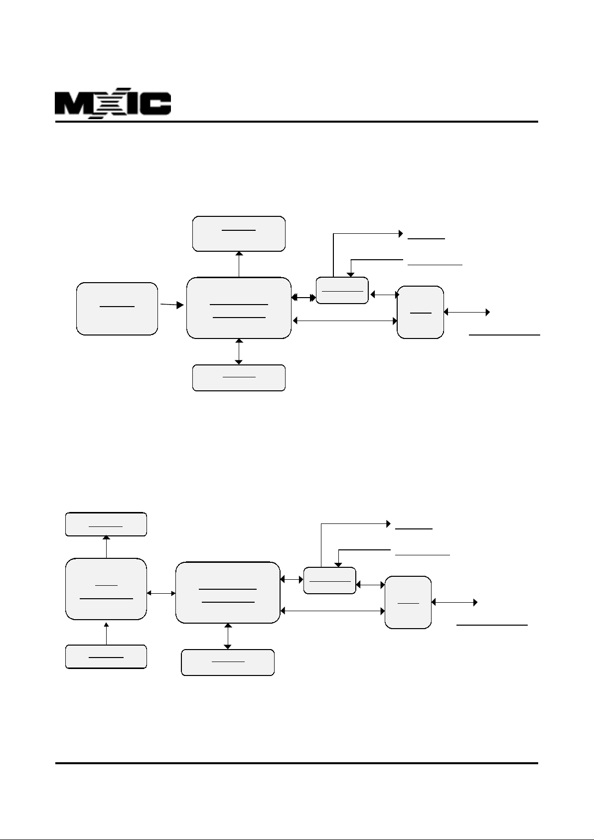
3.0 BLOCK DIAGRAM
DSP MODE
MCU MODE
Dis play
MX93032 -M1
Commands
FLASH
Keyp ad
MX93002
DAA
Spea ker
Microphone
Telephone Line
Display
MX93032-M1
Commands
FLASH
MCU
Commands
Keypad
MX93002
DA A
Speaker
Microphone
Telephone L ine
Page 3
3
P/N:PM0689
REV. 1.0.3, DEC. 13, 1999
MX93032
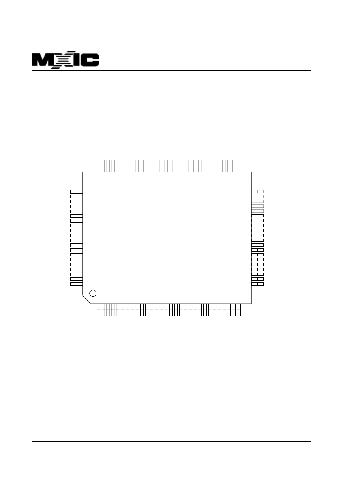
4.0 PIN CONFIGURATIONS
4.1 MCU MODE
EAD9
EAD10
EAD11
EAD12
EAD13
EAD14
GND
VDD
EAD15
NMI\
INT1\/SCKL
PHILO
CDR0
PHRD\
CMCK
CFS
CDX0
PHWR\
PHDB0
PHDB1
ED11
ED12
ED13
VDD
GND
ED14
ED15
X1\VDD
X2\GND
A19
A18
A17
IPT8
FCE2\
FCE1\
RST\
EROM
SDEN\
SDATA
A16
A15
OPT9
OPT8
OPT7
OPT6
OPT5
OPT4
OPT3
OPT2
OPT1
OPT0
X32I
X32O
PACK\
CDR1
PDN
IPT5
IPT4
IPT3
P/S
IPT1
IPT0
VDD
GND
SI/PHDB7
SO/PHDB6
PHDB5
PHDB4
PHDB3
PHDB2
ED10
ED9
ED8
ED7
ED6
ED5
ED4
ED3
ED2
ED1
GND
VDD
ED0
HOLD\
CDX1
EDCE\
EPCE\
ERD\
EWR\
EAD0
EAD1
EAD2
EAD3
EAD4
EAD5
EAD6
FLLEN\
GND
EAD7
EAD8
1234567891011121314151617181920212223242526272829
30
50
49
48
47
46
45
44
43
42
41
40
39
38
37
36
35
34
33
32
31
8079787776757473727170696867666564636261605958575655545352
51
81
82
83
84
85
86
87
88
89
90
91
92
93
94
95
96
97
98
99
100
MX93032-M1
Page 4
4
P/N:PM0689
REV. 1.0.3, DEC. 13, 1999
MX93032
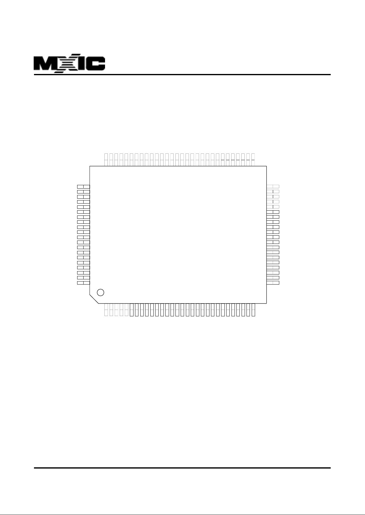
4.2 DSP MODE
EAD9
EAD10
EAD11
EAD12
EAD13
EAD14
GND
VDD
FAD15
NMI\
INT1\
A16
CDR0
A15
CMCK
CFS
CDX0
OPT16PHDB0
PHDB1
ED11
ED12
ED13
VDD
GND
ED14
ED15
X1\VDD
X2\GND
A19
A18
A17
IPT8
FCE2\
FCE1\
RST\
EROM
SDEN\
SDATA
OPT11
OPT10
OPT9
OPT8
OPT7
OPT6
OPT5
OPT4
OPT3
OPT2
OPT1
OPT0
X32I
X32O
XF\
CDR1
IPT6
IPT5
IPT4
IPT3
IPT2
IPT1
IPT0
VDD
GND
BIO7
BIO6
BIO5
BIO4
BIO3
BIO2
ED10
ED9
ED8
ED7
ED6
ED5
ED4
ED3
ED2
ED1
GND
VDD
ED0
HOLD\
CDX1
EDCE\
EPCE\
ERD\
EWR\
EAD0
EAD1
EAD2
EAD3
EAD4
EAD5
EAD6
FLLEN\
GND
EAD7
EAD8
1234567891011121314151617181920212223242526272829
30
50
49
48
47
46
45
44
43
42
41
40
39
38
37
36
35
34
33
32
31
8079787776757473727170696867666564636261605958575655545352
51
81
82
83
84
85
86
87
88
89
90
91
92
93
94
95
96
97
98
99
100
MX93032-M1
Page 5

5
P/N:PM0689
REV. 1.0.3, DEC. 13, 1999
MX93032
5.0 PIN DESCRIPTIONS
POWER/CLOCK/CONTR OL PINS :
SYMBOL PIN TYPE PIN NUMBER DESCRIPTION
VD D 23, 43, 69, 84 5V power source
GND 24, 44, 53, 70, 85 Ground
X1/VDD 88 32.256MHz crystal input/Connect to VDD in single low X'tal mode
X2/GND 8 9 32.256MHz crystal output/Connect to GND in single low X'tal mode
RST\ IS 96 Po wer-on reset
XF\ OA 14 External flag if UPMODX=1. This pin can be directly written by one
DSP instruction. Default inactive (5V output)
HOLD\ IS 67 Hold DSP clock down and release bus
EROM IS 97 Disable internal ROM, use external ROM only
NMI\ IS 41 Non-maskable interrupt pin
INT1\ IS 40 Interrupt pin
X32O 13 32.768KHz crystal output
X32I 12 32.768KHz crystal input
FLLEN\ IS 54 1 : Dual X'tal mode
0 : Single low X'tal mode
P/S IS 20 1:Parallel interf ace in MCU mode
0:Seriall interface in MCU mode
PDN IS 1 6 0:POWER DOWN
CODEC INTERF ACE PINS :
SYMBOL PIN TYPE PIN NUMBER DESCRIPTION
CFS OA 3 5 Codec frame sync, 8KHz (9.6KHz). Output low in power down mode.
CMCK OA 36 Codec master clock, 1.536MHz. Output low in power down mode.
CDX0 OA 3 4 Codec data transmit
CDR0 IS 38 Codec data receive
CDX1 OA 66 Codec data transmit
CDR1 IS 15 Codec data receive
SDEN\ OB 9 8 Serial data enable(for MXIC codec family)
SD ATA OB 99 Serial data transmit(for MXIC codec family)
IPT : Input port
SYMBOL PIN TYPE PIN NUMBER DESCRIPTION
IPT4-IPT5, IS 18-17,93 Input port
IPT8
IPT0-IPT3 ISH 22-19 Input port with internal pull high resistor (R=30KW)
Page 6

6
P/N:PM0689
REV. 1.0.3, DEC. 13, 1999
MX93032
OPT : Output port
SYMBOL PIN TYPE PIN NUMBER DESCRIPTION
OPT0-OPT9 OB 2-11 Output to pin, all output values are registered and may be read back
when read by "IN" instruction.
OPT10-11 OB 1, 100 Output to pin, all output values are registered and may be read back
when read by "IN" instruction. Only available for DSP mode
MEMORY INTERF A CE PINS :
SYMBOL PIN TYPE PIN NUMBER DESCRIPTION
EAD0-EAD15 OA/Z 61-55, 52-45, 42 External memory address bus.
ED0-ED15 IT/OA/ZR 68, 71-83, 86-87 External memory data bus. With soft latch feed back current is 250
u
A
EDCE\ OA/Z 6 5 External data chip enable
EPCE\ OA/Z 6 4 External program chip enable
ERD\ OA/Z 63 SRAM/ROM/IO external read
EWR\ OA/Z 62 SRAM/ROM/IO external write
A15 0A 37 (DSP MODE) address bus for FLASH
1 (MCU MODE)
A16 OA 39 (DSP MODE) address bus for FLASH
100 (MCU MODE)
A17 OA 9 2 address bus for FLASH
A18 OA 9 1 Address bus for FLASH
A19 OA 9 0 Address bus for FLASH
FCE1\, FCE2\ OB 95, 94 FLASH chip enable
u
P Parallel Interface (MCU MODE)
SYMBOL PIN TYPE PIN NUMBER DESCRIPTION
PHDB0-PHDB7 IS/OA/Z 25-32 Parallel data bus
PHILO IS/OA/Z 39 Select High or low byte. 1: high byte , 0: low byte
PHRD\ IS/OA/Z 37 HOST read enable
PHWR\ IS/OA/Z 33 HOST write enable
P A CK\ OA 14 Response is ready
uP Serial Interface (MCU MODE)
SYMBOL PIN TYPE PIN NUMBER DESCRIPTION
SCLK IS 40 Synchronous clock
SI OA/Z 25 HOST serial data in
SO IS/Z 2 6 HOST Serial data out
Page 7

7
P/N:PM0689
REV. 1.0.3, DEC. 13, 1999
MX93032
BIO: Bi-directional I/O (DSP MODE)
SYMBOL PIN TYPE PIN NUMBER DESCRIPTION
BIO7-BIO0 IT/OA 25-32 Input/output port when UPMODX = 1. Direction is controlled by
BIO15-BIO8 (see BIOR).
NOTE :
IT :TTL level input
IS :CMOS level Schmidt trigger input (hysteresis : 2V~3V)
ISH :CMOS level Schmidt trigger input with internal pull high resistor (~30KW)
OA :8mA drive level output
OB :16mA drive level output
Z :high impedance state
ZR :high impedance state with soft latch
MUL TIPLEX PINS:
PIN NUMBER PIN NAME DSP MODE PIN NAME MCU MODE
25~32 BIO(7:0) Input/output port PHDB(7:0) Host data bus
39 A16 Flash address PHILO High low data select
37 A15 Flash address PHRB\ Host read
33 OPT16 Output port PHWR\ Host write
14 XF\ External flag PACK\ Acknowledge to host
100 OPT11 Output port A16 Flash address
1 OPT10 Output port A15 Flash address
PIN NUMBER PIN NAME FLLEN\=1 (Dual X'tal) PIN NAME FLLEN\=0 (Single X'tal)
88 X1 32.256MHz crystal input VDD P o wer V DD
89 X2 32.256MHz crystal output G N D Po wer ground
NOTE FLLEN\: pin 54
Page 8
8
P/N:PM0689
REV. 1.0.3, DEC. 13, 1999
MX93032
6.0 FUNCTIONAL DESCRIPTIONS
HOST INTERF ACE (MCU MODE)
The command and response of the MX93032-M1 are made up by a 16-bit code. The protocol that one command sent
and one response received must strictly be obeyed by HOST ; otherwise, dead lock will occur. Meanwhile, both
parallel interface and serial interface are provided by the MX93032-M1.
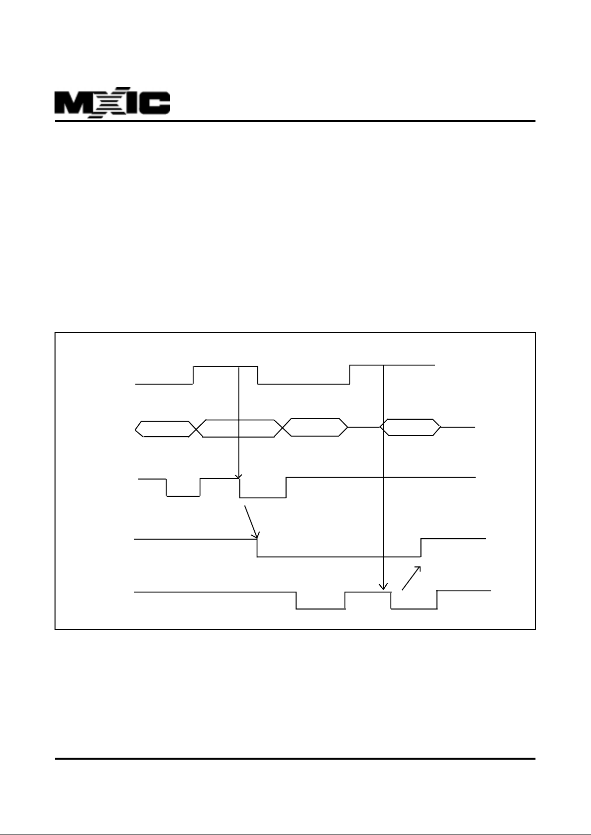
8-bit parallel :
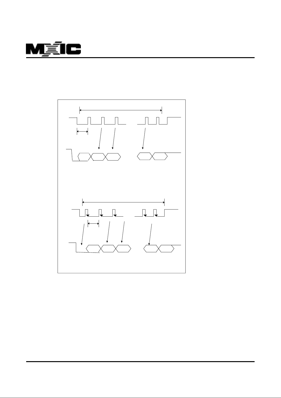
A 16-bit code can be accessed by HOST two times via setting PHILO pin. For writing operation, the HOST write the
low byte of the command into the register of DSP, when PHILO is pulled to low , DSP does nothing but latches data.
Following, PHILO is set to high and high byte of command is written into register , then DSP will perform the command
issued by HOST and send out the response. DSP will pull PACK\ to be low to indicate that response is ready . HOST
must read the low byte and then high byte sequentially. PACK\ will reset to high when the high byte is read b y HOST.
All of the description given above will be illustrated by the following timing chart.
PHILO
PHDB 0 - 7
PHWR\
PACKB\
PHRD\
Page 9
9
P/N:PM0689
REV. 1.0.3, DEC. 13, 1999
MX93032
Synchronous Serial :
The protocol of synchronous serial interface will be interpreted by the timing chart given below .
16 PULSES
SCLK
SI
Tget
16 PULSES
SCLK
SO
Tput
0 R15 R14 R1 R0
C15
C14
C1 C0START
0
…
…
…
…
Note: SCLK : synchronous clock sent by HOST,
SI : HOST serial in,
SO : HOST serial out,
Tget and Tput should be larger than 200 uS
Page 10

10
P/N:PM0689
REV. 1.0.3, DEC. 13, 1999
MX93032
Decision Rules between MCU mode and DSP Mode:
1 . The contents located on 0xE000 and 0xE001 are 0x1234 and 0x5678, It will be considered as external DSP mode.
This configuration is used for developing customer’s control codes on MXIC’s MX93032-M1 IC with standard
code.
2 . The contents located on 0x680E and 0x680F are 0x5678 and 0xA988, it will be considered as MCU mode. This is
the only one configuration for MCU mode under developing and mass production.
3 . Either the content located on 0x680E and not 0x5678 or that located on 0x680F are not 0xA988, it will be consid-
ered as DSP mode. The configuration is used for mass production f or DSP mode adopted.
4 . The decision priority depends on the items order. That is , the item labeled with smaller number has higher priority .
CONTROL CODE CONFIGURA TION (DSP MODE)
There are two configurations for customer development or production.
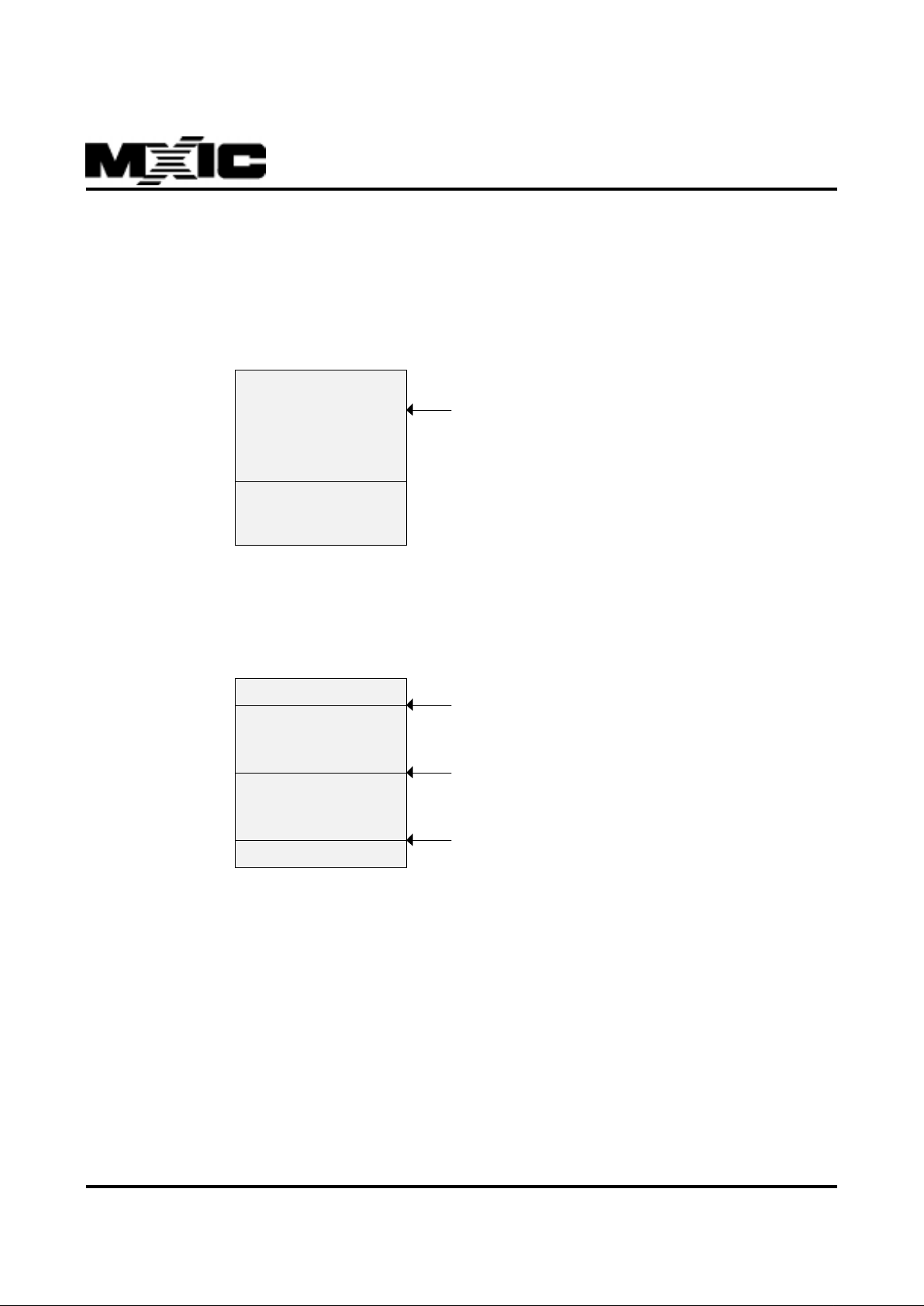
Configuration 1 :
In this configuration, the BIOS+ALGORITHM and control codes are all running in the external high-speed EPROMs
or SRAMs. The MX93032-M1 pin 97 (EROM) m ust be set to high.
26K words
6K words
0000H
6800H
7FFFH
External high-speed EPROMs or SRAMs
BIOS+ALGORITHM
c
(address 0000H - 67
F
cont rol co de
(address 6800H - 7F
This configuration is mainly used in the development stage and the access time of high-speed EPROMs or SRAMs
must be less than 30ns.
Page 11
11
P/N:PM0689
REV. 1.0.3, DEC. 13, 1999
MX93032
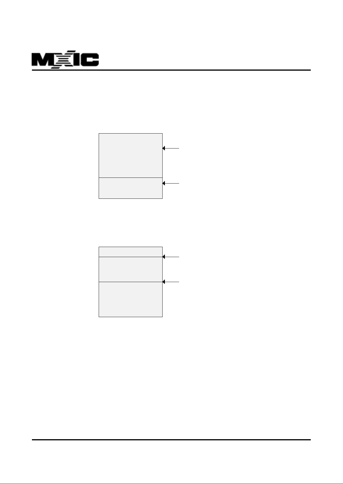
Configuration 2 :
In this configuration, the BIOS+ALGORITHM code is running in the MX93032-M1 internal ROM and the control code
running in the external low-speed EPROMs. The MX93032-M1 pin 97 (EROM) must be set to low .
26K words
0000H
6800H
7FFFH
DSP in t e rnal RO M
BIOS+ALGORITHM
c
(address 0000H - 67
F
Ext er n al l ow -sp e ed EPRO M s
0000H
E000H
FFFFH
ex t e rnal voi ce prom p
data address 1000H
ex t e rnal voi ce prom p
program address 80
0
1000H
max. 8K words
8000H
co ntrol code
(address E000H - F
F
This configuration can be used at the development stage or f or production. The control code must start with two words
1234H and 5678H.
Page 12
12
P/N:PM0689
REV. 1.0.3, DEC. 13, 1999
MX93032
Configuration 3 :
In this configuration, the BIOS+ALGORITHM and control codes are all running in the MX93032-M1 internal ROM. The
MX93032-M1 pin 97 (EROM) must be set to low .
26K words
6 K words
00 00H
6800H
7FFFH
DSP internal ROM
BIOS+ALGORITHM
c
(addres s 0000H - 67
F
cont rol co de
(addres s 6800H - 7F
0000H
8000H
FFF FH
External low-speed EPROMs
exter nal voice promp
data address 1000H
exter nal voice promp
program address 80
0
1000H
This configuration is used for production.
T o set the v oice prompt configuration, see the MX93032-M1 Mode 7.
Page 13

13
P/N:PM0689
REV. 1.0.3, DEC. 13, 1999
MX93032
MX93032-M1
The MX93032-M1 provides DSP embedded functional
modules, including speech compression/decompression,
telephone line signal processing, ROM voice prompt,
Macronix MX29F16A Flash management, time keeping
and full duplex speaker phone.
In MCU mode, the MX93032-M1 service is requested
via a command call with 16 bits parameter sent by Micro
controller, and answered 16 bits sent by DSP. In DSP
mode, user's system control program can be masked-in
the MX93032.
The MX93032-M1 supports 16 modes of service and
responses useful to operational information about timing, FLASH utilization, detected DTMF, etc.
Hereafter , HOST means "external micro-controller" f or
MCU mode, and it means "system control program"
for DSP mode.
FLASH MANAGEMENT
The MX93032-M1 uses MXIC's MX29F16A FLASH as
storage device for message and/or voice prompt data.
Up to two MX29F16A can be supported by the MX93032M1 service command.
The MX29F16A is a 16M-bit FLASH memory organized
as 1M word x 16. It includes 16 sectors (each sector is
64K words) and some of these sixteen sectors are bad.
T o manage the MX29F16A, the MX93032-M1 will detect
and then give up bad sectors and only utilize the good
sectors. For the purpose of storage efficiency , each good
sector is further divided into 32 blocks (each block contains 2K words). Each block can store speech data of
about 6.8 seconds for 4.8kbps compression algorithm
and 2.55 seconds for 12.8kbps compression algorithm.
MESSAGE RECORDING AND ST ORAGE
The MX93032-M1 provides high quality speech compression techniques for recording and playback functions. It
can permit over 15 minutes or 40 minutes of speech
storage in each 16M bit of MXIC's MX29F16A FLASH
device based on 12.8K or 4.8K compression rate, respectively.
The MX93032-M1 supports up to 127 variable length in-
coming and outgoing messages that are labeled as Msg
ID 1 to 127. Although ICM could range from Msg 1 to
127, Msg IDs 127 to 121 are the only places for outgoing
messages (OGM) storage so that the deletion and recovery of old OGM are easier to maintain. The Msg IDs
of incoming messages are labeled chronologically and
rearranged automatically after recording or deleting. ICM
with Msg ID 1 is the oldest recorded incoming message.
Each message can be recorded by either 4.8K or 12.8K
compression rate depending on system programmer’s
assignment.
During recording, the MX93032-M1 also monitors the
telephone line signal to detect the presence of DTMF,
Call Progress Tone and Continuous T one and responses
to the control program. The HOST can stop recording,
and delete the last n*400ms/200ms from the memory
using a Record command with assigned Tail Cut factor.
The MX93032-M1 can generate a desired tone during
recording voice message, which allows the application
such as two-way recording. During recording, Record
Pause function is provided.
The recording voice signal, received through the CODEC
input, is transmitted back to the CODEC output by the
MX93032-M1 service commands.
OUTGOING MESSAGE (OGM) RECORD
The MX93032-M1 provides flexible recording ways for
outgoing message. The HOST can select to delete the
old OGM before a new one is recorded or to abort the
new OGM record without losing the old OGM.
NEW/OLD MESSAGE
For the control program to manipulate incoming messages more handily , the MX93032-M1 keeps an internal
record of the ICM to identify the new/old status of messages.
Before playback, the status of ICM is considered as
"new". All incoming messages that have been played
could change their status to "old" by issuing Real Del bit
on Delete command. After Real Del is issued, all new/
old ICM Msg IDs will be rearranged. The functions , Play
New or Delete All Old messages , are provided by the
MX93032-M1 in the command set.
Page 14

14
P/N:PM0689
REV. 1.0.3, DEC. 13, 1999
MX93032
MESSAGE PLAYBACK
Random access for playback of any new message or
message with specified Msg ID is supported by the
MX93032-M1. During playback, the MX93032-M1 also
monitors the telephone line signals, and Play P ause function is provided. The MX93032-M1 is ab le to fast-forw ard
the playback of a recorded message, and the playing
speed will be up to 33 %.
MESSAGE DELETION
The MX93032-M1 provides two ways to delete recorded
ICMs. One is the two-step method - the combination of
Del Mark and Real Del on Play and Delete command,
and the other is the immediate method - Delete command. The two-step method enab les the control program
to handle the deletion more flexibly, while the immediate
method deletes a specified message directly .
VOICE PR OMPT
For high-quality voice prompt playback, the MX93032M1 utilizes the built-in speech decoder and external
EPROM/ROM or FLASH to store the vocabulary. The
MX93032-M1 also supports up to a 32K-word external
EPROM/ROM that allows minimum 1.8 minutes of voice
prompt storage. If voice prompt data is stored in FLASH,
space of maximum 60K words (minimum 3.4 minutes) is
permitted. The external (upper part) voice prompt is also
allowed. But if FLASH voice prompt is enabled, the external voice prompt will be disabled. The v ocabulary supports up to 255 phrases. Giv en a phrase number in the
V oice Prompt command from the HOST, the MX93032M1 outputs the corresponding utterances to the Codec
interface. The starting address of external voice prompt
data could be located at data address 1000H, or program address 8000H.
During playback of the voice prompt, the MX93032-M1
monitors the telephone line signals.
PERSONAL MAIL
The MX93032-M1 supports up to 8 mailboxes that may
be used for personal mail application. Each mailbox has
its own ICM/MEMO Msg ID . The total Msg.ID is 127 for
all of mailbox. Before recording, playing or deleting mes-
sages, the HOST should set the corresponding mailbox
number first with Personal Mail command.
TIME KEEPING
There is a timer clock in the MX93032-M1. The HOST
can issue Set Time and Get Time commands to get time
services. The cloc k also supports system to stamp time
to the recorded incoming message.
DTMF DETECTION
For remote control operation of the answering machine,
the MX93032-M1 monitors the incoming telephone line
signal to detect the presence of DTMF signal.
TONE GENERA TION
Up to double tones can be generated by the MX93032M1. The levels and frequencies are programmable by
the HOST .
CALL PROGRESS T ONE DETECTION
The MX93032-M1 supports the detection of call progress
tone within the band of 300 - 640 Hz for the incoming
telephone line signal. The tone detector is implemented
with a bandpass filter. Indication of the presence of call
progress tone is responded to the control program, and
could be used to terminate recording.
NEAR END ECHO CANCELLA TION
The MX93032-M1 implements a near end echo canceller in software to enhance the detection of DTMF and
Call Progress Tone during Playback and Voice Prompt
mode.
FSK Decoder
All of the services, Calling Number Delivery (CND), Calling Name Delivery (CNAM) and Calling Identity Delivery
on Call Waiting (CIDCW), exploit the Frequency Shift
Keying (FSK) method to tr ansmit the desired data from
the SPCS to CPE. Depending on the specific service,
Page 15

15
P/N:PM0689
REV. 1.0.3, DEC. 13, 1999
MX93032
data transmission may occur with the CPE in an onhook state or in an off-hook state. The specifications f or
data transmission are given on SR-TSV-002474 which
are classified into three layers, ph ysical lay er, data link er
layer and message assemble layer. The MX93032-M1
only takes the responsibility to decode physical layer.
For Data link layer (Check Sum) and Message Assemble
layer (the meaningful data), system should take care.
The performance test associated with physical layer
based on SR-3004 will be given on Appendix A.
Note: CPE: Custom Premises Equipment
SPCS: Stored Program Controlled Switching
System
CAS Detection
For Calling Identity Deliv ery on Call Waiting, the MX93032M1 will monitor the presence of CPE alerting signal according to the specification given on Bellcore Special
Report SR-TSV-002476.
VOX DETECTION (DIGITAL VOICE ACTIVATED RECORDING)
The speech detection is implemented on the MX93032M1 to indicate whether the recording signal level is above
the VOX threshold. If the control prog r am sets the VO X
Record bit on Initial command, the recording of the speech
would start when the voice activity is detected. The HOST
has to set V O X threshold by issuing command Mode 13.
Hexadecimal numbers f or V OX threshold are listed in T able
6.
SPEAKERPHONE
The speaker system provided by the MX93032-M1 contains two adaptive filters which are called as acoustical
echo canceller (AEC) and line echo canceller (LEC). The
purpose of AEC is used to cancel the acoustical echo
between microphone and speaker which is caused by
the sound reflection within space. A LEC cancels the
echo resulted by the 4 to 2 wire telephone line connection and impedance mismatches between customer premises and the central office.
When speakerphone is activated, the algorithms associated with AEC and LEC not only reduce the echo heard
on the both ends, but also prevent feedback instability
(singing) from occurring. Moreove r, the MX93032-M1 provides automatic gain control (AGC) for microphone channel which helps the outgoing voice to keep at a desired
level especially f or a moving talk er, and speak er volume
control which allows the user to adjust the speaker volume for his need. In addition, DTMF/Tone generations
and call-progress tone detection are also provided.
Page 16
16
P/N:PM0689
REV. 1.0.3, DEC. 13, 1999
MX93032
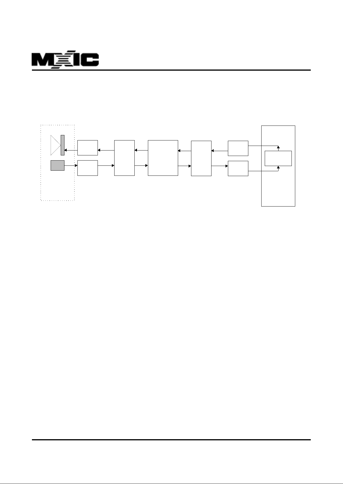
DAA CONSIDERA TION FOR SPEAKER PHONE
It should be emphasized that DAA circuit pla ys an important role on improving the performance of speakerphone. This
sub section gives some guides on how the D AA circuit may be "tuned". A diagram of D AA circuit must be given for
simplifying the flowing interpretation.
Referring to figure given above, we have 4 analog amplifiers which are
1.Microphone Pre-Gain (MIC GAIN)
2.Line Out Gain (LINE DRV)
3.Line in Pre-Gain (LINE GAIN)
4.Speaker amplifier (SPK DRV)
Obviously, the 4 amplifiers together with the Line Out volume, Speaker Volume, receive attenuator , transmit attenuator, two volume compensators, acoustical coupling function Hac(f) and line coupling function Hlin(f) compose a
closed loop system. The AEC and LEC will pro vide additional attenuation to the loop gain one they con verge .
To have a better performance on speaker phone, w e strongly recommend that analog gain of D AA must satisfy the
following two criteria:
1.As the near end (Microphone side) speaks only , the lev el at Codec 2 should fulfill that, "codec 2 input must
be less than Codec 2 output due to electrical echo". This meaning can be e xpressed as
LINE_DRV * Hlin(f) * LINE_GAIN < 1
2.As the far end (Line Side) speaks only, the level at Codec 1 should fulfill that, "Codec 1 output must be
greater than Codec 1 input resulting from acoustical echo". This meaning can be expressed as
SPK_DRV * Hac(f) * MIC_GAIN < 1
By considering the criterion 1, it should pay more attention that minimum echo should be reached by improving the
telephone line interface ( that is, reducing Hlin(f)) and not by reducing LINE_GAIN due to that the MX93032-M1 must
obtain the high enough signal to process. For the same reason for criterion 2, the low echo should be achieved by
good acoustical and mechanical decoupling rather than by decreasing MIC_GAIN.
The ultimate target for hardware design is to create one system which not only satisfies two criteria given above, but
also provides a desirable volume to both speaker and telephone.
CODE C1
MX93032-M1
SPK
DR V
MIC
GAIN
AC OU STIC
COUP L ING
CODE C2
LINE
GAIN
LINE
DR V
4 - 2 WIRE
COUPLING
LINE
COUPLING
Page 17

17
P/N:PM0689
REV. 1.0.3, DEC. 13, 1999
MX93032
QUER Y AND REPORT
The MX93032-M1 is capable of reporting to the control program about the query of the current status , such as the
number of recorded messages, the number of new messages, the number of old messages, the available recording
time of FLASH, the time of recorded message, and the FLASH good/bad check.
POWER DO WN
With the power of backup batteries, the MX93032-M1 is capable of keeping messages and data stored in the FLASH
during power failure. In power down mode, the MX93032-M1 will run at a lower clock rate to reduce power consumption.
CRYST AL CONNECTION
The MX93032-M1 allows two ways of crystal connections :
1. Normal approach: use both high crystal (32.256 MHz) and low crystal (32768 Hz). T o enab le this mode, the FLLEN\
(54) pin must be connected to VDD. In this mode, the DSP high clock is gener ated from the high crystal directly,
and the low crystal is mainly used in power down mode.
2. FLL (F requency-Lock ed-Loop) approach: use only low crystal (32768 Hz). To enable this mode, the FLLEN\ (54) pin
and X2 (89) pin must be connected to ground and the X1 (88) pin to VDD . In this mode , the low crystal is to generate
all the DSP system clocks and the high crystal can be saved to reduce the overall system cost.
Page 18

18
P/N:PM0689
REV. 1.0.3, DEC. 13, 1999
MX93032
7.0 OPERATIONAL DESCRIPTIONS
When the system is powered up, the RST\ pulse will make the MX93032-M1 to run programs from address 0. After
check sum of internal ROM codes checked and some essential initialization of DSP are finished. In MCU mode, the
MX93032-M1 is ready to poll the command issued by the HOST and indicate the HOST by setting PACK\ or SI\ to be
low . The HOST should poll the indication sent b y the MX93032-M1 and read out the pseudo response first. F ollowing
some necessary initialization given below must be set by HOST .
1. Set telephone data configuration
2. FLASH initialization depending on the FLASH good/bad check
3. Codec initialization if necessary
4. Setting V oice prompt configuration
5. Setting Silence threshold
6. Setting VO X level
8.0 MODES OF OPERATION
The MX93032-M1 supports 16 modes of operations, which are listed as follows :
Command Mode Mode Name
0 Idle Mode
1 Record
2 Play
3 Message Status
4 DTMF Generator
5 Line Monitor
6 Delete Message
7 Set Current Time/Voice Prompt/Silence Threshold
8 Get Current Time
9 Initial and Test Memory
10 Get Record Message Information
11 V oice Prompt
12 Speaker Phone
13 Personal Mail
14 T elephone Data
15 CAS Detection
Page 19

19
P/N:PM0689
REV. 1.0.3, DEC. 13, 1999
MX93032
IDLE :
This command is allowable to be issued within any other operation which is processing. As soon as the MX93032-M1
receives Idle command, the original operation will be stopped automatically .
RECORD
When Record command is received from the HOST, the MX93032-M1 performs speech compression, stores the
message into FLASH, and monitors telephone line. If the V O X Record bit had been set to 1 on Initial and Test Memory
command, recording of the speech will start upon the voice activity detected, else the MX93032-M1 starts recording
immediately after Record command is received.
Clearing Marked Record (bit 8-10) to 0, if it is recording ICM. When recording OGM, the HOST should set Marked
Record (bit 8-10) to desired number other than 0 as OGM ID .
Setting bit 5 (Annc Del) to 1 on Initial and Test Memor y command, the HOST can choose to delete the old OGM
before a new one is recorded. If that bit is cleared to 0, the ne w OGM recording can be aborted without losing the old
OGM by issuing Mark Fail (bit 11) on Record command.
During recording, the HOST can pause the recording by setting Pause (bit 7) to 1 and resume recording b y clearing
that bit. Line monitoring will continue during pause.
The HOST can stop recording by setting Stop (bit 6) to 1, and delete the last n*400ms/200ms from the memory by
using a Record command with assigned Tail Cut factor (bit 0-5).
While system memory is full, MX93032-M1 will stop message recording, show the status in response word (bit 7,
Mfull).
During Record mode, the HOST can instruct the MX93032-M1 to generate a tone by issuing the DTMF Generator
command. Setting Stop bit on DTMF Generator command will stop tone generating.
The MX93032-M1 will terminate Record mode when Stop bit on Record command is set to 1.
Note: The MX93032-M1 supports up to 127 incoming and outgoing messages recording which are labeled as Msg ID
1-127. The Msg IDs of incoming message are labeled chronologically and rearranged automatically after recording. Although ICM could range from Msg ID 1 to 127, Msg IDs 127 to 121 are the only places for outgoing
message storage. So, it is strongly suggested that the HOST should keep an upper bound of the number of
ICM. (For example, upper bound of ICM = 127 - maximum OGM number that will be applied in user's specification.)
PLA Y
When Play command is received from the HOST, the MX93032-M1 performs message playback and line monitoring.
The Msg ID (bit 0-6) is set by the HOST to specify which message to play. To playback new message (non-played
one), set Play New (bit 10) to 1, then the MX93032-M1 will search to play the non-played message with specified Msg
ID. During playing, the HOST can pause playback by setting Pause (bit 8) to 1 and resume playing from the same
point by clearing that bit. Line monitoring will continue during pause. To fast playback a recorded message, set Fast
Play (bit 11) to 1 and the playing speed will be up to 33%.
Page 20

20
P/N:PM0689
REV. 1.0.3, DEC. 13, 1999
MX93032
To delete and stop the playing message, the HOST can set Del Mark (bit 7) on Play command. After being tagged a
"Del Mark" the marked message is not really deleted until a Real Del (Delete Message mode bit 8) is set. The Real Del
command not only deletes the messages that have been tagged a "Del Mark" but also changes the status of those
ICMs that have been pla yed to old. The ICMs that ha ve not been play ed before are regarded as "new". After Real Del
is issued, all new/old ICM Msg IDs will be rearranged.
For the HOST, it is used to issue the Real Del after the user terminates the manner of playback.
The response word contains the information of tones detected from the line, playing time spent (bit 8-15) and End of
play flag (bit 6), which indicates the end of the current message. When the Pla y End bit is 1, the MX93032-M1 stops
playback.
The MX93032-M1 will terminate Play mode when Stop bit or Del Mark bit is set to 1 on Play command.
MESSAGE ST ATUS
In this mode, there are 6 request codes for the HOST to get message information;
1. Get the number of personal recorded messages (request code = 0)
2. Get the number of personal new messages (request code = 1)
3. Get the number of personal old messages (request code = 2)
4. Get the available recording time with unit of second (request code = 3)
5. Get the number of total recorded messages (request code = 8)
The result will be reported in the response word.
DTMF GENERA TOR
In this mode, up to double tones can be generated by the MX93032-M1. The tone levels and frequencies are programmable and controlled by the HOST. The DTMF Gener ator command defines the output gains in bit 0-3 for the 1st tone,
and bit 4-7 for the 2nd tone. Each tone can be programmed from 3 dB (gain code 0000) to -25 dB (gain code 1110) with
2 dB resolution. For DSP mode, the frequencies are defined in the variables BUF1 and BUF2. For MCU mode, three
steps of commands should be issued, first, DTMF sent and signal Gain should be set, following the corresponding
two frequencies should be specified. The frequency code and its frequency represented is according to the f ollowing
relationship :
frequency code = desired frequency (Hz) * 8.19
f(n) = 32767 * cos (2*pi*f_code*n/(8000*8.19))
where f_code is the input frequency code, n is sequence index and 8000 is the sampling rate
For single tone, Codec outputs the signal s(n) :
s(n) = gain * f(n)
For dual tone, Codec outputs the signal s(n) :
s(n) = 0.5 * (gain1*f1(n) + gain2*f2(n))
To generate a single tone, the gain code of the other tone should be set to 1111. The MX93032-M1 star ts tone
generation only after receiving the start command.
The MX93032-M1 will terminate DTMF Generator when Stop bit is set to 1 on DTMF Generator command.
Page 21
21
P/N:PM0689
REV. 1.0.3, DEC. 13, 1999
MX93032
LINE MONITOR
In this mode the MX93032-M1 monitors the telephone line signal for the detection of DTMF, Call Progress Tone, V O X,
and/or Continuous Tone. The MX93032-M1 keeps monitoring the line until Stop bit is set to 1.
The MX93032-M1 returns to the HOST a response word that reflects the flag of Call Progress Tone, VO X, Continuous
Tone and the index of DTMF signal that has been detected :
INDEX DTMF CODE INDEX DTMF CODE
CAS DTMF CAS DTMF
0 0000 No T one 0 1001 9
0 0001 1 0 1010 *
0 0010 2 0 1011 0
0 0011 3 0 1100 #
0 0100 4 0 1101 A
0 0101 5 0 1110 B
0 0110 6 0 1111 C
0 0111 7 1 1111 D
0 1000 8 1 0000 CAS TONE
The MX93032-M1 will terminate Line Monitor mode when Stop bit is set to 1 on Line Monitor command.
DELETE MESSAGE
This mode provides an immediate way to delete messages as follows;
1. To delete a specified message, set its Msg ID in bit 0-6 and clear bit 11, 10 and 7 to zero.
2. T o delete a specified ne w ICM, set Del New Msg (bit 10) to 1, give the New Msg ID in bit 0-6, clear bit 11, 7 to z ero.
3. To delete all old ICM, set Del All Old (bit 7) to 1 and clear bit 11, 10 to zero. (Bit 0-6 is ignored)
4. T o erase the "Del Mark" from a specified ICM ("Del Mark" is a tag set on Play command f or deletion), set Del Mark
Clr (bit 11) to 1, give the Msg ID in bit 0-6 and clear bit 7 to zero .
SET CURRENT TIME/V OICE PROMPT/SILENCE THRESHOLD
In this mode the HOST can set the current time to the timer clock of the MX93032-M1. The time inf ormation includes
second, minute, hour and week. The timer in the MX93032-M1 will be used to stamp time and data to the recorded
message.
1. To set second, put the data in bit 0-7 and use request code (bit 8-11) 0000.
2. To set minute, put the data in bit 0-7 and use request code (bit 8-11) 0001.
3. To set hour, put the data in bit 0-7 and use request code (bit 8-11) 0010.
4. To set week, put the data in bit 0-7 and use request code (bit 8-11) 0011.
5. To set voice prompt configuration, put the selection data in bit 0-1 and use request code (bit 8-11) 0110.
6. To set silence threshold level, put the data in bit 0-3 and use request code (bit 8-11) 0111.
7. T o set output port OPT0-7, put data in bit0-7(Request Code=0100)
8. T o set codec MX93002 registers in bit10-8 and put data in bit0-7(Request Code=1xxx)
9. To write link index and data in bit0-7(Request Code=0101), refer to mode10 to specify Msg. ID .
Page 22

22
P/N:PM0689
REV. 1.0.3, DEC. 13, 1999
MX93032
GET CURRENT TIME
In this mode the HOST can get the current time from the timer clock of the MX93032-M1. The time infor mation
includes second, minute, hour and week.
1. T o get second, use request code (bit 8-11) 0000.
2. To get minute, use request code (bit 8-11) 0001.
3. T o get hour , use request code (bit 8-11) 0010.
4. T o get w eek, use request code (bit 8-11) 0011.
The requested data will be reported in the response word.
INITIAL AND TEST MEMOR Y
In this mode there are 9 functions for the control program to define;
1. FLASH Re-Initialization
The HOST can re-initialize the FLASH by setting FLASH Re-Init (bit 0) to 1. After receiving this command, the
MX93032-M1 will erase all the messages and data stored in the FLASH and then re-format the FLASH to establish
the management structure. The response word reported to the control program contains the information of FLASH bit
size (bit 0-3) , FLASH address size (bit 4-7), FLASH good/bad status (bit 8) and FLASH good rate (bit 9-15). After reinitialization, all messages and data in the FLASH are lost.
2. FLASH Initialization or Error Correction
The HOST can perform FLASH first-time initialization or error correction by setting FLASH Init (bit 1) to 1. First-time
initialization is to format a new FLASH and then establish the management structure, while error correction is to
correct the problems that may result from pow er loss during operation. This function is normally used after first powerup of the system. The response word reported to the control program contains the inf ormation of FLASH bit size (bit
0-3) , FLASH address size (bit 4-7), FLASH good/bad status (bit 8) and FLASH good rate (bit 9-15).
3. FLASH Garbage Collection
Due to the characteristics of MX29F16A FLASH and the management structure, when messages are deleted, the
data regions occupied by them will not be released to be av ailable immediately . To free out such regions, the MX93032M1 provides a two-step mechanism. First is to check the FLASH garbage collection recommendation status by
Message Status command and, if garbage collection is recommended, then to issue bit 2 (Garbage Collect) on this
command to perform the corresponding garbage collection actions.
4. Line On/Off
The HOST should set Line On/Off (bit 3) to 1 if the system is logged in from telephone line, and clear that bit to 0 if
in local keypad operation. Failing to set this bit properly will degrade the performance of echo cancellation.
5. V O X On/Off Record
If the HOST turns on the V OX Record function (b y setting bit 4 to 1) on this command, speech recording will start upon
the voice activity detected, else recording will start immediately after Record command is issued.
Page 23

23
P/N:PM0689
REV. 1.0.3, DEC. 13, 1999
MX93032
6. OGM Deletion
By setting bit 5 (Annc Del) to 1 on this command, the HOST can choose to delete the old OGM before recording a new
one. If that bit is cleared to 0, the old OGM is not deleted until the new OGM recording is completed. With this option,
the new OGM recording can be aborted without losing the old OGM by issuing Mark Fail (bit 11) on Record command.
7. New/Old Select
By setting New/Old Select (bit 6), the HOST can decide which condition a new message will be changed to an old one.
There are two options. When this bit is set to 1, the new message that has been played (even not played end) is
regarded as an old message. If this bit is cleared to 0, the new message that has been played end is regarded as an
old one.
8. Tail Cut Unit
By setting Tail Cut Unit (bit 7) to 1, the HOST can choose the tail cut unit length to be 200 ms. If this bit is cleared to
0, the unit length is 400 ms.
9. Old Mark Set
By setting Old Mark Set (bit 8) to 1, the HOST can disable that new messages change to be old ones even though
they have been played (end). If this bit is cleared to 0, new to old change will be enabled and the change criterion is
according to the setting of New/Old Select bit (bit 6).
GET RECORD MESSAGE INFORMA TION
In this mode, there are 10 request codes for the control program to get the related information about a specified
message.
Given the Msg ID (bit 0-6) and New Msg flag (bit 7), the MX93032-M1 can provide message recording time, recording
length, attribute and "Del Mark" status according to the Request Code (bit 8-11) as follows :
1. Get the recording time - second. (Request Code = 0000)
2. Get the recording time - minute. (Request Code = 0001)
3. Get the recording time - hour. (Request Code = 0010)
4. Get the recording time - week. (Request Code = 0011)
5. Get the recording length (sec.). (Request Code = 0100)
6. Get the timer status. (Request Code = 0101). The response word is 1 if the MX93032-M1 timer has been set before
with Set Current Time command. Otherwise, the response w ord is 0.
7. Get the message ICM/MEMO attribute. (Request code = 0110). T o sho w the specified message is of MEMO type
(response word = 1) or ICM type (response word = 0).
8. Get the Del Mark status (Request Code = 0111). To check if the specified message has been tagged a Del Mark
(response word = 1) or not (response word = 0).
9. Get the message new/old status. (Request Code = 1000). To check if the specified message has been tagged an
Old Mark (response word = 1) or not (response word = 0). A new message will be tagged an Old Mark when it has
been played/played end and changes to old messages as Real Del command is issued.
10.Get the OGM existing status (Request Code = 1111). To check if the specified OGM exists (response word = 1) or
not (response word = 0). Msg ID could only range from 127 to 121.
11.T o get link index data(Request Code=1001),refer to mode7
12.T o set the Msg. ID for reading/writing Link-index-data.(Request Code=1010)
All the results are reported in the response word.
Page 24

24
P/N:PM0689
REV. 1.0.3, DEC. 13, 1999
MX93032
VOICE PROMPT
In this mode the MX93032-M1 plays back a speech segment that the corresponding phrase number is given in
command bit 0-7. Up to 255 speech segments , previously stored in voice prompt R OM or Flash memory , are provided
by the MX93032-M1 and pronounced using the speech decompression algorithm. The HOST can pause the playbac k
by setting Pause (bit 8) to 1 or resume from pause b y clearing Pause bit to 0. Fast forward playback of v oice prompt
is also provided by setting F ast Play (bit 11) to 1. During Voice Prompt mode, the MX93032-M1 keeps monitoring the
line signal and sends the results in response word to the control program.
The MX93032-M1 will terminate Voice Prompt mode when Stop bit is set to 1 on V oice Prompt command.
SPEAKERPHONE
Regarding to speakerphone related function is comprised of three types which are parameter setting, DTMF/Tone
generation and free run. Two Codecs are necessary for speakerphone operation. One Codec labeled as Codec 1 is
used for microphone and speaker , and the other labeled as Codec 2 is used for telephone line input and output. In this
mode, there are seven functions whose detail will be given as follows:
1. Free run which performs both filtering operation and updating operation on LEC and AEC one time for each Codec
interrupt triggered (Request Code = 0x0000)
2. Setting the gain for DTMF/T one generation (Request Code = 0x0001)
3. Generating DTMF/T one according to pre-defined table (Request Code = 0x0010)
4. Setting both the echo return-loss on speaker side (ERL_AEC) and echo return loss on line side (ERL_LEC)
(Request Code = 0x0100)
5. The T/R and R/T ratio are used to decide which side is speaking by comparing the transmitting and receiving
energy .(Request Code=0x0110)
6. Set the volume gains to control the speaker out and line out signal levels(Request Code=0x1000)
7. The loop attenuation is to control the total receive and transmit attenuators (Request Code = 0x1001)
8. setting the tone table which require 3 steps : Index set, F req_Lo set and F req_Hi set.
PERSONAL MAIL
Five functions are provided in this command as follows :
1. Set the personal mailbox number
In this mode the HOST can select one out of eight mailboxes (setting in bit 0-2) for recording messages, playing
recorded messages and retrieving message time. Each mailbox manages its own messages and Msg IDs.
Make sure to set the desired mailbox bef ore issuing the message related commands such as Record, Pla y, Delete
Message and Get Record Message Information.
2. Set the recording message attribute
Before recording a message, the HOST can set the attribute of that message to be MEMO or ICM. Clear bit 3 to zero
for recording a message as an ICM or set bit 3 to one for recording a message as a MEMO .
3. Set the digital loop back control
The HOST can enable or disable the DSP digital loop back path in Record or Line Monitor operation. By setting Loop
Back bit to 1, the loop back path is disabled and the signal received from the codec input will not be transmitted back
Page 25

25
P/N:PM0689
REV. 1.0.3, DEC. 13, 1999
MX93032
to the codec output. When this bit is cleared to 0, loop back is enabled and the receiv ed signal will be transmitted back
to the codec output. The default status is the latter.
4. Set the output level
The HOST can set the level difference between the output (playback) speech and the corresponding input (recordedin) speech. By setting the Output Level bit to 1, the output speech level is equal to the input speech level, and clearing
this bit to 0, the output speech level is about 5dB less than the input speech level. The default status is the latter.
5. Set the codec data format
The HOST can select one of two Codec data formats by setting the Codec Format bit. When Codec F ormat is cleared
to 0, 8-bit m-law data format is selected, and set to 1, 16-bit linear data format is enabled. At present, MXIC’s Codec
family provide both m-law and linear f ormats, and the latter is suggested because of the better speech quality. The
default format is 8-bit m-law.
6. Set Voice Activity
In this mode the HOST can set the VOX threshold in bit 0-11. The hexadecimal numbers for VOX le vel are listed in
T ab le 6.
7. Set Telephone Data Configuration
This command should be issued before Aflash initialization.
CAS Detection
The MX93032-M1 provides 2 output modes for CAS detection, which are continuous response and one time response.
For continuous response, the MX93032-M1 will respond CAS detected after 45± 5ms since CAS occurs in CPE.
Regarding to response one time, the information of CAS detected will be responded after both the CAS is disappeared
on the line and the duration for CAS appearance between 45ms to 95 ms.
FSK Detection
The output of FSK detector can be divided into two mode which are Raw data mode and Cooked data buffer. The
buffer length f or Ra w data mode and Cooked Data mode are 8 b ytes and 60 bytes long, respectiv ely. For Raw data
mode, the data ready bit will be set on one bytes data ,in which start bit and stop bit are not included, received
correctly . If the host’ s speed can not catch up the FSK baudrate , buffer ov erflow will occur . Therefore , when the serial
interface is adopted, we do not recommend to select Raw data mode to receive FSK data. Cooked data mode
concerned, the data ready bit will be set after all of the data, in which checksum is included, received. During the
operation for Cooked data mode, the second data byte following the mark data will be considered as the total data
length, the other data will not be recognized by MX93032-M1.
LINKAGE BETWEEN CID D A T A AND V OICE MESSAGE
1. Set the link index which can be also considered as CID data number (Request code = 0x7500 | link index)
2 . Get the link index (Request code = 0xA900 | msg_no)
3 . write the link index specified by 0x7500 into message (Request code = 0xAA00 | msg_no)
Page 26

26
P/N:PM0689
REV. 1.0.3, DEC. 13, 1999
MX93032
TELEPHONE DA T A
In this mode the HOST can write/read telephone or user-assigned data to/from the FLASH with the sequence of
telephone data command as follows :
1. Write T elephone Data
The first command defines the telephone record ID (bit 0-7) and set bit 11, 10 to 0, 0.
Following command specifies the one-byte data to be stored under that ID.
While the current record ID is full, the MX93032-M1 BIOS will show the status in response word (bit 0, Full).
The MX93032-M1 BIOS will terminate Telephone Data mode when Stop (bit 9) is set to 1 on Telephone Data command.
2. Read Telephone Data
The first command defines the telephone record ID (bit 0-7) and set bit 11, 10 to 0, 1. The telephone data will be put
on the response word. Following command puts the one-byte data on the response word to the control program.
The response word contains the byte-data (bit 0-7) and Read End (bit 8). When the Read End bit is 1, the byte-data is
invalid.
The MX93032-M1 BIOS will terminate Telephone Data mode when Stop (bit 9) is set to 1 on Telephone Data command.
If host want to write/read more than 2 Tel. Record IDs at the same time, Before writing/reading an ne w T el. ID, host
should set STOP bit to 1 f or the current T el. ID.
Page 27

27
P/N:PM0689
REV. 1.0.3, DEC. 13, 1999
MX93032
9.0 COMMAND FORMAT AND PROTOCAL
Mode 0. IDLE MODE
(15-12)
0000
CONF
00000000000
0000000000000000
0000000000000000
STOP
(11-1)
0
(15-12)
RESP
(11-1)
0
Mode 1. RECORD MODE
(15-12) (11) (10-8) (7) (6)
0001
MARK
FAIL
MARKED
RECORD
P A USE STOP
CONF
TAIL CUT
(5-0)
TAIL CUT : 0 ~ 63 units. One unit length can be 400ms or 200ms (set by Mode 9).
ST OP = 1 : stop recording.
PAU SE = 0 : continue recording.
= 1 : pause recording.
MARKED RECORD
= 000 : record a general message.
= 001 : record OGM1 and store it in message 127.
= 010 : record OGM2 and store it in message 126.
= 011 : record OGM3 and store it in message 125.
= 100 : record OGM4 and store it in message 124.
= 101 : record OGM5 and store it in message 123.
= 110 : record OGM6 and store it in message 122.
= 111 : record OGM7 and store it in message 121.
MARK FAIL =1 : give up and stop recording of the new OGMx and recover the original OGMx. If Mode 9 ANNC
DEL=1, this bit will be ignored.
When MARKED RECORD = 000, do not set this bit.
Page 28

28
P/N:PM0689
REV. 1.0.3, DEC. 13, 1999
MX93032
(15-9) (8) (7) (5)(6) (4)
RECORD TIME (sec) CAS MFULL
VOX
TONE
CONT
TONE
RESP
DTMF
(3-0)
DTMF : the detected DTMF value during recording.
CONT TONE = 1 : continuous tone is found.
T O NE = 1 : call progress tone is found.
VOX = 1 : the input speech po wer le v el is under the VOX LEVEL (set b y Mode 12).
MFULL = 1 : ARAM is full and no further recording is possible. In this case, one more
STOP command is needed to completely stop the recording action.
RECORD TIME : recording time until now, 0 ~ 127 sec.
CAS : CAS detection for CIDCW (detail see mode 15 )
If CAS tone and DTMF D are existed at the same system, the Host should Check if bit8(CAS) == 1
and bit3-0(DTMF) =0000, and then that's a real CAS Tone. Refer to the f ollowing table .
DTMF Reference T able:
INDEX DTMF CODE INDEX DTMF CODE
CAS DTMF CAS DTMF
0 0000 No Tone 0 1001 9
0 0001 1 0 1010 *
0 0010 2 0 1011 0
0 0011 3 0 1100 #
0 0100 4 0 1101 A
0 0101 5 0 1110 B
0 0110 6 0 1111 C
0 0111 7 1 1111 D
0 1000 8 1 0000 CAS TONE
Page 29

29
P/N:PM0689
REV. 1.0.3, DEC. 13, 1999
MX93032
Mode 2. PLAY MODE
(15-12) (11) (10) (9) (8) (7)
0010
FAST
PLA Y
PLA Y
NEW
P AUSE STOPSTOP
CONF
MSG ID
(6-0)
(15-9) (8) (7) (5)(6) (4)
PLA Y TIME (sec) CAS 0
PLA Y
END
TONE
0
RESP
DTMF
(3-0)
MSG ID = 1 ~ 127 can be assigned for playing.
DEL MARK = 1 : stop playing and mark the current message with a "Del Mark". This message will not be deleted
until the Mode 6 REAL DEL command is done.
PAU SE = 0 : continue playing.
= 1 : pause playing.
ST O P = 1 : stop playing.
PLAY NEW = 0 : the MSG ID is related to total messages.
= 1 : the MSG ID is related to new messages.
F AST PLAY = 0 : normal play speed.
= 1 : play speed will be up to 33%.
DTMF and T ONE : see RECORD MODE.
PLA Y END = 1 : the current message is played end.
PLAY TIME : playing time until now, 0 ~ 239 sec.
CAS : CAS detection for CIDCW (detail see mode 15 and mode1)
Mode 3. MESSA GE ST ATUS MODE
(15-12)
0011
CONF
00000000000
DATA
REQUEST CODE
(11-4)
(15-0)
(3-0)
RESP
REQUEST CODE:
REQUEST CODE STA TUS D A TA
0000 number of personal total messages 0 ~ 127
0001 number of personal new messages 0 ~ 127
0010 number of personal old messages 0 ~ 127
0011 available time 0 ~ 65535
0101 garbage collection recommendation 0 or 1
1000 number of total messages 0 ~ 127
Page 30

30
P/N:PM0689
REV. 1.0.3, DEC. 13, 1999
MX93032
Mode 4. DTMF GENERA T OR MODE
For DSP mode:
GAIN1, GAIN2 : 0 ~ 14 denote 3dB ~ -25dB (2dB/one step), 15 denotes no related signal.
T O =0 OUTPUT CHANNEL CODEC 0.
=1 OUTPUT CHANNEL CODEC1.
ST OP = 1 : stop the DTMF generation.
START = 1 : start the DTMF generation. When this bit is set, GAIN1 and GAIN2 must be also set and
Frequency 1 is put in BUF1 (data address 7) and Frequency 2 in B UF2 (data address 8).
16-bit Frequency = target frequency * 8.192
Note :
For single-tone signals (GAIN1 = 15 or GAIN2 = 15), the output level is according to GAIN1 or GAIN2. But for dualtone signals, the output level is equal to half of sum of two individual signals. Doing this can avoid saturation of output
signals.
(15-12) (11) (10) 9 8 (7-4)
0100
ST ART
STOP
0 GAIN2TO
CONF
GAIN1
(3-0)
0000000000000000
(15-0)
RESP
For MCU mode:
(15-12) (11) (10) 9 8 (7-4)
0100
ST ART
STOP
0 GAIN2TO
CONF
GAIN1
(3-0)
GAIN1, GAIN2 : 0 ~ 14 denote 3dB ~ -25dB (2dB/one step), 15 denotes no related signal.
T O =0 OUTPUT CHANNEL CODEC 0.
=1 OUTPUT CHANNEL CODEC1.
ST OP = 1 : stop the DTMF generation.
START = 1 : start the DTMF generation. When this bit is set, GAIN1 and GAIN2 must be also set and
Frequency 1 and F requency 2 is put in the f ollowing command.
16-bit Frequency = target frequency * 8.192
Note :
For single-tone signals (GAIN1=15 or GAIN2=15), the output level is according to GAIN1 or GAIN2. But for dual-tone
signals, the output level is equal to half of sum of two individual signals. Doing this can avoid saturation of output
signals.
Page 31

31
P/N:PM0689
REV. 1.0.3, DEC. 13, 1999
MX93032
Frequency 1
(15-0)
CONF
(15-0)
RESP
0000000000000000
0000000000000000
Frequency 2
(15-0)
CONF
(15-0)
RESP
0000000000000000
(15-0)
RESP
(15-12) (11-8) (7) (6-1)
0101
0000
PAUSE 000000
CONF
STOP
(0)
(15-9) (8) (7) (6) (5) (4)
0000000
0CAS
VOX
CONT
TONE
TONE
RESP
DTMF
(3-0)
Mode 5. LINE MONIT OR MODE
ST OP = 0 : start and continue the line monitor mode.
= 1 : stop the line monitor mode.
DTMF, CONT TONE, TONE, PAUSE, V O X and CAS: see RECORD MODE.
Page 32

32
P/N:PM0689
REV. 1.0.3, DEC. 13, 1999
MX93032
Mode 6. DELETE MESSA GE MODE
MSG ID : 1 ~ 127.
DEL ALL OLD = 1 : delete all old messages. (in this case, the MSG ID field is ignored)
REAL DEL = 1 : delete the messages that have "Del Mark" and change the new messages that have been
played to be old messages.
(in this case, the MSG ID filed is ignored)
DEL NEW MSG = 0 : the MSG ID is related to total messages.
= 1 : the MSG ID is related to new messages.
DEL MARK CLR= 1 : clear the message "Del Mark" (set by Mode 2 DEL MARK=1).
(15-12) (11) (10) (9) (8) (7)
0110
DEL
MARK
CLR
DEL
NEW
MSG
DEL
ALL
OLD
REAL
DEL
0
CONF
MSG ID
(6-0)
(15-12)
0110
RESP
000000000000
(11-0)
Mode 7. SET CURRENT TIME/VOICE PR OMPT/SILENCE THRESHOLD MODE
(15-12)
0111
RESP
000000000000
(11-0)
(15-12)
0110
CONF
REQUEST CODE DATA
(11-8) (7-0)
REQUEST CODE:
TIME REQUEST CODE D ATA
SECOND 0000 0 ~ 59
MINUTE 0001 0 ~ 59
HOUR 0010 0 ~ 23
WEEK 0011 0 ~ 6
SET OUTPUT PORT 0100 00 ~ FF H
SET LINK INDEX 0101 00 ~ FF H
VOICE PROMPT CONFIG 0110 0 ~ 7
SILENCE THRESHOLD 0111 0 ~ F H
SEND MX93002 CMD 93993000(A) CMD 1xxx 00 ~ FF H
Page 33

33
P/N:PM0689
REV. 1.0.3, DEC. 13, 1999
MX93032
Request Code = 0110 (set voice prompt configuration),
(15-12)
0110
CONF
0110
00000
FVOP
SELECT
EVOP
SELECT
IVOP
SELECT
(11-8) (7-3) (2) (1) (0)
IVOP SELECT (internal voice prompt setting),
= 0 : internal voice prompt not selected.
= 1 : internal voice prompt selected and test.
EVOP SELECT (e xternal voice prompt setting),
= 0 : external voice prompt not selected.
= 1 : external voice prompt selected and test.
FVOP SELECT (FLASH voice prompt setting),
= 0 : FLASH voice prompt not selected.
= 1 : FLASH voice prompt selected and test.
(15-5)
00000000000
RESP
EVOP
ADDR
EVOP
STATUS
IVOP
STATUS
(4) (3) (2) (1) (0)
EVOP
UNIT
FVOP
STATUS
IVOP STA TUS (internal voice prompt test status),
= 0 : test fail.
= 1 : test ok.
EVOP STATUS (external voice prompt test status),
= 0 : test fail.
= 1 : test ok.
FVOP STA TUS (FLASH voice prompt test status),
= 0 : test fail.
= 1 : test ok.
(when EVOP STATUS = 1),
EV OP ADDR = 0 : external voice prompt at data space 1000H.
= 1 : external voice prompt at program space 8000H.
EVOP UNIT = 0 : external voice prompt in byte unit.
= 1 : external voice prompt in word unit.
Request Code = 0111 (set silence threshold level - used by the silence management algorithm),
(15-12) (11-8) (7-4) (3-0)
0111 0111 0000 SILENCE LEVEL
CONF
(15-0)
0000000000000000
RESP
SILENCE LEVEL : 0 ~ 15, the larger the level is, the more speech will be recognized as silence.
0 denotes no silence management.
Please refer to Table 7 for Silence Threshold Le vel.
Page 34

34
P/N:PM0689
REV. 1.0.3, DEC. 13, 1999
MX93032
Mode 8. GET CURRENT TIME MODE
REQUEST CODE, 0000 ~ 0011 : see Mode 7.
Mode 9. INITIAL AND TEST MEMORY MODE
(15-12) (11-8) (7-0)
1000 REQUEST CODE 00000000
CONF
(15-0)
DATA
RESP
(15-12) (11-9) (8) (7) (6) (5) (4) (3) (2) (1) (0)
1001 000
OLD
MARK
SET
TAIL
CUT
UNIT
NEW/
OLD
SELECT
ANNC
DEL
VOX
ON/OFF
RECORD
LINE
ON/
OFF
GARBAGE
COLLECT
FLASH
INIT
FLASH
RE-INIT
CONF
FLASH RE-INIT = 1 : re-initialize the FLASH. The information of FLASH size and FLASH good rate will be responded
in RESP. (Before this command is issued, Tel. Data Config., BIOS Mode 13 Sub-mode 3, should be
set properly .)
FLASH INIT = 1 : do FLASH first-time initialization or error correction after power loss. The information of FLASH
size and FLASH good rate will be responded in RESP. (Bef ore this command is issued, Tel. Data
Config., BIOS Mode 13 Sub-mode 3, should be set properly .)
GARBAGE COLLECT
= 1 : perform FLASH garbage collection. After garbage collection, more deleted (but not released)
data regions will be free out for further use.
LINE ON /OFF = 0 : not in remote line operation.
= 1 : in remote line operation.
VO X ON/OFF RECORD
= 0 : record the starting silence.
= 1 : not record the starting silence which power le vel is under VO X LEVEL.
ANNC DEL = 0 : delete the old OGMx after the new OGMx is recorded.
= 1 : delete the old OGMx before the new OGMx is recorded.
NEW/OLD SELECT (set the judgment point of message new/old attributes)
= 0 : one message that had been played end is viewed as an old message.
= 1 : one message that has been played (even not played end) is viewed as an old message.
TAIL CUT UNIT (set the tail cut unit)
= 0 : the tail cut unit is 400 ms.
= 1 : the tail cut unit is 200 ms.
OLD MARK SET= 0 : enable setting old mark.
= 1 : disable setting old mark. New messages will not change to be old even they have been played
(end). In this case, NEW/OLD SELECT will be ignored.
Page 35

35
P/N:PM0689
REV. 1.0.3, DEC. 13, 1999
MX93032
(15-9) (8) (7-4) (3-0)
FLASH ADDR SIZE FLASH BIT SIZEFLASH GOOD RATE
FLASH
G/B
RESP
FLASH BIT SIZE : the detected FLASH data bit number in one address access.
FLASH ADDR SIZE : the detected FLASH address space.
FLASH G/B (a conclusion of FLASH initialization or error correction),
= 0 : FLASH is bad.
= 1 : FLASH is good.
FLASH GOOD RATE : 0 ~ 100 %. It is significant when FLASH G/B = 1.
CODE FLASH ADDR SIZE CODE FLASH BIT SIZE
0000 0 M 0000 0
0101 1 M 1111 16
0110 2 M
Mode 10. GET RECORD MESSA GE INFORMA TION MODE
(15-12) (11-8)
(7)
(6-0)
NEW
MSG
MSG ID1010
REQUEST CODE
CONF
MSG ID : 1 ~ 127.
NEW MSG = 0 : the MSG ID is related to total messages.
= 1 : the MSG ID is related to new messages.
INFORMA TION REQUEST CODE DAT A
SECOND 0000 0000 ~ 003BH
MINUTE 0001 0000 ~ 003BH
HOUR 0010 0000 ~ 0017H
WEEK 0011 0000 ~ 0006H
RECORD LENGTH 0100 BIT 15 - BIT 0
TIMER ST ATUS 0101 0 = default timer ; 1 = timer has set
ICM/MEMO 0110 0 = ICM record ; 1 = MEMO record
DEL MARK ST ATUS 0111 0 = no del mark ; 1 = has del mark
MSG NEW/OLD ST ATUS 1000 0 = no old mark ; 1 = has old mark
GET LINK INDEX 1001 00~FFH
WRITE LINK INDEX (specified by 75XX) 1010 MSG ID=1~127
OGM EXISTING ST ATUS 1111 0 = OGM not exist ; 1 = OGM exist
(15-0)
DATA
RESP
Page 36

36
P/N:PM0689
REV. 1.0.3, DEC. 13, 1999
MX93032
Mode 11. V OICE PR OMPT MODE
(15-12) (11) (10) (9) (8)
1011
FAST
PLA Y
P A USE
STOP
0
CONF
PHRASE NUMBER
(7-0)
(15-9)
(8) (7) (6) (5) (4)
PLA Y TIME(sec)
CAS
PLA Y
END
TONE
0
0
RESP
DTMF
(3-0)
PHRASE NUMBER : 1 ~ 255.
PAUSE, ST OP and FAST PLAY : see PLAY MODE.
DTMF, T ONE, PLAY END CAS and Play TIME : see PLAY MODE.
Mode 12. SPEAKERPHONE MODE
(15-12) (11-8) (7-0)
1100 REQUEST CODE
PARAMETERS
CONF
REQUEST CODE FUNCTION
0000 Free Run
0001 Gain Setting For T one
0010 Generate T one
0011 Reserved
0100 Set ERL
0101 Reserved
0110 Set T/R & R/T ratios
0111 Set T one T able *
1000 Set Speaker volume & line out gain
1001 Set Loop attenuation
1111 Read Internal Parameter (Reserved)
Others Reserved
* : Not available
Page 37

37
P/N:PM0689
REV. 1.0.3, DEC. 13, 1999
MX93032
Request Code = 0000 (Free Run)
(15-12) (11-8) (4-0)(5)(6)(7)
1100 0000
STOP
LINE
MUTE
SPK
MUTE
00000
CONF
ST OP = 0 : turn on speakerphone
= 1 : turn off speaker phone
LINE MUTE = 1 : mute line out
= 0 : normal line out
SPK MUTE = 1 : mute loudspeaker
= 0 : normal speaker out
(15-9) (2-0)(4-3)(7-6)(8) (5)
0000000
CAS
00
00TONE
LOOP
A TTENU ATION
RESP
T O N E = 1 : Call Prog ress Tone is detected
Loop Attenuation : see Set Loop Attenuation
CAS : CAS detection (see mode 15)
Request Code = 0001 (Set Gain for Tone)
(15-3) (2-0)
0000000000000
LOOP
A TTENU A TION
RESP
(15-12)
(11-8)
(7-4)
(3-0)
1100
0001
GAIN-LO, GAIN-HI:0~14 denote 0dB~-14dB; 15 denotes mute
GAIN-LO GAIN-HI
CONF
GAIN TABLE:
GAIN 01234567
dB 0dB -1dB -2dB -3dB -4dB -5dB -6dB -7dB
GAIN 8 9 A B C D E F
dB -8dB -9dB -10dB -11dB -12dB -13dB -14dB MUTE
Page 38

38
P/N:PM0689
REV. 1.0.3, DEC. 13, 1999
MX93032
Request Code = 0010 (Send DTMF or Single Tone)
START = 1 : start to generate Tone according to the index assigned
= 0 : stop generating Tone
D or S = 0 : generate Single Tone (This bit is valid under bit 4 set)
= 1 : generate Dual Tone
(15-12)
(4-0)(7) (6) (5)
(11-8)
1100 0010
ST ART
0
D
S
INDEX
CONF
(15-9) (8) (7-3) (2-0)
0000000 CAS 00000
LOOP
ATTENUATION
RESP
INDEX TABLE:
Index Value Tone Index Value Tone
00000 DTMF_0 10000
00001 DTMF_1 10001
00010 DTMF_2 10010
00011 DTMF_3 10011
00100 DTMF_4 10100
00101 DTMF_5 10101
00110 DTMF_6 10110
00111 DTMF_7 10111
01000 DTMF_8 11000
01001 DTMF_9 11001
01010 DTMF_* 11010
01011 DTMF_# 11011
01100 DTMF_A 11100
01101 DTMF_B 11101
01110 DTMF_C 11110
01111 DTMF_D 11111
Note :
1 . The tone frequency whose index is specified form 10000 to 11111 can be stored into the ROM space with starting
address specified by the label "TONE_TAB". At the same time, the label "TONE_TAB" should be declared as
global.
2 . The legal index values for dual tone are just from 10000 to 10111. For dual tone mode, it will catch the frequency
specified by both the index and index+8.
Page 39

39
P/N:PM0689
REV. 1.0.3, DEC. 13, 1999
MX93032
Request Code = 0100 (Set ERL)
(15-3) (2-0)
0000000000000
LOOP
A TTENU A TION
RESP
(15-12)
(11-8)
(7-4)
(3-0)
1100
0100
ERL_ACE:echo return loss occurred on speaker side
ERL_LEC:echo return loss occurred on line side
ERL_AEC ERL_LEC
CONF
ERL_AEC & ERL_LEC : Range from 0 to 30 with 2 dB/step
0000 00001 0010 0011 0100 0101 0110 0111
0 dB 2 dB 4 dB 6 dB 8 dB 10 dB 12 dB 14 dB
1000 1001 1010 1011 1100 1101 1110 1111
16 dB 18 dB 20 dB 22 dB 24 dB 26 dB 28 dB 30 dB
Note: The def ault value of ERL_LEC and ERL_AEC are 0 dB.
Request Code = 0110 (Set T/R & R/T ratio)
(15-3) (2-0)
0000000000000
LOOP
A TTENU ATION
RESP
(15-12)
(11-8)
(5-3)(7-6)
(2-0)
1100
0110
00
R/T
RA TIO
T/R
RA TIO
CONF
T/R & R/T RATIO
000 001 010 011 100 101 110 111
3 dB 6 dB 9 dB 12 dB 15 dB Reserved Reserved Reserved
Note : 12 dB is default value
Page 40

40
P/N:PM0689
REV. 1.0.3, DEC. 13, 1999
MX93032
Request Code = 0111 (Set T one T able)
(15-0)
0000000000000000
RESP
(15-0)
0000000000000000
RESP
(15-12)
(11-8)
(7-4)
(3-0)
1100
Index: Range is from 0 to 15 (see Request Code=0010)
0110
0000
INDEX
CONF
(15-12)
(11-8)
(7-0)
1100
0111
FREQ_LO
CONF
(15-0)
0000000000000000
FREQ_HI and FREQ_LO will compose a 16-bit frequency, which is equal to "target Frequency *8.192".
RESP
(15-12)
(11-8)
(7-0)
1100
0111
FREQ_LO
CONF
Request Code = 1000 (Set SPK_GAIN & LINE _GAIN)
(15-3)
0000000000000
RESP
(15-12)
(11-8) (7-4) (3-0)
(2-0)
1100
LINE_GAIN:line out volume gain
SPK_GAIN:speaker out volume gain
1000
LINE_GAIN
SPK_GAIN
LOOP
ATTENUATION
CONF
SPK_GAIN & LINE_GAIN : Range from -20 to 20
0000 00001 0010 0011 0100 0101 0110 0111
-20dB -16 dB -12 dB -8 dB -4 dB 0 dB 2 dB 4 dB
1000 1001 1010 1011 1100 1101 1110 1111
6 dB 8 dB 10 dB 12 dB 14 dB 16 dB 18 dB 20 dB
Page 41

41
P/N:PM0689
REV. 1.0.3, DEC. 13, 1999
MX93032
Request Code = 1001 (Set Loop Attenuation)
(15-3)
0000000000000
RESP
(15-12)
(11-8) (7-3) (2-0)
(2-0)
1100
1001
00000
LOOP
A TTENU A TION
LOOP
A TTENU A TION
CONF
Loop Attenuation (CONF) : Range from 0 to 28 with 4dB/Step
000 001 010 011 100 101 110 111
0.dB 4 dB 8 dB 12 dB 16 dB 20 dB 24 dB 28 dB
Full Duplex Smooth
Note:8dB is default value Half Duplex
Loop Attenuation (RESP) :
000 001 010 011 100 101 110 111
0.dB 4 dB 8 dB 12 dB 16 dB 20 dB 24 dB >28 dB
Request Code = 1111 (Read Internal Parameters)
(15-0)
RESP
(15-12)
(11-8)
(7-0)
1100
1111
Parameter Type
Parameter
CONF
Parameter Type Description
00000000 AEC_SNR1
00000001 LEC_SNR1
00000010 AEC_STATE
00000011 LEC_STATE
00000100 AEC_AERLE
00000101 LEC_AERLE
00000110 ACC_ATT
00000111 LEC_ATT
00001000 TR_MODE
Page 42

42
P/N:PM0689
REV. 1.0.3, DEC. 13, 1999
MX93032
Read CODEC Register (Reference 93002)
(15-0)
RESP
(15-12)
(11-8) (7)
(6-0)
1100
1111
1
Parameter Type
Parameter
CONF
CODEC Register Description
0000000 Register 0
0000001 Register 1
0000010 Register 2
0000011 Register 3
0000100 Register 4
0000101 Register 5
0000110 Register 6
0000111 Register 7
Mode 13. PERSONAL MAIL MODE
(15-12)
(11-8) (7-5) (3)(4)
(2-0)
1101
0000 000
LOOP
BACK
MEMO
/ICM
PERSONAL
MAIL
CONF
PERSONAL MAIL : 0 ~ 7, total 8 personal mailbo xes. The MSG IDs of PLAY MODE,
DELETE MESSAGE MODE and GET RECORD MESSAGE INFORMATION
MODE are all limited to the personal mailbox specified by this command.
MEMO/ICM = 0 : set the attribute of the recorded message to be ICM.
= 1 : set the attribute of the recorded message to be MEMO.
LOOP BACK = 0 : enable loop back.
= 1 : disab le loop back. Then in RECORD and LINE MONIT OR modes,
the codec-in data will not be put on the codec-out path.
(15-0)
RESP
000000000000000
Page 43

43
P/N:PM0689
REV. 1.0.3, DEC. 13, 1999
MX93032
Set Some Status,
(15-12)
(11-8) (6)(7) (3)(5-3)
(2)
(0)
1101
0001
CAS
SPK
0
COMPRESS
FORMAT
SILENCE
RATE
OUTPUT
LEVEL
CODEC
FORMAT
CONF
OUTPUT LEVEL
(set the relation of the output speech level and the corresponding input speech level)
= 0 : the output level is 5dB less than the input level (default setting).
= 1 : the output level (playback) is equal to the input level (recording).
CODEC FORMA T (set the Codec data format)
= 0 : 8-bit m-law data format is selected.
= 1 : 16-bit linear data format is selected.
(Note: Macronix MX93000 Codec family provide this mode.)
SILENCE RA TE
(set the silence storage rate, it is significant only when COMPRESS FORMAT = 000)
= 0 : silence storage rate is 0.8kbps. (default setting)
= 1 : silence storage rate is 4.8kbps.
COMPRESS FORMA T (select the speech compression algorithm for message recording)
= 000 : CELP 4.8kbps with silence compression.
= 001 : CELP 12.8kbps with silence suppression.
= 010 - 111 : reserved.
CAS SPK = 0 : turn off detecting CAS within speaker phone
= 1 : turn on detecting CAS within speaker phone
Set T elephone Data Configuration,
(15-12)
(11-8) (7-5) (4-2)
(0)(1)
1101
0011 000
TEL RECORD
NUMBER
01
CONF
TEL RECORD NUMBER : set the number of total telephone data records,
= 000 : 0 record (default setting).
= 001 : 63 records.
= 010 : 126 records.
= 011 : 189 records.
= 100 : 252 records.
(15-0)
RESP
000000000000000
(15-0)
RESP
000000000000000
Page 44

44
P/N:PM0689
REV. 1.0.3, DEC. 13, 1999
MX93032
V oice Activity Mode,
(15-12)
(11-8) (7-6) (5-0)
1101
0111 00
VOX Level
CONF
VO X LEVEL : see Table 6.
Mode 14. TELEPHONE D A T A MODE
WRITE TELEPHONE DA TA
(15-12)
(11-10) (9) (8)
(7-0)
1110
TEL RECORD ID:1~255, each telephone record has maximum 60 bytes.
STOP =1:stop telephone data writing.
FULL=1: no free telephone record is available.
00 STOP 0
TEL RECORD ID
CONF
(C1)
(15-12)
(11-10) (0)
(9-1)
1110
00
000000000
FULL
RESP
(R1)
(15-12)
(11-10) (9) (8)
(7-0)
1110
DATA : the telephone data to write.
STOP =1:stop telephone data writing.
FULL =1:current telephone record is full.
00 STOP 0
DATA
CONF
(C2)
(15-12)
(11-10) (0)
(9-1)
1110
00
000000000
FULL
RESP
(R2)
(15-0)
RESP
000000000000000
Page 45

45
P/N:PM0689
REV. 1.0.3, DEC. 13, 1999
MX93032
READ TELEPHONE DATA
(15-12)
(11-10) (9) (8)
(7-0)
1110
01 STOP 0
TEL RECORD ID
CONF
TEL RECORD ID : 1 ~ 255.
ST OP = 1 : stop telephone data reading.
(15-12)
(11-10) (9) (8)
(7-0)
1110
00 0
READ
END
DATA
RESP
D AT A : the read out telephone data.
READ END = 1 : end of the current telephone record and the f ollowed DA TA is invalid.
Mode 15. CALLER _ID MODE
(15-12)
(11-9)
(8-0)
1111
REQUEST
CODE
P ARAMETER
CONF
REQUEST CODE FUNCTION
00 0 Demodulate FSK
10 0 Set Response method of CAS detected
101 Set CAS sensitivity
00 1 ACK DTMF A
01 0 ACK DTMF D
Request Code = 000 (Demodulate FSK T o RA W DATA)
(15-12)
(11-8) (8) (7-2)
(0)(1)
1111
000
0
000000
TYPE START\
CONF
TYPE = 0 : CID TYPE I 200 bits channel seizure & 10 bits mark signal
= 1 : CID TYPE II 10 bits mark signal
START\ = 0 : Start / Continue to Demodulate
= 1 : Stop Demodulating
Page 46

46
P/N:PM0689
REV. 1.0.3, DEC. 13, 1999
MX93032
(15) (14) (13)
(12-8)
(7-0)
CD ERR DR
00000
FSK DATA BYTE
RESP
C D = 0 : Carrier is not detected (FSK signal do not occur on line)
= 1 : Carrier is detected (FSK signal takes place on line)
ER R = 0 : Data buffer is not overflow
= 1 : Data buffer is overflow
DR = 0 : FSK data byte is not ready
= 1 : FSK data byte is ready
Note : The length for RAW Data buff er is 8 b ytes long.
Request Code = 000 (Demodulate FSK T o COOKED DATA)
(15-12)
(11-8) (8) (7-2)
(0)(1)
1111
000
1
000000
TYPE START\
CONF
TYPE = 0 : CID TYPE I 200 bits channel seizure & 10 bits mark signal
= 1 : CID TYPE II 10 bits mark signal
START\ = 0 : Start / Continue to Demodulate
= 1 : Stop Demodulating
(15) (14) (13)
(12-8)
(7-0)
CD ERR DR
00000
FSK DATA BYTE
RESP
C D = 0 : Carrier is not detected (FSK signal do not occur on line)
= 1 : Carrier is detected (FSK signal takes place on line)
ER R = 0 : Data buffer is not overflow
= 1 : Data buffer is overflow
DR = 0 : FSK data byte is not ready
= 1 : FSK data byte is ready
Note: 1) The second b yte data receiv ed by FSK decoder will be considered as the total data length.
2) The first b yte sent out are the total length +1 in which the chec ksum is included.
3) The length f or cook ed data buff er is 60 b ytes long.
Page 47

47
P/N:PM0689
REV. 1.0.3, DEC. 13, 1999
MX93032
(15-12)
(11-9) (8-1)
(0)
1111
000
00000000
CAS
TYPE
CONF
Request Code = 100 (Set Response method of CAS detected)
CAS TYPE = 0 : Continuous Response. Response CAS behavior fidelity (Delay about 55ms)
= 1 : Response One Time. Response CAS detected after CAS is off
55 ms
15 ms
CAS SIGNAL :
Continuous Resp
Resp One Time
Request Code = 101 (Set CAS Sensitivity)
(15-0)
RESP
000000000000000
(15-12)
(11-9)
(8-3)
(2-0)
1111
101
000000
CAS_L VL
CONF
(15-0)
RESP
000000000000000
01234567
Sensitivity -32 -34 -3 6 -38 -40 -42 -44 -46
Page 48

48
P/N:PM0689
REV. 1.0.3, DEC. 13, 1999
MX93032
Request Code = 001 or 010 (ACK DTMF A or A CK DTMF D)
(15-12)
(11-9)
(7-4)(8)
(3-0)
1111
ACK
TO
GAIN2
GAIN1
CONF
(15-0)
RESP
000000000000000
GAIN1, GAIN2 : 0~14 denote 3dB ~ -25dB (2dB/one step), 15 denotes no related signal.
T O = 0 OUTPUT CHANNEL CODEC 0.
= 1 OUTPUT CHANNEL CODEC 1.
ACK =001 ACK DTMF A.
=010 ACK DTMF D.
TABLE 1. PERFORMANCE TEST FOR TONE DETECTION
(noiseless) 0 -3 -6 -10 -20 -30 -33 -36 -39
Pow er (dB)
p2p (volt) 5 3.54 2.5 1.58 .5 .158 .112 .079 .056
280 Hz x x x x x x x x x
300 Hz ok ok o k ok ok ok ok x x
400 Hz ok ok ok ok ok ok ok ok x
500 Hz ok ok ok ok ok ok ok ok x
600 Hz ok ok ok ok ok ok ok ok x
640 Hz ok ok ok ok ok ok ok x x
670 Hz x x x x x x x x x
480+620 Hz ok ok ok ok ok ok x x x
350+440 Hz ok ok ok ok ok ok x x x
* 0 dB is defined as the Vrms of maximum codec input
** The maxim um peak-to-peak voltage (P2P) of Codec input is assumed to be 5V
Page 49

49
P/N:PM0689
REV. 1.0.3, DEC. 13, 1999
MX93032
SNR (dB) 40 25 12
detect time delay / off time delay (ms)
300 Hz 50 / 40 55 / 40 65 / 40
400 Hz 40 / 40 40 / 40 45 / 45
500 Hz 40 / 40 40 / 40 45 / 45
640 Hz 45 / 40 45 / 40 60 / 35
480+620 Hz 40 / 40 45 / 40 50 / 40
350+440 Hz 45 / 40 45 / 40 55 / 40
* 0 dB is defined as the Vrms of maximum codec input
** the detect/off time delay is defined as follows
detect time delay
off time delay
INPUT
RESPONSE
TABLE 2. RESOLUTION TEST FOR DUAL TONE (FREQUENCY DETECTABLE RANGE)
RANGE / POWER -4 dB -25 dB
(300 + F2 Hz) F2 > 320 Hz F2 > 320 Hz
(640 + F2 Hz) F2 < 620 Hz F2 < 620 Hz
TABLE 3. THD DISTORTION TEST FOR DUAL TONE (DISTORTION TOLERANCE)
INPUT / POWER -4 dB -25 dB
(300 + 320 Hz) > 10 dB > 10 dB
(640 + 620 Hz) > 10 dB > 10 dB
* 0 dB is defined as the Vrms of maximum codec input
Page 50

50
P/N:PM0689
REV. 1.0.3, DEC. 13, 1999
MX93032
TABLE 4. CALL PROGRESS TONE DETECTOR CHARACTERISTICS
P ARAMETER MIN TYP MAX UNIT
Detection level * -30 dB
Rejection level -3 7 dB
Frequency range 300 64 0 Hz
Noise tolerance -1 2 dB
THD tolerance -10 dB
Rejection frequency range < 280 Hz or > 670 Hz
Minimum signal duration accept 50 ms
Maximum response time 50 ms
* 0 dB is defined as the Vrms of maximum codec input
TABLE 5. DTMF CHARACTERISTICS
PARAMETER MIN TYP MAX UNIT
DTMF signal level for detection * -4 3 0 dB
DTMF twist (high/low tone) 9 dB
DTMF noise tolerance -10 d B
DTMF tone duration accept 50 ms
DTMF interdigit pause accept 50 ms
DTMF frequency deviation accept limit 1. 5 %
DTMF frequency deviation reject limit 3 %
T one generator le vel -2 5 +3 dB
T one generator frequency accur acy 0.1 %
T one generator le vel accuracy 0.5 dB
±
±
±
±
±
* 0 dB is defined as the Vrms of maximum codec input
Page 51

51
P/N:PM0689
REV. 1.0.3, DEC. 13, 1999
MX93032
TABLE 6. VOX THRESHOLD
dB VOX_LEVEL
-9 0
-10 1
-11 2
-12 3
-13 4
-14 5
-15 6
-16 7
-17 8
-18 9
-19 10
-20 11
-21 12
-22 13
-23 14
-24 15
-25 16
-26 17
-27 18
-28 19
-29 20
-30 21
-31 22
-32 23
-33 24
-34 25
-35 26
-36 27
-37 28
-38 29
-39 30
-40 31
-41 32
-42 33
-43 34
-44 35
-45 36
-46 37
-47 38
-48 39
-49 40
-50 41
-51 42
-52 43
-53 44
-54 45
-55 46
-56 47
-57 48
-58 49
-59 50
-60 51
-61 52
-62 53
0 dB is defined as the Vrms of maximum Codec input.
Page 52

52
P/N:PM0689
REV. 1.0.3, DEC. 13, 1999
MX93032
TABLE 7. SILENCE THRESHOLD LEVEL
SILENCE LEVEL dB
1 -58
2 -55
3 -52
4 -49
5 -46
6 -43
7 -40
8 -37
9 -34
10 -31
11 -28
12 -25
13 -22
14 -19
15 -16
0 dB : maximum input of sinusoidal wave
TABLE 8. ECHO CANCELLER PERFORMANCE *
T est Description
Final Echo Return Loss Improvement (ERLI) (Singletalk mode) > 28 dB
Maximum tail length 12 ms
Convergence Rate (Singletalk mode) > 28 dB
500 ms after initialization with cleared register and with near-end signal
set to zero at initialization time
Infinite Return Loss Convergence > 28 dB
Return Echo Loss Improvement 500 ms after echo path is interrupted
* test signal : band-limited white-noise (300-3400 Hz)
Page 53

53
P/N:PM0689
REV. 1.0.3, DEC. 13, 1999
MX93032
TABLE 9. MAXIMUM COMMAND RESPONSE TIME
COMMAND MAX RESP TIME (ms)
Record Mode :
1. start 32
2. normal 6
3. stop 10 4
Play Mode :
1. start 14
2. normal 5
3. stop 1
Message Status Mode :
1. get message number 8
2. get FLASH available time 6
3. get FLASH garbage collection recommendation status 1
DTMF Generator Mode 1
Line Monitor Mode 6
Delete Message Mode :
1. delete one message 4300
2. delete all old messages 5800
3. real delete 5500
Set Current Time/V oice Prompt/Silence Threshold Mode 1
Get Current Time Mode 1
Initial and Test Memory Mode :
1. FLASH re-initialization 2400
2. FLASH initialization/error correction 5800
3. FLASH garbage collection 15 0
4. other misc. setting 1
Get Record Message Information Mode 10
V oice Prompt Mode :
1. start 6
2. normal 5
3. stop 1
Voice Activity Mode 1
Personal Mail Mode 1
Page 54

54
P/N:PM0689
REV. 1.0.3, DEC. 13, 1999
MX93032
APPENDIX A : CID TEST REPORT BASED ON SR-3004
1 . T ype 1 T esting
1.1 Testing Items
A list of parameters to test based on SR-3004 are divided into two categories: Transmission tests and Message
Format tests. Transmission tests vary electrical properties of signals to identify when and where CPE fails to detect.
The Message Format tests vary the content and formatting of the data message. The following tests assumes that
T ransmission testing is independent of Message F ormat testing. The FSK mode provided on the MX93032-M1 is just
responsible to decode the physical layer and data link layer. Therefore, Only transmission test associated with the
MX93032-M1 will be given. For message format tests, it should be tested by "system manufacturers" depending on
the their interesting region.
1.2 T ransmission T esting
Mark Frequency
Space Frequency
Twist Immunity
Noise Immunity
Baud Rate
1.2.1 Immunity to Frequency and Baud Rate V ariation
Item T esting Range Desired Range
SP ACE 2100HZ ~ 2300HZ 2178HZ ~ 2222HZ
MARK 1100HZ ~ 1300HZ 1188HZ ~ 1212HZ
BAUD RATE 1150 baud ~ 1250 baud 1188 baud ~ 1212 baud
T esting Condition :
Signal amplitude at -20dBm for per frequency
SN R : 40 dB
Signal : For the signal which meets the following each conditions will be send 100 times, the times CPE receive
correctly will be recorded.
2100 2150 2178 2222 2250 2300
1100 95 100 100 100 100 100
1150 100 100 100 100 100 100
1188 100 100 100 100 100 100
1212 100 100 100 100 100 100
1250 100 100 100 100 100 100
1300 100 100 100 100 100 80
Baud Rate = 1188 baud
Page 55

55
P/N:PM0689
REV. 1.0.3, DEC. 13, 1999
MX93032
2100 2150 2178 2222 2250 2300
1100 100 100 100 100 100 100
1150 100 100 100 100 100 100
1188 100 100 100 100 100 100
1212 100 100 100 100 100 100
1250 100 100 100 100 100 100
1300 100 100 100 100 100 100
Baud Rate = 1212 baud
1.2.2 T wist Immunity
Range +/- 10 dB
Fix Condition:
Space Frequency : 2200 HZ
Mark F requency : 1200 HZ
Baud Rate : 1200 Baud
SNR : 40 dB
Signal : For the signal which meets the following each conditions will be send 100 times, the times CPE
receive correctly will be recorded.
Positiv e Twist : (Mark > Space)
Mark is fixed to -13 dBm and Space vary from -13 dBm to -48 dBm with step 5 dB
-13 -18 -23 -28 -33 -38 -43 -48
100 100 100 0 0 0 0 0
Negative Twist : (Mark < Space)
Space is Fixed to -13 dBm and Mark vary from -13dBm to -48 dBm with step 5 dB
-13 -18 -23 -28 -33 -38 -43 -48
100 100 100 0 0 0 0 0
1.3.4 Noise Immunity:
Fix Condition:
Space Frequency : 2200 HZ
Mark Frequency : 1200 HZ
Baud Rate : 1200 Baud
Signal Level : -20 dBm
Signal : For the signal which meets the following each conditions will be send 100 times, the times CPE
receive correctly will be recorded.
10 12 14 15 18 20 22 24
0 0 0 100 100 100 100 100
26 28 30 32 34 36 38 40
100 100 100 100 100 100 100 100
Page 56

56
P/N:PM0689
REV. 1.0.3, DEC. 13, 1999
MX93032
TYPE II TESTING
The Type 2 CPE requires all of the same conformance test as T ype 1 CPE in addition to "CAS detector perf ormance”
2.1 CAS Detector Perf ormance
There are three types of tests to perform for CAS detector performance:
Signal Recognition Tolerance ( without speech )
Talk off ( false detection due to speech )
Talk Down (missed detection due to interference from speech )
2.1.1 Signal Recognition Tolerance
Parameter Nominal Minimum Maximum
Lower Frequency 2130 +/- 2 Hz 2119 Hz 2141 Hz
Upper Frequency 2750 +/- 2 Hz 2736 Hz 2764 Hz
Pow er le v el -22 +/- 1 dBm -32 dBm -14 dBm
Twist 0 ~ 2 dB 0 dB 6 dB
Duration 80 +/- 1 ms 75 ms 85 ms
Various combinations of the abov e parameter v alues will be tested by sending 1000 CAS tones to the CPE at a rate
not exceeding 2 per second. The various parameter combinations are broken into three groups described as follow s.
Each test combination requires 34 minutes to complete with 1000 burst at a 2 second interval.
Group 1 consists of all the parameters at their nominal value.
Group 2 sets each parameter ( one at a time) to its extreme values, while the remaining parameters remain
at their nominal value.
Group 3 sets all parameters to 90% of its extreme value. All of the possible parameter combinations are
tested.
Page 57

57
P/N:PM0689
REV. 1.0.3, DEC. 13, 1999
MX93032
Group 1 :
T est No Frequency ( Low , High) Power Le vel (Low , High) Duration Correct Times
1 (2130,2750) (-22,-22) 80 1000
T est No Frequency ( Low , High) Power Lev el (Low , High) Duration Correct Times
1 (2119,2750) (-22,-22) 80 1000
2 (2141,2750) (-22,-22) 80 1000
3 (2130,2736) (-22,-22) 80 1000
4 (2130,2764) (-22,-22) 80 1000
5 (2130,2750) (-14,-14) 80 1000
6 (2130,2750) (-32,-32) 80 1000
7 (2130,2750) (-14,-20) 80 1000
8 (2130,275) (-32,-26) 80 1000
9 (2130,2750) (-20,-14) 80 1000
10 (2130,2750) (-26,-32) 80 1000
11 (2130,2750) (-22,-22) 75 1000
12 (2130,2750) (-22,-22) 85 1000
Group 2 :
Page 58

58
P/N:PM0689
REV. 1.0.3, DEC. 13, 1999
MX93032
T est No Frequency ( Low , High) Power Le vel (Low , High) Duration Correct Times
1 (2120,2737) (-31,-31) 76 1000
2 (2120,2737) (-31,-26) 76 1000
3 (2120,2737) (-26,-31) 76 1000
4 (2120,2737) (-15,-15) 76 1000
5 (2120,2737) (-15,-20) 76 1000
6 (2120,2737) (-20,-15) 76 1000
7 (2120,2737) (-31,-31) 84 1000
8 (2120,2737) (-31,-26) 84 1000
9 (2120,2737) (-26,-31) 84 1000
10 (2120,2737) (-15,-15) 84 1000
11 (2120,2737) (-15,-20) 84 1000
12 (2120,2737) (-20,-15) 84 1000
13 (2140,2737) (-31,-31) 76 1000
14 (2140,2737) (-31,-26) 76 1000
15 (2140,2737) (-26,-31) 76 1000
16 (2140,2737) (-15,-15) 76 1000
17 (2140,2737) (-15,-20) 76 1000
18 (2140,2737) (-20,-15) 76 1000
19 (2140,2737) (-31,-31) 84 1000
20 (2140,2737) (-31,-26) 84 1000
21 (2140,2737) (-26,-31) 84 1000
22 (2140,2737) (-15,-15) 84 1000
23 (2140,2737) (-15,-20) 84 1000
24 (2140,2737) (-20,-15) 84 1000
25 (2120,2763) (-31,-31) 76 1000
26 (2120,2763) (-31,-26) 76 1000
27 (2120,2763) (-26,-31) 76 1000
28 (2120,2763) (-15,-15) 76 1000
29 (2120,2763) (-15,-20) 76 1000
30 (2120,2763) (-20,-15) 76 1000
31 (2120,2763) (-31,-31) 84 1000
32 (2120,2763) (-31,-26) 84 1000
33 (2120,2763) (-26,-31) 84 1000
34 (2120,2763) (-15,-15) 84 1000
35 (2120,2763) (-15,-20) 84 1000
36 (2120,2763) (-20,-15) 84 1000
37 (2140,2763) (-31,-31) 76 1000
38 (2140,2763) (-31,-26) 76 1000
39 (2140,2763) (-26,-31) 76 1000
40 (2140,2763) (-15,-15) 76 1000
41 (2140,2763) (-15,-20) 76 1000
42 (2140,2763) (-20,-15) 76 1000
43 (2140,2763) (-31,-31) 84 1000
44 (2140,2763) (-31,-26) 84 1000
45 (2140,2763) (-26,-31) 84 1000
46 (2140,2763) (-15,-15) 84 1000
47 (2140,2763) (-15,-20) 84 1000
48 (2140,2763) (-20,-15) 84 1000
Group 3 :
Page 59

59
P/N:PM0689
REV. 1.0.3, DEC. 13, 1999
MX93032
T est No Frequency ( Low , High) Power Le vel (Low , High) Duration Correct Times
1 (2120,2750) (-46,-46) 80 0
CAS Level Reject Limit
2.1.1.2 Talk-down Test
Row Signal Level Speech Level SNR CAS Pulses CAS Pulses Derated Miss
(dBm/Tone) (dBm) Received Sent Rate (%)
1 -28 -10 -18 3608 6000 19.933
2 -28 -13 -15 4586 6000 11.7833
3 -22 -10 -12 909 1125 9.6
4 -26 -16 -10 1073 1125 2.311
5 -28 -22 -6 1112 1125 0.5778
6 -22 -19 -3 1124 1125 0.0444
CAS LEVEL
Speech -30 dBm -28 dBm -26 dBm -24 dBm -22 dBm -20 dBm -18 dBm -16 dBm
-7 dBm 33.5166^ 28.0833^ 22.6500^ 17.2166~ 11.7833 10.3278~ 5.9556~ 1.8778~
-10 dBm 25.3666^ 19.933 14.5000~ 11.0555~ 9.60 2.3111 1.4445~ 0.5778
-13 dBm 17.2166~ 11.7833 10.3278~ 5.9556~ 1.8778~ 1.0111~ 0.4000~ 0.0444
-16 dBm 11.0555~ 9.6 2.3111 1.4445~ 0.5778 0.2222~ 0* 0*
-19 dBm 5.9556~ 1.8778~ 1.0111~ 0.4~ 0.0444 0* 0* 0 *
-22 dBm 1.4445~ 0.5788 0.2222~ 0* 0* 0* 0* 0*
-25 dBm 0.4~ 0.0444 0* 0* 0* 0* 0* 0*
-28 dBm 0* 0 * 0* 0* 0* 0* 0* 0*
-31 dBm 0* 0 * 0* 0* 0 0* 0* 0*
in which the symbols "~" , "^" and "*" represent interpolated, extrapolated and clamped to minimum or maximum,
respectively.
Page 60

60
P/N:PM0689
REV. 1.0.3, DEC. 13, 1999
MX93032
-30 -28 -26 -24 -22 -20 -18 -16 Sum
-7 0.000129 0.000172 0.000344 0.000731 0.000731 0.000731 0.000731 0.000731 0.0043
-10 0.000774 0.001032 0.002064 0.004386 0.004386 0.004386 0.004386 0.004386 0.0258
-13 0.002973 0.003964 0.007928 0.016847 0.016847 0.016847 0.016847 0.016847 0.0991
-16 0.006684 0.008912 0.017824 0.037876 0.037876 0.037876 0.037876 0.037876 0.2228
-19 0.0088 0.01184 0.02368 0.05032 0.05032 0.05032 0.05032 0.05032 0.296
-22 0.006684 0.008912 0.017824 0.037876 0.037876 0.037876 0.037876 0.037876 0.2228
-25 0.002973 0.003964 0.007928 0.016847 0.016847 0.016847 0.016847 0.016847 0.0991
-28 0.000774 0.001032 0.002064 0.004388 0.004386 0.004386 0.004386 0.004386 0.0258
-31 0.000129 0.000172 0.000344 0.000731 0.000731 0.000731 0.000731 0.000731 0.0043
Sum 0.03 0.04 0.08 0.17 0.17 0.17 0.17 0.17 1
Weighted average detection rate for all 72 level combinations given above
T alkdo wn Condition 1 -- the combination of average signal le vel (-22 dBm /tone) and av erage speech level (-19 dBm).
At least 99.5% of the signals sent should be received correctly using derated missed rate.
T alkdown Condition 2 -- the w eight average of the worst one percent of the 72 combinations . At least 93% of the signal
sent should be received correctly using the derated missed rate.
Talkdown Condition 3 -- the weighted average of all of the 72 combinations . At least 99.5% of the signal should be
received correctly using derated missed rate.\
Statistical T alkdown Result:
Condition 1 (nominal) : 99.956 % ( Spec. >= 99.5% )
Condition 2 (worst 1 %) : 83.784 % ( Spec. >= 93 % )
Condition 3 (global) : 99.005 % ( Spec. >= 99.5%)
Page 61

61
P/N:PM0689
REV. 1.0.3, DEC. 13, 1999
MX93032
Ro w Near End Hits No on Near Testing Time Far End Speech Hits No on Far Testing Time
Speech Level End Speech Level (dBm) End Speech
(dBm)
1 -10 8 96
2 -16 5 96 -16 5 96
3 -22 3 96 -22 3 96
2.1.1.3 Talk-off Test
Talkoff Test Raw Data:
F AR END SPEECH
-13 dBm^ -16 dBm -19 dBm~ -22 dBm -25 dBm^ -28 dBm^ -31 dBm^
-7 dBm^ 0.0729 0.0677 0.0625 0.0573 0.0521 0.0469 0.0417
-10 dBm 0.0729 0.0677 0.0625 0.0573 0.0521 0.0469 0.0417
-13 dBm~ 0.0651 0.0599 0.0547 0.0495 0.0443 0.0391 0.0339
-16 dBm 0.0573 0.0521 0.0469 0.0417 0.0365 0.0313 0.0260
-19 dBm~ 0.0521 0.0469 0.0417 0.0365 0.0313 0.0260 0.0208
-22 dBm 0.0469 0.0417 0.0365 0.0313 0.0260 0.0208 0.0156
-25 dBm^ 0.0417 0.0365 0.0313 0.0260 0.0208 0.0156 0.0104
-28 dBm^ 0.0365 0.0313 0.0260 0.0208 0.0156 0.0104 0.0052
-31 dBm^ 0.0313 0.0260 0.0208 0.0156 0.0104 0.0052 0
N
E
A
R
E
N
D
S
P
E
E
C
H
~ interpolated ^ extrapolated
Page 62

62
P/N:PM0689
REV. 1.0.3, DEC. 13, 1999
MX93032
-13 -16 -19 -22 -25 -28 -31 Sum
-7 3.07E-5 9.013E-5 0.0002528 0.0005126 0.0008063 0.000915 0.0016925 0.0043
-10 0.0001842 0.0005408 0.001517 0.0030754 0.0048375 0.0054902 0.0101549 0.0258
-13 0.0007076 0.0020771 0.0058271 0.0118127 0.0185813 0.0210885 0.0390058 0.0991
-16 0.0015908 0.0046699 0.0131006 0.0265578 0.041775 0.0474118 0.0876941 0.2228
-19 0.0021134 0.0062042 0.0174048 0.0352832 0.0555 0.0629888 0.1165056 0.296
-22 0.0015908 0.0046699 0.0131006 0.0265578 0.041775 0.0474118 0.0876941 0.2228
-25 0.0007076 0.0020771 0.0058271 0.0118127 0.0185813 0.0210885 0.0390058 0.0991
-28 0.0001842 0.0005408 0.001517 0.0030754 0.0048375 0.0054902 0.0101549 0.0258
-31 3.07E-5 9.013E-5 0.0002528 0.0005126 0.0008063 0.000915 0.0016925 0.0043
Sum 0.00714 0.02096 0.0588 0.1192 0.1875 0.2128 0.3935 1
Weighted average of all 63 combinations
Talkoff Condition 1 : the combination of a ver age near-end le v el (-19 dBm) and the av er age f ar end le v el (-28 dBm).
This talkoff rate should be less than 1 in 45 hours
T alkoff Condition 2 : the weighted a verage of the worst one percent of the 63 combinations . The talkoff rate should be
less than 1 in 10 hours.
Talkoff Condition 3 : the weighted a ver age of all of the 63 combinations. The talk off rate should be less than 1 in 35
hours.
Tested Result :
Condition 1 (nominal ) : 1 hit per 38.4 hours ( Spec. >= 45 hours)
Condition 2 (worst 1 %) : 1 hit per 16.79 hours ( Spec. >= 10 hours)
Condition 3 (global) : 1 hit per 35.73 hours ( Spec. >= 35 hours)
3. Recommendation:
All of the test results corresponding to talkdown given above are obtained by configuring our demo board to "Adjunct
Model". That is, our demo board w as connected directly to the Tip and Ring on which the far end speech and f ar end
CAS has been mixed. Therefore, there is no way to tell speech signal from the CAS on that testing configuration
adopted by us. For practical application, Near end speech instead of far end speech should occur on talkdown test. If
the mixed signal captured from tip and ring can be subtracted from the source signal captured from the near end
speech with proper gain. Then the SNR of resultant signal will be highly improv ed on adjusting the impedance match
between CPE and SPCS adequately . According to our experience, if the quantity of the echo canceller can e xcess 6
dB, the performance of CAS detector embedded on 93032-M1 will meet the Bellcore specification for talkdo wn. The
feature of echo canceller will be inherently possessed by phone mode, there will be additional circuit to implement
echo canceller for adjunct model.
Page 63

63
P/N:PM0689
REV. 1.0.3, DEC. 13, 1999
MX93032
APPENDIX B : OPERATION GUIDE FOR THE 93032-M1 DEMO BOARD
1. INTRODUCTION:
The evaluation board (EVB) is provided by Macronix is to demonstrate both Digital speakerphone, Caller
ID and DAM functions. There are four parts in EVB:
1. Main Module with label "A001-BD-0038A"
2. DSP Module with label "A001-BD-0031B"
3. DAA Module with label "MSP-PCB-010A"
4. MCU Module with label "A001-BD-0040A"
The key pad is arranged into six kinds of definitions:
1. DAM mode k eys: The power on def ault ke y function to demo D AM record/pla y/etc functions.
2. Speakerphone mode keys: Press "spk phone on" in DAM mode to enter speakerphone mode.
User can dial DTMF, set loudspeaker / lineout volume or mute line-out signal.
3. Speaker test mode keys : Press "test mode" key in speakerphone mode for 1 second to enter
this mode which allows user to set all the speakerphone BIOS parameters through key pad.
4. CPE Alerting Signal (CAS) test : Press "CAS T est" and last f or 1 second in DAM mode to enter
CAS test mode. During this mode , the number of CAS signal receiv ed from Tip and Ring will be
counted and represented on LCD display .
5. Caller ID TypeII Test mode: Press "CAS T est" within 1 second in D AM mode to come into Caller
ID Type II Test mode. After coming into this mode, 93032-M1 will monitor line and detect the
CAS signal presented on line. The DTMF will be sent out as the CAS was found, following the
FSK will be decoded and showed on LCD .
6. Encoding mode selection : Press "Enc. Select" in DAM mode to switch the encoding mode
either 4.8 k or 12.8 k.
7. Flash Re-initialization : Press "Flash Re-Init." in D AM mode to perf orm FLAH Re-Initialization
Page 64

64
P/N:PM0689
REV. 1.0.3, DEC. 13, 1999
MX93032
2. MA TRIX KEY DEFINITION:
Key P ad under D AM mode (Po wer on default mode)
ANN1 ON/OFF
PLA YANN2
ANN3
CODE/FF
TIME/
STOP
MEMO/
REV
SPK.Phone
ON/OFF
Enc.
Select
CAS
T esT
Flash
Re-lnit.
DEL
12 3A
45 6B
78 9C
0F ED
Key P ad in Speak er Phone mode :
12
54
7
Lout V ol
+
0
Lout V ol
-
SPK.Phone
OFF
Mute Lout/
Test Mode
Spk V ol
+
Spk V ol
-
8
12
3
3
A
45 66B
78 99C
0F ED
Page 65

65
P/N:PM0689
REV. 1.0.3, DEC. 13, 1999
MX93032
Ke y Pad in Speak er Phone Test mode :
Ke y P ad in CALLER ID Test mode :
Current
Loop Att
Set
Pre_PGA
Set
AD1_PGA
Set
LINE_DRV
Set
SPK_DRV
Set
AD2_PGA
Set
ATT1
Set
AEC_ERL
Exit
Test Mode
Target
Loop Att +
Target
Loop Att -
Set T/R
Ratio
Set R/T
Ratio
Set
LEC_ERL
12
3
A
45 6B
78 9C
0F ED
Forward Caller
ID Data
STOP
Backward
Caller ID Data
CALLER TYPE
II/CAS TEST
R/C
DUMP CID
12
3
A
45 6B
78 9C
0F ED
Page 66

66
P/N:PM0689
REV. 1.0.3, DEC. 13, 1999
MX93032
Key Pad Definitions under D AM/Caller ID mode:
NO FUNCTION PRESS METHOD
1 OGM1 PLAY Press within 2 sec
OGM1 RECORD AND PLA Y Press over 2 sec
2 Turn on DAM Press
3 Raw/Cook Data Select Press within 2 sec
Dump Caller ID Data Press over 2 sec
4 OGM2 PLAY Press within 2 sec
OGM2 RECORD AND PLA Y Press over 2 sec
5 PLAY ALL MESSAGE Press within 2 sec
PLAY NEW MESSAGE Press over 2 sec
6
7
8 Delete Current Message played Press
9
0 Sho w And Announce Pass word Press within 2 sec
Set Password Press over 2 sec
Forward (for playing message and setting password) Press
A Flash Re-initialization Press
B CAS T est Press
C Enc. Selection Press
E Record Memo Press over 2 sec
Rewind (for playing message and setting password) Press
F Announce Time Stamp Press
Stop Press
Page 67

67
P/N:PM0689
REV. 1.0.3, DEC. 13, 1999
MX93032
Key Pad Definitions under Speaker Phone Mode :
NO FUNCTION PRESS METHOD
1 GENERATE DTMF "1" Press
2 GENERATE DTMF "2" Press
3 GENERATE DTMF "3" Press
4 GENERATE DTMF "4" Press
5 GENERATE DTMF "5" Press
6 GENERATE DTMF "6" Press
7 GENERATE DTMF "7" Press
8 GENERATE DTMF "8" Press
9 GENERATE DTMF "9" Press
0 Increase Line Out V olume Press
A Increase Speaker V olume Press
B Decrease Speaker V olume Press
C Mute Line Out Press within 2 sec
Enter Test Mode Press over 2 sec
D T urn Off Speaker Phone Press
E Decrease Line Out Volume Press
F GENERA TE DTMF "0" Press
Key Pad Definitions under Speaker Phone Mode (T est Mode) :
NO FUNCTION PRESS METHOD
1 Show Current Loop Attenuation Press
2 SET LINE_DR V (MX93002 CODEC) Press
3 SET T/R RA TIO Press
4
5 SET AD2_PGA (MX93002 CODEC) Press
6 SET R/T RATIO Press
7 SET PRG_PGA (MX93002 CODEC) Press
8 SET_A TT1(MX93002 CODEC) Press
9 SEL LEC_ERL Press
0 SET AD1_PGA Press
A TARGET LOOP ATTENUA TION UP Press
B T ARGET LOOP ATTENUA TION DOWN Press
C EXIT TEST MODE Press
D
E SET AEC_ERL Press
F SET SPK_DRV(MX93002 CODEC) Press
Page 68

68
P/N:PM0689
REV. 1.0.3, DEC. 13, 1999
MX93032
ERL_AEC & ERL_LEC : Range from 0 to 30 with 2 dB/step
Speaker Phone related BIOS parameters
0000 00001 0010 0011 0100 0101 0110 0111
0 dB 2 dB 4 dB 6 dB 8 dB 10 dB 12 dB 14 dB
1000 1001 1010 1011 1100 1101 1110 1111
16 dB 18 dB 20 dB 22 dB 24 dB 26 dB 28 dB 30 dB
Note: The def ault value of ERL_LEC and ERL_AEC are 0 dB.
T/R & R/T Ratio
000 001 010 011 100 101 110 111
3 dB 6 dB 9 dB 12 dB 15 dB Reserved Reserved Reserved
Note : 12 dB is default value
SPK_GAIN & LINE_GAIN : Range from -20 to 20
0000 00001 0010 0011 0100 0101 0110 0111
-20dB -16 dB -12 dB -8 dB -4 dB 0 dB 2 dB 4 dB
1000 1001 1010 1011 1100 1101 1110 1111
6 dB 8 dB 10 dB 12 dB 14 dB 16 dB 18 dB 20 dB
Loop Attenuation (CONF) : Range from 0 to 28 with 4dB/Step
000 001 010 011 100 101 110 111
0.dB 4 dB 8 dB 12 dB 16 dB 20 dB 24 dB 28 dB
Page 69

MACRONIX INTERNATIONAL CO., LTD.
HEADQUARTERS:
TEL:+886-3-578-8888
FAX:+886-3-578-8887
EUROPE OFFICE:
TEL:+32-2-456-8020
FAX:+32-2-456-8021
JAPAN OFFICE:
TEL:+81-44-246-9100
FAX:+81-44-246-9105
SINGAPORE OFFICE:
TEL:+65-747-2309
FAX:+65-748-4090
TAIPEI OFFICE:
TEL:+886-3-509-3300
FAX:+886-3-509-2200
MACRONIX AMERICA, INC.
TEL:+1-408-453-8088
FAX:+1-408-453-8488
CHICAGO OFFICE:
TEL:+1-847-963-1900
FAX:+1-847-963-1909
http : //www.macronix.com
MACRONIX INTERNATIONAL CO., LTD. reserves the rignt to change product and specifications without notice.
MX93032
 Loading...