

Page 1
MITSUMI
4-Input Video Switch (no clamp) MM1053
4-Input Video Switch (no clamp)
Monolithic IC MM1053
Outline
This IC is a 4-input, 1-output video switch developed for use in TV, VCR and other video equipment.
Features
1. Operating power supply voltage range VCC=4.75V~13V
2. Frequency response 0.1MHz~10MHz (±1.0dB)
Package
SIP-9A
Applications
1. TV
2. VCR
3. Other video equipment
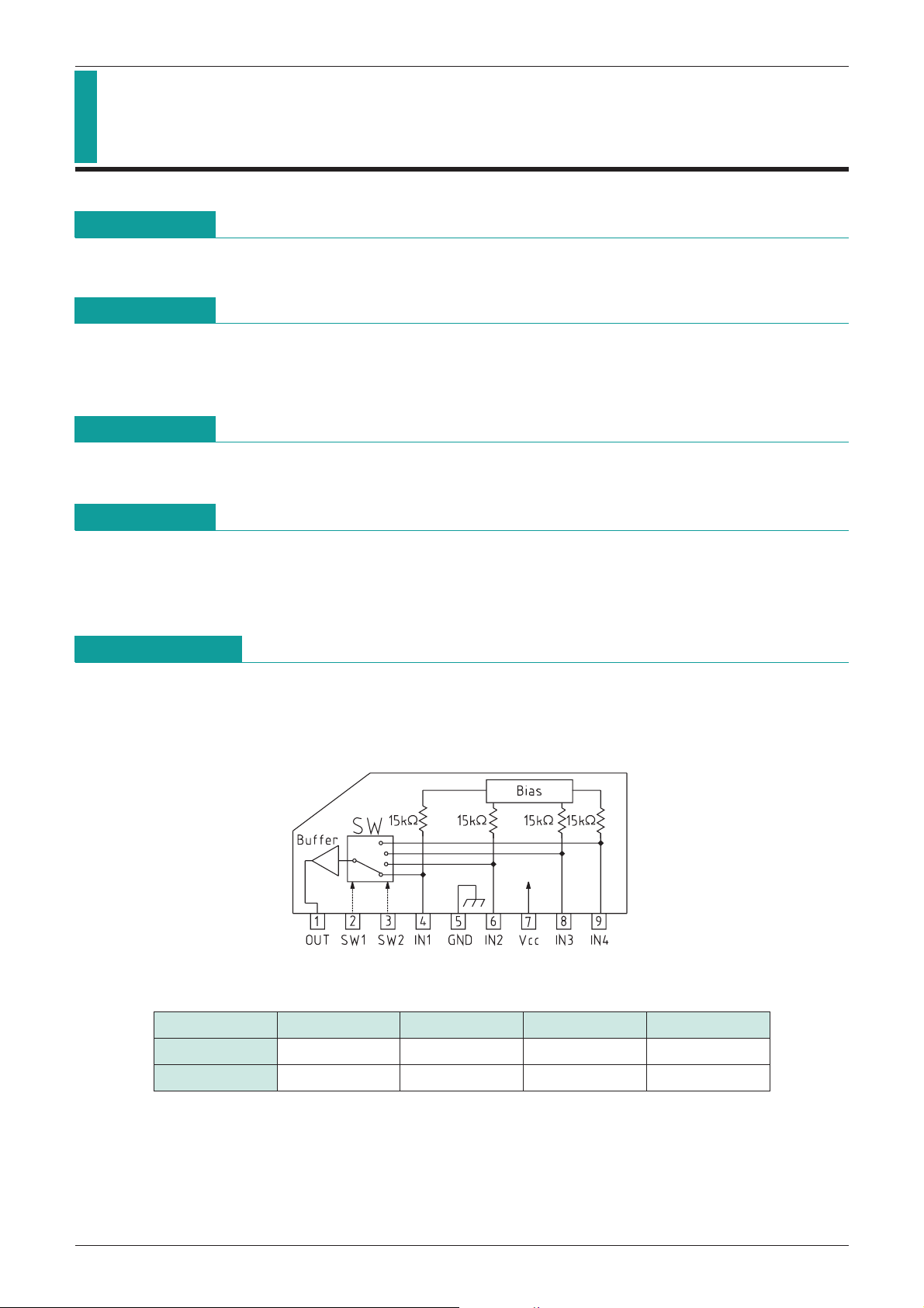
Block Diagram
Control input truth table
OUT IN1 IN2 IN3 IN4
SW1 HLHL
SW2 HH L L
Page 2
MITSUMI
4-Input Video Switch (no clamp) MM1053
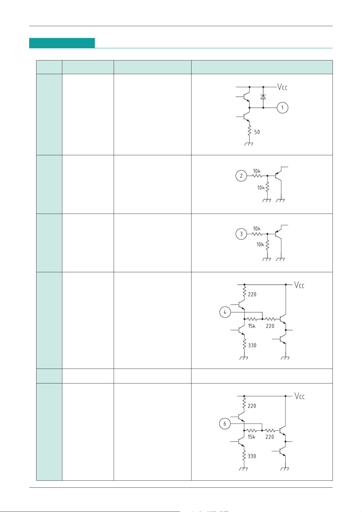
Pin Description
Pin no. Pin name Function Internal equivalent circuit diagram
1 OUT Output
2 SW1 Switch 1
3 SW2 Switch 2
4 IN1 Input 1
5 GND Ground
6 IN2 Input 2
Page 3

MITSUMI
7 VCC Power supply
8 IN3 Input 3
9 IN4 Input 4
4-Input Video Switch (no clamp) MM1053
Absolute Maximum Ratings
Item Symbol Ratings Units
Storage temperature T
Operating temperature T
Power supply voltage V
Allowable loss Pd 470 mW
(Ta=25°C)
STG
OPR
CC 15 V
-
40~+125 °C
-
20~+75 °C
Page 4

MITSUMI
4-Input Video Switch (no clamp) MM1053
Electrical Characteristics
(Except where noted otherwise, Ta=25°C, VCC=5.0V)
Measurement
Item Symbol
Measurement conditions Min. Typ. Max. Units
conditions
Operating power supply
V
CC VCC 4.75 5.0 13.0 V
voltage range
Consumption current Id V
Voltage gain G
Frequency characteristic F
V TP3
C TP
Differential gain DG TP3
Differential phase DP TP3
CC 7.0 11.0 mA
SG : Sine wave 2V
SG : Sine wave 2VP
3
10MHz/0.1MHz
SG : Staircase wave 2V
SG : Staircase wave 2V
P-P
, 0.1MHz *1
-
P
1
*
P-P
, APL=10, 50, 90%
P-P
, APL=10, 50, 90%
-
0.5 0 0.5 dB
-
10 1dB
03%
0 3 deg
Output offset voltage Voff TP2 100 mV
Crosstalk C
Switching voltage 1 V
Switching voltage 2 V
Input impedance R
Output impedance R
T TP3
TH1 TP4 SG : Sine wave 2VP-P, 0.1MHz
TH2 TP5 SG : Sine wave 2VP-P, 0.1MHz
I TP3 15 kΩ
O TP3 15 Ω
SG : Sine wave 2V
P-P
, 4.43MHz *2
-
65-55 dB
3 0.7 1.4 2.1 V
*
3 0.7 1.4 2.1 V
*
1 Voltage gain GV, frequency response FC
*
If input at TP1 for 0.1MHz sine wave input is V1, and output at TP3 is V2, and output for 10MHz
input is V3, then :
G
V=20LOG
C=20LOG
F
2 Crosstalk CT
*
If input at TP1 for 4.43MHz sine wave input is V4, and output at TP3 is V5, then :
C
T=20LOG
3 Switching voltage VTH1, VTH2
*
TP4 level is V
TH1 when TP4 DC level is changed by the external power supply and the output
signal switches. TP5 level is V
and the output signal switches.
V2
V1
V3
V2
V5
V4
TH2 when TP5 DC level is changed by the external power supply
Page 5

MITSUMI
Switch Modes
4-Input Video Switch (no clamp) MM1053
Item Symbol
S1 S2 S3 S4 S5 S6
Consumption current Id222233
122211
212231
Switch Mode
Voltage gain Gv
221213
222133
122211
212231
Frequency gain F
C
221213
222133
122211
212231
Differential gain DG
221213
222133
122211
212231
Differential phase DP
221213
222133
222211
222231
Output offset voltage Voff
222213
222233
212211
221211
222111
221231
222131
122231
Crosstalk C
T
222113
122213
212213
122233
212233
221233
V
Switching voltage
TH1122221
V
TH2122212
Page 6

MITSUMI
Measuring Circuit
4-Input Video Switch (no clamp) MM1053
 Loading...