

Page 1
www.fairchildsemi.com
ML4818
Phase Modulation/Soft Switching Controller
Features
• Full bridge phase modulation zero voltage switching
circuit with programmable ZV transition times
• Constant frequency operation to 500kHz
• Current mode operation
• Cycle-by-cycle current limiting with integrating fault
detection and restart delay
• Precision buffered 5V reference (+1%)
• Four 1.5A peak current totem-pole output drivers
• Under-voltage lockout circuit with 6V hysteresis
• Power DIP package
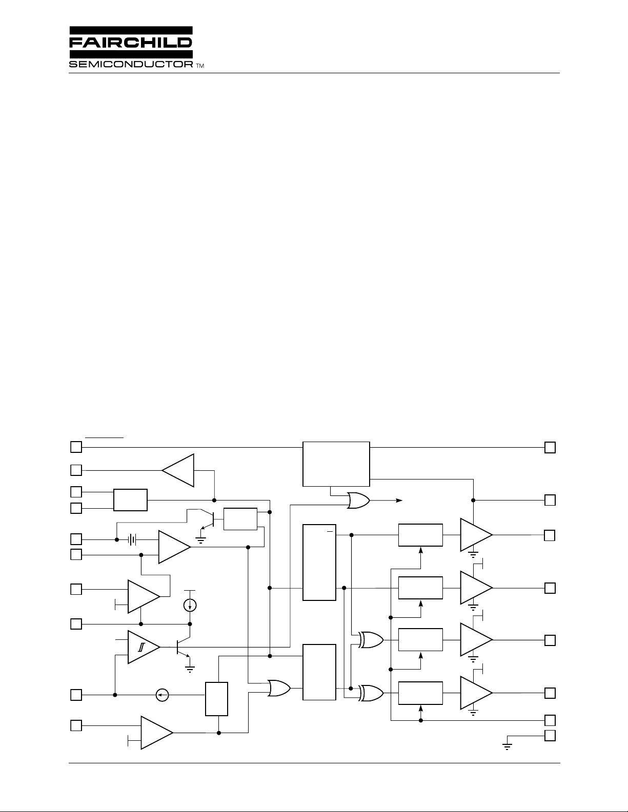
Block Diagram
SHUTDOWN
10
CLOCK
13
R
T
11
2
3
5
C
T
RAMP
E/A OUT
OSC
0.7V
R
Q
+
+
ΦMOD
–
S
General Description
The ML4818 is a complete phase modulation control IC suitable for full bridge soft switching converters. Unlik e conventional PWM circuits, the phase modulation technique allows
for zero-voltage switching transitions and square wave drive
across the transformer. The IC modulates the phases of the
two sides of the bridge to control output power.
The ML4818 can be operated in current mode. The delay
times for the outputs are externally programmable to allow
the zero-voltage switching transitions to take place.
Pulse-by-pulse current limit, integrating fault detection, and
soft start reset are provided. The under-voltage lockout circuit features a 6V hysteresis with a low starting current to
allow off-line start up with a low power bleed resistor. A
shutdown function powers down the IC, putting it into a low
quiescent state.
REFERENCE
AND
UNDER-VOLTAGE
LOCKOUT
INHIBIT
OUTPUTS
A2 OUT
CC
T FLIP
FLOP
DELAY
V
V
REF
24
V
CC
20
16
INV
8
SOFT START
9
12
I
LIM
4
+5V
RC
3V
RESET
1V
–
ERROR
AMP
+
–
+
+
–
V+
I
1
R
Q
I
2
S
TQQ
R
SQ
*PINS 1, 6, 7, 15, 18, 19 AND 23 ARE GND
DELAY
V
DELAY
V
DELAY
A1 OUT
17
CC
B1 OUT
22
CC
B2 OUT
21
R
DELAY
14
GND
*
REV. 1.0.3 6/21/01
Page 2
ML4818 PRODUCT SPECIFICATION
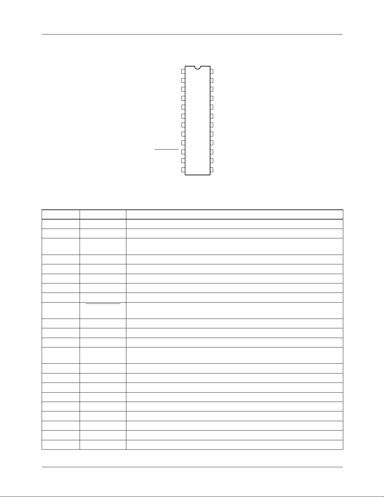
Pin Configuration
24-Pin Power DIP (P24)
V
GND
C
RAMP
I
LIM
E/A OUT
GND
GND
INV
SOFT START
SHUTDOWN
R
RC
RESET
T
T
24
1
23
2
22
3
21
4
20
5
19
6
18
7
17
8
16
9
15
10
14
11
13
12
TOP VIEW
REF
GND
B1 OUT
B2 OUT
V
CC
GND
GND
A1 OUT
A2 OUT
GND
R
DELAY
CLOCK
Pin Description
Pin Name Function
1 GND Ground
2CTTiming capacitor for oscillator
3 RAMP Non-inverting input to main comparator. Connected to current sense resistor for
current mode
4I
LIM
Current limit sense pin. Normally connected to current sense resistor
5 E/A OUT Output of error amplifier and input to PWM comparator
6,7 GND Ground and substrate
8 INV Inverting input to error amp
9 SOFT START Normally connected to soft start capacitor
10 SHUTDOWN Pulling this pin low puts the IC into a power down mode and turns off all outputs.
11 R
12 RC
T
RESET
This pin is internally pulled up to V
Resistor which sets discharge current for oscillator timing capacitor
Timing elements for Integrating fault detection and reset delay circuits
REF
.
13 CLOCK Oscillator output
14 R
DELAY
Resistor to ground on this pin programs the amount of delay from the time an
output turns off until its complementary output turns on
15 GND Ground
16 A2 OUT High current totem pole output A1
17 A1 OUT High current totem pole output A2
18,19 GND Ground and substrate
20 V
CC
Positive supply for the IC
21 B2 OUT High current totem pole output B1
22 B1 OUT High current totem pole output B2
23 GND Ground
24 V
REF
Buffered output for the 5V voltage reference
2 REV. 1.0.3 6/21/01
Page 3

PRODUCT SPECIFICATION ML4818
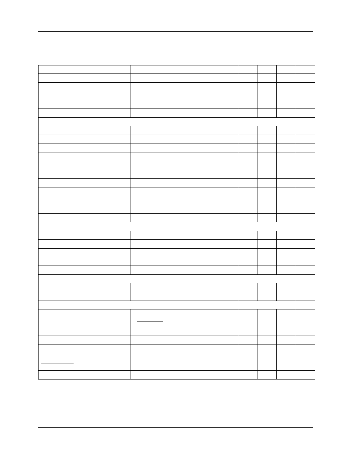
Absolute Maximum Ratings
Absolute Maximum Ratings are those values, beyond which the device could be permanently damaged. Absolute maximum
ratings are stress ratings only and functional device operation is not implied.
Parameter Min. Max. Units
V
CC
Output Driver Current, Source or Sink
DC
Pulse (0.5 µs)
Analog Inputs (CT, RAMP, I
RC
CLOCK Output Current (R
Error Amplifier Output Current (E/A OUT) 5 mA
SOFT START Sink Current 50 mA
Oscillator Charging Current (CT) –5mA
Junction Temperature 150 °C
Storage Temperature Range –65 150 °C
Lead Temperature (Soldering 10 Sec) 260 °C
Thermal Resistance (θJA)
Plastic Power DIP 40 °C/W
) –0.3 6 V
RESET
, E/A OUT, INV, SOFT START,
LIM
) –5mA
T
30 V
0.5
1.5
A
A
Operating Conditions
Parameter Min. Max. Units
Operating Temperature Range 0 70 °C
Electrical Characteristics
Unless otherwise specified, VCC = 15V, RT = 12.7kΩ, CT = 250pF, R
Temperature Range (Note 1).
Parameter Conditions Min. Typ. Max. Units
Oscillator
Initial Accuracy TA=25°C 410 450 525 kHz
Voltage Stability 12V<VCC<25V -0.3 %/V
Temperature Stability 0.2 %
Total Variation line, temp. 375 525 kHz
CT Discharge Current VCT=2V 4.7 5.5 6.3 mA
Clock Out High 2.4 3.1 6 V
Clock Out Low 0 0.4 V
Ramp Peak 0 4.1 V
Ramp Valley 1.5 5 V
Ramp Valley to Peak 0 2.6 5 V
Reference
Output Voltage TA=25°C, IO=1mA 4.95 5.0 5.05 V
Line Regulation 12V<VCC<25V -20 2 20 mV
Load Regulation 1mA<IO<10mA -20 3 20 mV
CLK
= 3kΩ, R
= 5kΩ, TA = Operating
DELAY
REV. 1.0.3 6/21/01 3
Page 4
ML4818 PRODUCT SPECIFICATION
Electrical Characteristics (continued)
Unless otherwise specified, VCC = 15V, RT = 12.7kΩ, CT = 250pF, R
Temperature Range (Note 1).
Parameter Conditions Min. Typ. Max. Units
Temperature Stability 0.2 mV/°C
Total Variation 4.85 5.15 V
Output Noise Voltage 10Hz to 10kHz 50 mV
Long Term Stability T
Short Circuit Current V
=125°C, 1000 hrs 5 25 mV
j
=0V -20 -50 mA
REF
Error Amplifier
Input Offset Voltage -40 30 mV
Input Bias Current -3 0.6 3 µA
Input Offset Current 0.1 1 µA
Open Loop Gain 1 < V
PSRR 12 < V
Output Sink Current V
Output Source Current V
Output High Voltage I
Output Low Voltage I
< 4V 70 75 dB
O
< 25V 65 80 dB
CC
EA OUT
EA OUT
EA OUT
EA OUT
= 1V 1 3.2 mA
= 5.1V –0.5 –2.2 –20 mA
= –0.5mA 5.0 5.5 6.0 V
= 1mA 0.8 V
Unity Gain Bandwidth 2.0 2.8 MHz
Slew Rate 8.5 V/µs
Phase Modulator
RAMP Bias Current V
EA OUT Zero DC Threshold V
= 2.5V –1 –10 µA
RAMP
= 0V 0.4 0.6 0.9 V
RAMP
tPD, RAMP to Output 50 80 ns
t
DELAY
R
DELAY Voltage
CL = 1nF 99 200 250 ns
Soft Start
Charge Current V
Discharge Current V
SOFT START
SOFT START
= 4V –15 –25 –30 µA
= 1V 10 20 30 mA
Current Limit/Shutdown
I
Bias Current 0V < V
LIM
Current Limit Threshold V
tPD, I
LIM
RC
RC
RC
Shutdown Threshold 3.15 3.4 3.65 V
RESET
Restart Threshold 1.0 1.3 1.6 V
RESET
Charging Current V
RESET
SHUTDOWN
ILIM
< 4V –10 –110µA
ILIM
= 0V 0.92 1.02 1.12 V
=2V, V
RCRESET
SHUTDOWN Threshold 2.0 2.4 2.8 V
SHUTDOWN Input Bias Current V
SHUTDOWN
= 0 –100 –25 10 µA
CLK
= 3kΩ, R
= 5kΩ, TA = Operating
DELAY
4 4.3 5V V
50 ns
= 1.5V –400 –523 –1000 µA
4 REV. 1.0.3 6/21/01
Page 5

ML4818 PRODUCT SPECIFICATION
Electrical Characteristics (continued)
Unless otherwise specified, V
= 15V, RT = 12.7kΩ, CT = 250pF, R
CC
Temperature Range (Note 1).
Parameter Conditions Min. Typ. Max. Units
Output
Output Low Level I
Output High Level I
= 20mA
OUT
= 200mA, TA = 25°C
I
OUT
= –20mA
OUT
= –200mA, TA = 25°C
I
OUT
Rise/Fall Time CL = 1000pF 50 75 ns
Under-Voltage Lockout
Start Threshold 15.5 16.5 17.2 V
Stop Threshold 9.25 10.2 10.7 V
Supply
Start Up Current VCC<15.8V 3 4 mA
I
CC
V
INV
= 4V, V
RAMP
= V
TA = 25°C (Note 2) 60 70 mA
Notes
1. Limits are guaranteed by 100% testing, sampling, or correlation with worst-case test conditions.
2. V
must be brought above the UVLO start voltage (17.2V) before dropping to VCC = 15V to ensure start-up.
CC
= 3kΩ, R
CLK
= 0V, CL = 1nF,
ILIM
= 5kΩ, TA = Operating
DELAY
12.0
11.0
0.1
0.7
13.5
13.0
0.4
2.8
V
V
V
V
5 REV. 1.0.3 6/21/01
Page 6

PRODUCT SPECIFICATION ML4818
Functional Description
Phase Modulator
Power is controlled by modulating the switching phase on
sides A and B of the full H-bridge converter (Figure 1).
Power is delivered to the output through the transformer secondary. The power conversion process is described by the
following sequence and illustrated by the timing diagram of
Figure 2:
1. A2 and B1 are high (Q1 and Q2 are on), beginning the
power conversion cycle.
2. After the Φ MOD comparator trips, B1 goes low turning
off Q2. The parasitic drain-to-source capacitances of Q2
and Q4 charge to +VIN. This forces the drain-to-source
voltage across Q3 to 0V.
T
A2
ML4818
A1
B2
B1
B
B
3. B2 now goes high after t
DELAY
(set by R
DELAY
). Since the
voltage across Q3 is now 0V, B2 turns Q3 on at zero
voltage.
4. The CLOCK now goes high turning A2 off. During this
period, Q1 and Q2 and Q4 are off. The transformer leakage current discharges the drain-to-source capacitance
on Q4 until there is 0V across it.
5. A1 will remain low for a period defined by t
DELAY
, then it
goes high. The voltage across Q4 is now 0V as A1 turns
it on at zero voltage.
6. The previous sequence is now repeated with the opposite polarity on all outputs (see Figure 2).
The above sequence is then repeated but with the opposite
polarity on all outputs.
+VIN
Q3
L
LEAKAGE
TRANSFORMER
Q2 Q4
Q1
A
T
A
I
LIM
R
SENSE
Figure 1. Simplified diagram of Phase Modulated power Outputs
C
T
CLOCK
A2
t
DELAY
A1
t
B1
B2
DELAY
t
PD1
t
DELAY
t
PD1
t
DELAY
B
A
t
PD1
t
DELAY
t
DELAY
Figure 2. Phase Modulation control waveforms (Shaded areas indicate a power cycle)
REV. 1.0.3 6/21/01 6
Page 7

ML4818 PRODUCT SPECIFICATION
The ML4818 can also be used in current mode by sensing
load current on the RAMP input (pin 3).
The four output delay timers are programmed via an external
R
resistor as shown below. This resistor value should be
DELAY
no less than 1kΩ. Expressing R
in kΩ the delay, in ns
DELAY
is:
T
DELAY
33 R
×〈〉= 45+
DELAY
(1)
I
SET
R
11
T
1.7V
2
C
T
5.5mA
Q1
I
SET
5V
5V
+
–
The ML4818 contains special logic circuits to provide for
voltage mode feed-forward and lock out long pulses into the
Figure 5. Ocillator Block Diagram
internal logic. This prevents instability from occuring when
the Φ Comparator trips in voltage mode.
For frequencies of less than 500kHz, oscillator frequency
can be set by using the following formulae:
Φ MOD
OUTPUT
OSC
S
Q
R
RAMP
Q
R
3
f
OSC
-------------------------------------------------- -=
0.52C
TRT
1
500C
+
T
Error Amplifier
Figure 3. Voltage Feed-Forward Circuit
The collector of QR in figure 3 is high only during a power
cycle. When the power cycle terminates, RAMP is pulled
low. In voltage mode operation, a capacitor is connected
from RAMP to GND with a resistor from RAMP to VIN to
provide input voltage feed forward.
Oscillator
The ML4818 oscillator charges the external capacitor, CT,
with a current (I
reaches the upper threshold (Ramp Peak), the comparator
changes state, turning on the current sink which discharges
CT to the lower threshold (Ramp Valley). The CT pin is
clamped to Ramp Valley by Q1 (Figure 5) to prevent inaccuracy due to undershoot on CT.
) equal to 5/RT. When the CT voltage
SET
The ML4818 error amplifier is a 2.5MHz bandwidth, 8.5V/
µs slew rate op-amp with provision for limiting the positive
output voltage swing (output inhibit line) to implement the
soft start function. The error amplifier output source current
is limited to 4.5mA.
120
100
80
60
GAIN
40
20
0
0 100 1k 10k 100k 1M 10M
GAIN
PHASE
FREQUENCY
CLOCK
OUT
250Ω
13
(2)
180
PHASE (Degrees)
135
90
45
0
To use the CLOCK output for driving external synchronization circuitry, a pull-down resistor is required from CLOCK
to GND.
CLOCK
RAMP PEAK
C
T
RAMP VALLEY
T
C
T
D
Figure 4. Ocillator Timing Diagram
Figure 6. Error Amplifier Open-Loop Gain and Phase vs.
Frequency
V
CC
V
Q2
Q1
CC
OUT
POWER
GND
Figure 7. Power Driver Simplified Schematic
7 REV. 1.0.3 6/21/01
Page 8

ML4818 PRODUCT SPECIFICATION
Output Driver Stage
7
6
5
4
3
2
SATURATION DROP (V)
1
0
0 0.2 0.4 0.6 0.8 1.0 1.2 1.4
SOURCE
SINK
OUTPUT CURRENT (A)
Figure 8. Output Drive Saturation Voltage vs.
Output Current
15
The ML4818 has four high current high speed totem pole
output drivers each capable of 1.5A peak output, designed to
quickly switch the gates of capacitive loads, such as power
MOSFET transistors. Figure 8 illustrates the saturation characteristics of the ouput drive transistors shown in Figure 7.
Typical rise and fall time characteristics of the output drivers
are illustrated with capacitive loads of 1nF and 10nF in
Figure 9.
Current Limit, Fault Detection and Soft Start
Current limit is implemented when the current sensed on I
reaches the 1V limit. At this point, the PWM cycle is terminated. The flip flop (Figure 10) turns on the current source to
charge C
period. When C
and remains on for the duration of the clock
RST
has charged to 3.4V, a soft start reset
RST
occurs. The number of times the PWM cycle is terminated
due to over-current is “remembered” on C
C
is discharged by R
RST
providing a measure of “forget-
RST
. Over time,
RST
ting” when the over-current condition no longer occurs. This
integrating fault detection is useful in differentiation between
short circuit and load surge conditions.
LIM
10
1nF
5
OUTPUT VOLTAGE (V)
10nF
1nF
~
~
100 200 100 200
t
F
(ns)
t
R
10nF
Figure 9. Output Rise/Fall Time
V+
I
SWITCH
R
SENSE
R1
SOFT START
9
C
SS
I
LIM
4
C1
V+
1V
+
–
I
1
TERMINATE
PWM CYCLE
S
Q
I2
12
RC
R
RST
C
RST
RESET
3.4V
1.3V
R
CLOCK
+
–
UNDER-VOLTAGE
INHIBIT
OUTPUT
LOCKOUT
Figure 10. Over-Current, Soft-Start, and Integrating Fault Detect Circuits
8 REV. 1.0.3 6/21/01
Page 9

PRODUCT SPECIFICATION ML4818
V
Since the per cycle charge on RC
is proportional to how
RESET
early in the power cycle the over-current occurs, a reset will
occur more quickly under output short circuit conditions
(Figures 11a and 11b) than during a load surge (Figures 11c
and 11d).
When the soft start reset occurs, the output is inhibited and
the soft start capacitor is discharged. The output will remain
off until C
discharges to 1.3V through R
RST
, providing a
RST
reset delay. When the IC restarts, the error amplifier output
voltage is limited to the voltage at SOFT START, thus limiting the duty cycle.
1V
V(PIN 4)
3.4V
V(PIN 12)
Figure 11a, 11b. I
Waveforms During Short Circuit
and Resulting RC
LIMIT
RESET
Under-Voltage Lockout
On power up, when VCC is below 16V, the IC draws very little current (1.1mA typ.) and V
above 16V, the IC becomes active and V
will stay in that condition until V
Figure 12).
INHIBIT
OUTPUTS
POWER
DOWN
+
–
Figure 12. Under-Voltage Lockout and Reference Circuits
is disabled. When VCC rises
REF
falls below 10.2V. (see
CC
9V
REF
–
+
INTERNAL
BIAS
is enabled and
4V
TO LOGIC
CIRCUITS
5V
V
V
REF
24
CC
20
1V
V(PIN 4)
3.4V
(PIN 12)
Figure 11c, 11d. I
and Resulting RC
Waveforms During Load Surge
LIMIT
RESET
70
68
66
64
62
60
58
56
SUPPLY CURRENT (mA)
54
52
50
–75 –25 25 75 125 175
TEMPERATURE
Figure 13. Supply Current vs. Temperature (°C)
REV. 1.0.3 6/21/01 9
Page 10

ML4818 PRODUCT SPECIFICATION
Thermal Information
The ML4818 is offered in a Power DIP package. This package features improved thermal conduction through the leadframe. Much of the heat is conducted through the center 4
grounded leads. Thermal dissipation can be improved with
this package by using copper area on the board to function as
a heat sink. Increasing this area can reduce the θ
ures 14 and 15), increasing the power handling capability of
the package. Additional impro vement may be obtained by
using an external heat sink (available from Staver).
0.555"
24
1
23
2
22
3
21
4
20
5
19
I
I
Figure 14. PC Board Copper Area Used as a Heat Sink
6
18
7
17
8
16
9
15
10
14
11
13
12
JA
I
(see fig-
Applications
The application circuit shown in Figure 16 features the
ML4818 in a primary-side controlled voltage mode
application with voltage feed-forward. Input voltage is
rectified 120VAC (nominal). Feed-forward is provided by
the RAMP pin via the resistor connected to the high voltage
input. Current is sensed through sense transformer T4.
50
40
I
30
20
0.2 0.4 0.6 0.8 1 1.2 1.4 1.6 1.8
02
I : HEAT SINK DIMENSION (INCHES)
Figure 15. θ
as a Function of I (see figure 15)
JA
10 REV. 1.0.3 6/21/01
Page 11

PRODUCT SPECIFICATION ML4818
,
–
+
OUT
15V, 13A
V
4 x 1N5406,
+HV
82kΩ, 1W
5A, 250V
3A, 600V
1/4W
240kΩ
+
200V
680µF,
MUR150
200µH
CC
V
AC IN
FUSE
+
T1
4T
+
100µF
1/4W
240kΩ
200V
680µF,
4T
MUR150
25V
1µF
120VAC–220VAC JUMPER
J1
T3
IRF840B
0.01µF
IRF840B
5.1Ω, 1/4W 5.1Ω, 1/4W
T2
1µF
1kV
1N5818
10T 10T
10T
10T
2 x IN5248
SCHOTTKY
MBR1535CT
T1
45T
80T
T4
39Ω
2 x IN5248
15µH
DIODE
0.33µF
1T
1/4W
1N5818
1µF
+
25V
100µF
4T 4T
630V
1N4148
1N5818
IC2
CC
V
1kΩ,1/4W
5.1Ω, 1/4W
5.1Ω, 1/4W
T2
MOC8102
1kΩ
T3
10T
IRF840B
IRF840B
10T
POT
1N5818
510
1/4W
1µF
330kΩ
1/4W
0.1µF
2423222120191817161514
ML4818
1234567891011
470pF
680pF
100kΩ
220pF
120pF
5.1kΩ 1/4W
1000pF
470pF
7.5kΩ, 1/4W
13
12
1µF
100kΩ
1/4W
4.3kΩ, 1/4W
1µF
240kΩ, 1/4W
Figure 16. Offline Full Bridge Converter
REV. 1.0.3 6/21/01 11
Page 12

ML4818 PRODUCT SPECIFICATION
Mechanical Dimensions inches (millimeters)
Package: P24N
24-Pin Narrow PDIP
1.240 - 1.260
(31.49 - 32.01)
24
0.070 MIN
(1.77 MIN)
(4 PLACES)
0.170 MAX
(4.32 MAX)
0.125 MIN
(3.18 MIN)
PIN 1 ID
1
0.050 - 0.065
(1.27 - 1.65)
0.016 - 0.022
(0.40 - 0.56)
0.240 - 0.270
(6.09 - 6.86)
0.100 BSC
(2.54 BSC)
0.015 MIN
(0.38 MIN)
SEATING PLANE
0.295 - 0.325
(7.49 - 8.26)
0º - 15º
0.008 - 0.012
(0.20 - 0.31)
12 REV. 1.0.3 6/21/01
Page 13

ML4818 PRODUCT SPECIFICATION
Ordering Information
Part Number Temperature Range Package
ML4818CP 0°C to 70°C Power DIP (P24)
DISCLAIMER
FAIRCHILD SEMICONDUCTOR RESERVES THE RIGHT TO MAKE CHANGES WITHOUT FURTHER NOTICE TO
ANY PRODUCTS HEREIN TO IMPROVE RELIABILITY, FUNCTION OR DESIGN. FAIRCHILD DOES NOT ASSUME
ANY LIABILITY ARISING OUT OF THE APPLICATION OR USE OF ANY PRODUCT OR CIRCUIT DESCRIBED HEREIN;
NEITHER DOES IT CONVEY ANY LICENSE UNDER ITS PATENT RIGHTS, NOR THE RIGHTS OF OTHERS.
LIFE SUPPORT POLICY
FAIRCHILD’S PRODUCTS ARE NOT AUTHORIZED FOR USE AS CRITICAL COMPONENTS IN LIFE SUPPORT DEVICES
OR SYSTEMS WITHOUT THE EXPRESS WRITTEN APPROVAL OF THE PRESIDENT OF FAIRCHILD SEMICONDUCTOR
CORPORATION. As used herein:
1. Life support devices or systems are devices or systems
which, (a) are intended for surgical implant into the body,
or (b) support or sustain life, and (c) whose failure to
perform when properly used in accordance with
2. A critical component in any component of a life support
device or system whose failure to perform can be
reasonably expected to cause the failure of the life support
device or system, or to affect its safety or effectiveness.
instructions for use provided in the labeling, can be
reasonably expected to result in a significant injury of the
user.
www.fairchildsemi.com
6/21/01 0.0m 003
© 2001 Fairchild Semiconductor Corporation
Stock#DS30004841
 Loading...