

Page 1
LM185-1.2/LM285-1.2/LM385-1.2
Micropower Voltage Reference Diode
General Description
The LM185-1.2/LM285-1.2/LM385-1.2 are micropower 2-terminal band-gap voltage regulator diodes. Operating over a
10μA to 20mA current range, they feature exceptionally low
dynamic impedance and good temperature stability. On-chip
trimming is used to provide tight voltage tolerance. Since the
LM185-1.2 band-gap reference uses only transistors and resistors, low noise and good long term stability result.
Careful design of the LM185-1.2 has made the device exceptionally tolerant of capacitive loading, making it easy to use in
almost any reference application. The wide dynamic operating range allows its use with widely varying supplies with
excellent regulation.
The extremely low power drain of the LM185-1.2 makes it
useful for micropower circuitry. This voltage reference can be
used to make portable meters, regulators or general purpose
analog circuitry with battery life approaching shelf life.
Further, the wide operating current allows it to replace older
references with a tighter tolerance part.
The LM185-1.2 is rated for operation over a −55°C to 125°C
temperature range while the LM285-1.2 is rated −40°C to 85°
C and the LM385-1.2 0°C to 70°C. The LM185-1.2/LM285-1.2
are available in a hermetic TO-46 package and the
LM285-1.2/LM385-1.2 are also available in a low-cost TO-92
molded package, as well as SO and SOT-23. The LM185-1.2
is also available in a hermetic leadless chip carrier package.
Features
±1% and 2% initial tolerance
■
Operating current of 10μA to 20mA
■
1Ω dynamic impedance
■
Low temperature coefficient
■
Low voltage reference—1.235V
■
2.5V device and adjustable device also available
■
LM185-2.5 series and LM185 series, respectively
■
LM185-1.2/LM285-1.2/LM385-1.2 Micropower Voltage Reference Diode
January 30, 2008
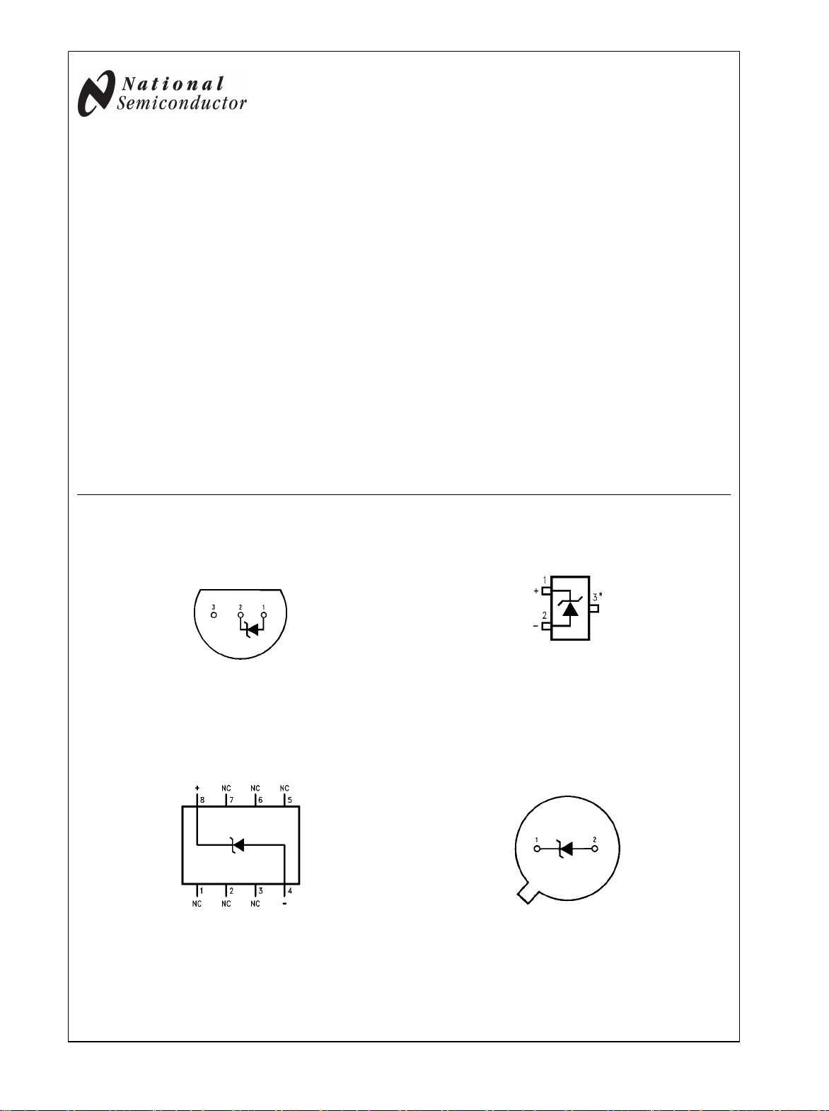
Connection Diagrams
T0-92
Plastic Package (Z)
Bottom View
Order Number LM285Z-1.2,
LM285BXZ-1.2, LM285BYZ-1.2
LM385Z-1.2, LM385BZ-1.2
LM385BXZ-1.2 or LM385BYZ-1.2
See NS Package Number Z03A
SO Package
Order Number LM285M-1.2,
LM285BXM-1.2, LM285BYM-1.2
LM385M-1.2, LM385BM-1.2
LM385BXM-1.2 or LM385BYM-1.2
See NS Package Number M08A
551810
551809
SOT23
* Pin 3 is attached to the Die Attach Pad (DAP) and should be connected to
Pin 2 or left floating.
Order Number LM385M3-1.2
See NS Package Number MF03A
Metal Can Package (H)
Bottom View
Order Number LM185H-1.2, LM185H-1.2/883,
LM185BXH-1.2, LM185BYH-1.2
LM285H-1.2 or LM285BXH-1.2
See NS Package Number H02A
551833
TO-46
551806
© 2008 National Semiconductor Corporation 5518 www.national.com
Page 2
Absolute Maximum Ratings (Note 1)
If Military/Aerospace specified devices are required,
please contact the National Semiconductor Sales Office/
Distributors for availability and specifications.
(Note 2)
Reverse Current 30mA
Forward Current 10mA
Operating Temperature Range (Note 3)
LM185-1.2 −55°C to +125°C
LM285-1.2 −40°C to +85°C
ESD Susceptibility (Note 9) 2kV
Storage Temperature −55°C to +150°C
Soldering Information
TO-92 package: 10 sec. 260°C
TO-46 package:10 sec. 300°C
SO and SOT Pkg.
Vapor phase (60 sec.) 215°C
Infrared (15 sec.) 220°C
See AN-450 “Surface Mounting Methods and Their Effect
on Product Reliability” for other methods of soldering
surface mount devices.
LM385-1.2 0°C to 70°C
Electrical Characteristics (Note 4)
LM185-1.2/LM285-1.2/LM385-1.2
LM185-1.2
LM185BX-1.2 LM385B-1.2
LM185BY-1.2 LM385BX-1.2 LM385-1.2
LM285-1.2 LM385BY-1.2 Units
Parameter Conditions Typ LM285BX-1.2 (Limit)
LM285BY-1.2
Tested Design Tested Design Tested Design
Limit Limit Limit Limit Limit Limit
(Notes 5,8)(Note 6) (Note 5) (Note 6) (Note 5) (Note 6)
Reverse Breakdown TA = 25°C, 1.2351.223 1.223 1.205 V(Min)
Voltage
10μA ≤ IR ≤ 20mA
Minimum Operating 8 10 20 15 20 15 20
Current
Reverse Breakdown
LM385M3-1.2 10 15
10μA ≤ IR ≤ 1mA
1.247 1.247 1.260 V(Max)
μA
(Max)
1 1.5 1 1.5 1 1.5 mV
Voltage Change (Max)
with Current
1mA ≤ IR ≤ 20mA
10 20 20 25 20 25 mV
(Max)
Reverse Dynamic
IR = 100μA, f = 20Hz
1
Ω
Impedance
Wideband Noise
(rms)
Long Term Stability
IR = 100μA,
10Hz ≤ f ≤ 10kHz
IR = 100μA, T = 1000 Hr,
60
20
μV
ppm
TA = 25°C ±0.1°C
Average Temperature
IR = 100μA
Coefficient (Note 7) X Suffix 30 30 ppm/°C
Y Suffix 50 50 ppm/°C
All Others 150 150 150 ppm/°C
(Max)
Note 1: Absolute Maximum Ratings indicate limits beyond which damage to the device may occur. Operating Ratings indicate conditions for which the device
is intended to be functional, but do not guarantee specific performance limits. For guaranteed specifications and test conditions, see the Electrical Characteristics.
The guaranteed specifications apply only for the test conditions listed.
Note 2: Refer to RETS185H-1.2 for military specifications.
Note 3: For elevated temperature operation, Tj max is:
LM185 150°C
LM285 125°C
LM385 100°C
www.national.com 2
Page 3
Thermal Resistance TO-92 TO-46 SO-8 SOT23
θJA (junction to ambient)
180°C/W (0.4″ leads) 440°C/W 165°C/W 283°C/W
170°C/W (0.125″ leads)
θJC (junction to case)
Note 4: Parameters identified with boldface type apply at temperature extremes. All other numbers apply at TA = TJ = 25°C.
Note 5: Guaranteed and 100% production tested.
Note 6: Guaranteed, but not 100% production tested. These limits are not used to calculate average outgoing quality levels.
Note 7: The average temperature coefficient is defined as the maximum deviation of reference voltage at all measured temperatures between the operating
T
and T
MAX
Note 8: A military RETS electrical specification is available on request.
Note 9: The human body model is a 100 pF capacitor discharged through a 1.5 kΩ resistor into each pin.
, divided by T
MIN
MAX
− T
. The measured temperatures are −55°C, −40°C, 0°C, 25°C, 70°C, 85°C, 125°C.
MIN
N/A 80°C/W N/A N/A
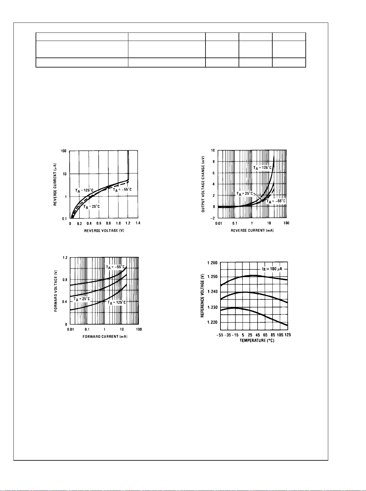
Typical Performance Characteristics
LM185-1.2/LM285-1.2/LM385-1.2
Reverse Characteristics
Forward Characteristics
551813
Reverse Characteristics
551814
Temperature Drift of 3
Representative Units
551815
551816
3 www.national.com
Page 4

Reverse Dynamic Impedance
LM185-1.2/LM285-1.2/LM385-1.2
551817
Reverse Dynamic Impedance
551818
Noise Voltage
Response Time
551819
Filtered Output Noise
551820
551821
Typical Applications
Wide Input
Range Reference
551808
www.national.com 4
Micropower Reference
from 9V Battery
551822
Reference from
Page 5

1.5V Battery
551823
Micropower* 5V Regulator
LM185-1.2/LM285-1.2/LM385-1.2
*IQ ≃20μA standby current
Precision 1μA to 1mA Current Sources
551826
*IQ ≃ 30μA
Micropower* 10V Reference
551825
551824
551827
5 www.national.com
Page 6

METER THERMOMETERS
0°C−100°C Thermometer
†IQ at 1.3V″500μA
IQ at 1.6V″2.4mA
Lower Power Thermometer
LM185-1.2/LM285-1.2/LM385-1.2
Calibration
1. Short LM385-1.2, adjust R3 for I
2. Remove short, adjust R2 for correct reading in centigrade
= temp at 1μA/°K
OUT
0°F−50°F Thermometer
Calibration
1. Short LM385-1.2, adjust R3 for I
2. Remove short, adjust R2 for correct reading in °F
= temp at 1.8μA/°K
OUT
Micropower Thermocouple Cold Junction Compensator
551828
551830
*2N3638 or 2N2907 select for inverse HFE ″ 5
†Select for operation at 1.3V
‡IQ ≃ 600μA to 900μA
Adjustment Procedure
1. Adjust TC ADJ pot until voltage across R1 equals Kelvin temperature
multiplied by the thermocouple Seebeck coefficient.
2. Adjust zero ADJ pot until voltage across R2 equals the thermocouple
Seebeck coefficient multiplied by 273.2.
551829
ThermocoupleSeebeck R1 R2 Voltage Voltage
Type Coefficient
(Ω) (Ω)
AcrossR1Across
R2
(μV/°C)
@ 25°C (mV)
(mV)
J 52.3 5231.24k15.60 14.32
T 42.8 4321k 12.77 11.78
K 40.8 41
2
S 6.4 63.
4
12.17 11.17
95
3Ω
1.908 1.766
15
0Ω
Typical supply current 50μA
551831
www.national.com 6
Page 7

Centigrade Thermometer
LM185-1.2/LM285-1.2/LM385-1.2
Calibration
1. Adjust R1 so that V1 = temp at 1mV/°K
2. Adjust V2 to 273.2mV
†IQ for 1.3V to 1.6V battery voltage = 50μA to 150μA
Schematic Diagram
551801
551807
7 www.national.com
Page 8

Physical Dimensions inches (millimeters) unless otherwise noted
LM185-1.2/LM285-1.2/LM385-1.2
Order Number LM185H-1.2, LM185H-1.2/883, LM185BXH-1.2, LM185BYH-1.2, LM285H-1.2, or LM285BXH-1.2
TO-46 Metal Can Package (H)
NS Package Number H02A
SOT-23 Package (M3)
Order Number LM385M3-1.2
NS Package Number MF03A
www.national.com 8
Page 9

LM185-1.2/LM285-1.2/LM385-1.2
Order Number LM285M-1.2, LM285BXM-1.2, LM285BYM-1.2
LM385M-1.2, LM385BM-1.2, LM385BXM-1.2, LM385BYM-1.2
Small Outline (SO-8) Package
NS Package Number M08A
Order Number LM285Z-1.2, LM285BXZ-1.2
LM285BYZ-1.2, LM385Z-1.2, LM385BZ-1.2
TO-92 Plastic Package (Z)
LM385BXZ-1.2 or LM385BYZ-1.2
NS Package Number Z03A
9 www.national.com
Page 10

Notes
For more National Semiconductor product information and proven design tools, visit the following Web sites at:
Products Design Support
Amplifiers www.national.com/amplifiers WEBENCH www.national.com/webench
Audio www.national.com/audio Analog University www.national.com/AU
Clock Conditioners www.national.com/timing App Notes www.national.com/appnotes
Data Converters www.national.com/adc Distributors www.national.com/contacts
Displays www.national.com/displays Green Compliance www.national.com/quality/green
Ethernet www.national.com/ethernet Packaging www.national.com/packaging
Interface www.national.com/interface Quality and Reliability www.national.com/quality
LVDS www.national.com/lvds Reference Designs www.national.com/refdesigns
Power Management www.national.com/power Feedback www.national.com/feedback
Switching Regulators www.national.com/switchers
LDOs www.national.com/ldo
LED Lighting www.national.com/led
PowerWise www.national.com/powerwise
Serial Digital Interface (SDI) www.national.com/sdi
Temperature Sensors www.national.com/tempsensors
Wireless (PLL/VCO) www.national.com/wireless
THE CONTENTS OF THIS DOCUMENT ARE PROVIDED IN CONNECTION WITH NATIONAL SEMICONDUCTOR CORPORATION
(“NATIONAL”) PRODUCTS. NATIONAL MAKES NO REPRESENTATIONS OR WARRANTIES WITH RESPECT TO THE ACCURACY
OR COMPLETENESS OF THE CONTENTS OF THIS PUBLICATION AND RESERVES THE RIGHT TO MAKE CHANGES TO
SPECIFICATIONS AND PRODUCT DESCRIPTIONS AT ANY TIME WITHOUT NOTICE. NO LICENSE, WHETHER EXPRESS,
IMPLIED, ARISING BY ESTOPPEL OR OTHERWISE, TO ANY INTELLECTUAL PROPERTY RIGHTS IS GRANTED BY THIS
DOCUMENT.
TESTING AND OTHER QUALITY CONTROLS ARE USED TO THE EXTENT NATIONAL DEEMS NECESSARY TO SUPPORT
NATIONAL’S PRODUCT WARRANTY. EXCEPT WHERE MANDATED BY GOVERNMENT REQUIREMENTS, TESTING OF ALL
PARAMETERS OF EACH PRODUCT IS NOT NECESSARILY PERFORMED. NATIONAL ASSUMES NO LIABILITY FOR
APPLICATIONS ASSISTANCE OR BUYER PRODUCT DESIGN. BUYERS ARE RESPONSIBLE FOR THEIR PRODUCTS AND
APPLICATIONS USING NATIONAL COMPONENTS. PRIOR TO USING OR DISTRIBUTING ANY PRODUCTS THAT INCLUDE
NATIONAL COMPONENTS, BUYERS SHOULD PROVIDE ADEQUATE DESIGN, TESTING AND OPERATING SAFEGUARDS.
EXCEPT AS PROVIDED IN NATIONAL’S TERMS AND CONDITIONS OF SALE FOR SUCH PRODUCTS, NATIONAL ASSUMES NO
LIABILITY WHATSOEVER, AND NATIONAL DISCLAIMS ANY EXPRESS OR IMPLIED WARRANTY RELATING TO THE SALE
AND/OR USE OF NATIONAL PRODUCTS INCLUDING LIABILITY OR WARRANTIES RELATING TO FITNESS FOR A PARTICULAR
PURPOSE, MERCHANTABILITY, OR INFRINGEMENT OF ANY PATENT, COPYRIGHT OR OTHER INTELLECTUAL PROPERTY
RIGHT.
LIFE SUPPORT POLICY
LM185-1.2/LM285-1.2/LM385-1.2 Micropower Voltage Reference Diode
NATIONAL’S PRODUCTS ARE NOT AUTHORIZED FOR USE AS CRITICAL COMPONENTS IN LIFE SUPPORT DEVICES OR
SYSTEMS WITHOUT THE EXPRESS PRIOR WRITTEN APPROVAL OF THE CHIEF EXECUTIVE OFFICER AND GENERAL
COUNSEL OF NATIONAL SEMICONDUCTOR CORPORATION. As used herein:
Life support devices or systems are devices which (a) are intended for surgical implant into the body, or (b) support or sustain life and
whose failure to perform when properly used in accordance with instructions for use provided in the labeling can be reasonably expected
to result in a significant injury to the user. A critical component is any component in a life support device or system whose failure to perform
can be reasonably expected to cause the failure of the life support device or system or to affect its safety or effectiveness.
National Semiconductor and the National Semiconductor logo are registered trademarks of National Semiconductor Corporation. All other
brand or product names may be trademarks or registered trademarks of their respective holders.
Copyright© 2008 National Semiconductor Corporation
For the most current product information visit us at www.national.com
www.national.com
National Semiconductor
Americas Technical
Support Center
Email:
new.feedback@nsc.com
Tel: 1-800-272-9959
National Semiconductor Europe
Technical Support Center
Email: europe.support@nsc.com
German Tel: +49 (0) 180 5010 771
English Tel: +44 (0) 870 850 4288
National Semiconductor Asia
Pacific Technical Support Center
Email: ap.support@nsc.com
National Semiconductor Japan
Technical Support Center
Email: jpn.feedback@nsc.com
 Loading...