

Page 1
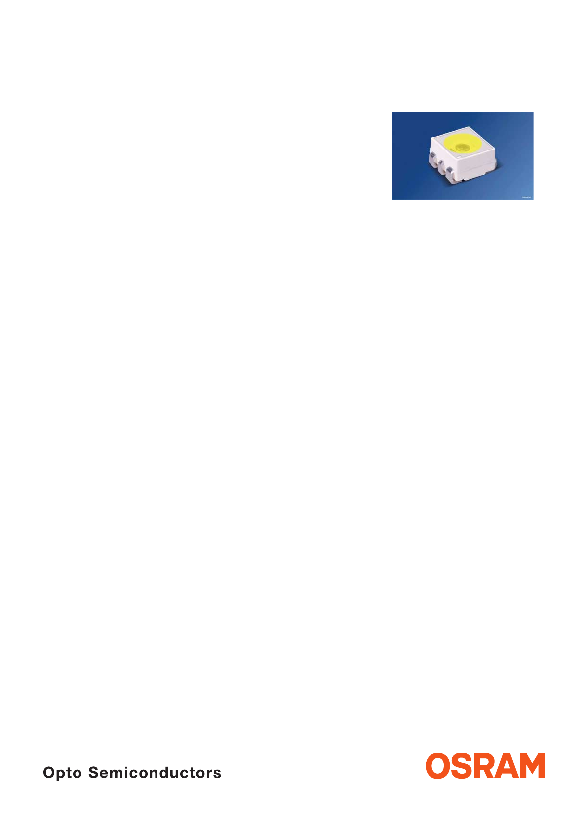
Advanced Power TOPLED
®
Enhanced optical Power LED (ThinGaN®)
Lead (Pb) Free Product - RoHS Compliant
LCW G6SP
Vorläufige Daten / Preliminary Data
Besondere Merkmale
• Gehäusetyp: weißes P-LCC-6 Gehäuse,
farbiger diffuser Silikon - Verguss
• Besonderheit des Bauteils: sehr kleiner
thermischer Widerstand, dadurch sehr hohe
Lichtleistung möglich
• Farbort: x = 0,42, y = 0,40 nach
CIE 1931 (weiß)
• typ. Farbtemperatur: 2700K; 3000K; 3500K;
4200K
• Abstrahlwinkel: Lambertscher Strahler (120°)
• Technologie:
• optischer Wirkungsgrad: 24 lm/W
• Gruppierungsparameter: Lichtstärke,
Farbort, Durchlassspannung
• Verarbeitungsmethode: für alle
SMT-Bestücktechniken geeignet
• Lötmethode: IR Reflow Löten
• Vorbehandlung: nach JEDEC Level 2
• Gurtung: 12 mm Gurt mit 1000/Rolle,
ø180 mm
• ESD-Festigkeit: ESD-sicher bis 2 kV nach
JESD22-A114-D
ThinGaN
®
Features
• package: white P-LCC-6 package, colored
diffused silicone resin
• feature of the device: very low thermal
resistance; high optical power
• color coordinates: x = 0.42, y = 0.40 acc. to
CIE 1931 (white)
• typical color temperature: 2700K; 3000K;
3500K; 4200K
• viewing angle: Lambertian Emitter (120°)
• technology:
• optical efficiency: 24 lm/W
• grouping parameter: luminous intensity,
color coordinates, forward voltage
• assembly methods: suitable for all
SMT assembly methods
• soldering methods: IR reflow soldering
• preconditioning: acc. to JEDEC Level 2
• taping: 12 mm tape with 1000/reel, ø180 mm
• ESD-withstand voltage: up to 2 kV acc. to
JESD22-A114-D
ThinGaN
®
Anwendungen
• Innenbeleuchtung im Automobilbereich (z.B.
Instrumentenbeleuchtung)
• Hinterleuchtung (Werbebeleuchtung,
Allgemeinbeleuchtung)
• Leselampen (Flugzeug, Auto, Bus)
• Ersatz von Kleinst-Glühlampen
• Display Hinterleuchtung mit hohem
Helligkeitsbedarf z. B. TFT
• Dekorative Beleuchtung
• Signal- und Symbolleuchten zur Orientierung
• Markierungsbeleuchtung (z.B. Stufen, Fluchtwege, u.ä.)
2007-08-09 1
Applications
• interior automotive lighting (e.g. dashboard
backlighting)
• backlighting (illuminated advertising, general
lighting)
• reading lamps (aircraft, car, bus)
• substitution of micro incandescent lamps
• display backlight where high brightness is
required e.g. TFT
• decorative and entertainment lighting
• signal and symbol luminaire for orientation
• marker lights (e.g. steps, exit ways, etc.)
Page 2
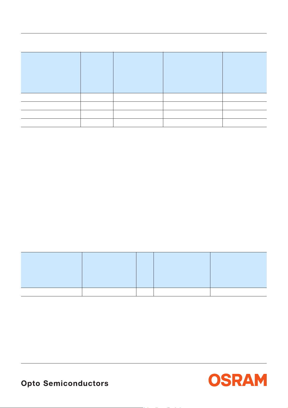
Bestellinformation
Ordering Information
Typ
Emissionsfarbe
Lichtstärke
1) Seite 18
Lichtstrom
2) Seite 18
LCW G6SP
Bestellnummer
Type
Color of
Emission
Luminous
Intensity
1) page 18
IF = 140 mA
I
(mcd)
V
Luminous Flux2)
IF = 140 mA
Φ
(mlm)
V
page 18
Ordering Code
LCW G6SP-CAEA-H3K5 warm white 2800 ... 9000 17700 (typ.) Q65110A5912
LCW G6SP-CAEA-L3M5 warm white 2800 ... 9000 17700 (typ.) Q65110A5913
LCW G6SP-BBEA-N3P5 warm white 2240 ... 9000 16800 (typ.) Q65110A5914
LCW G6SP-BBEA-Q3R5 warm white 2240 ... 9000 16800 (typ.) Q65110A5915
Anm.: Die oben genannten Typbezeichnungen umfassen die bestellbaren Selektionen. Diese bestehen aus wenigen
Helligkeitsgruppen (siehe Seite 7 für nähere Informationen). Es wird nur eine einzige Helligkeitsgruppe pro Gurt
geliefert. Z.B.: LCW G6SP-CAEA-H3K5-1 bedeutet, dass auf dem Gurt nur eine der Helligkeitsgruppen CA, CB, DA,
DB oder EA enthalten ist.
Um die Liefersicherheit zu gewährleisten, können einzelne Helligkeitsgruppen nicht bestellt werden.
Gleiches gilt für die Farben, bei denen Farbortgruppen gemessen und gruppiert werden. Pro Gurt wird nur eine
Farbortgruppe geliefert. Z.B.: LCW G6SP-CAEA-H3K5-1 bedeutet, dass auf dem Gurt nur eine der Farbortgruppen
-H3, -H4, H5, J3, J4, J5, K3, K4 oder -K5 enthalten ist (siehe Seite 5 für nähere Information).
Um die Liefersicherheit zu gewährleisten, können einzelne Farbortgruppen nicht bestellt werden.
Note: The above Type Numbers represent the order groups which include only a few brightness groups (see page 7 for
explanation). Only one group will be shipped on each reel (there will be no mixing of two groups on each reel). E.g.
LCW G6SP-CAEA-H3K5-1 means that only one group CA, CB, DA, DB or EA will be shippable for any one reel.
In order to ensure availability, single brightness groups will not be orderable.
In a similar manner for colors where chromaticity coordinate groups are measured and binned, single chromaticity
coordinate groups will be shipped on any one reel. E.g. LCW G6SP-CAEA-H3K5-1 means that only 1 chromaticity
coordinate group
In order to ensure availability, single chromaticity coordinate groups will not be orderable (see page 5 for explanation).
-H3, -H4, H5, J3, J4, J5, K3, K4 or -K5 will be shippable.
Vergleichstabelle für 200 mA
Correllation Table for 200 mA
Typ
Type
I
= 140 mA
F
Lichtstärke
Luminous
Intensity
IF = 140 mA
I
(mcd)
V
1) Seite 17
1) page 17
Lichtstärke
Luminous
Intensity
IF = 200 mA
I
(mcd)
V
LCW G6SP-BBEA-xxxx 2240 ... 9000 => 8030 (typ.) 24090 (typ.)
Siehe auch Grafik auch Seite 9 / see also graph on page 9
2) Seite 17
2) page 17
Lichtstrom
Luminous
2) page 17
Flux
IF = 200 mA
Φ
(mlm)
V
2) Seite 17
2007-08-09 2
Page 3
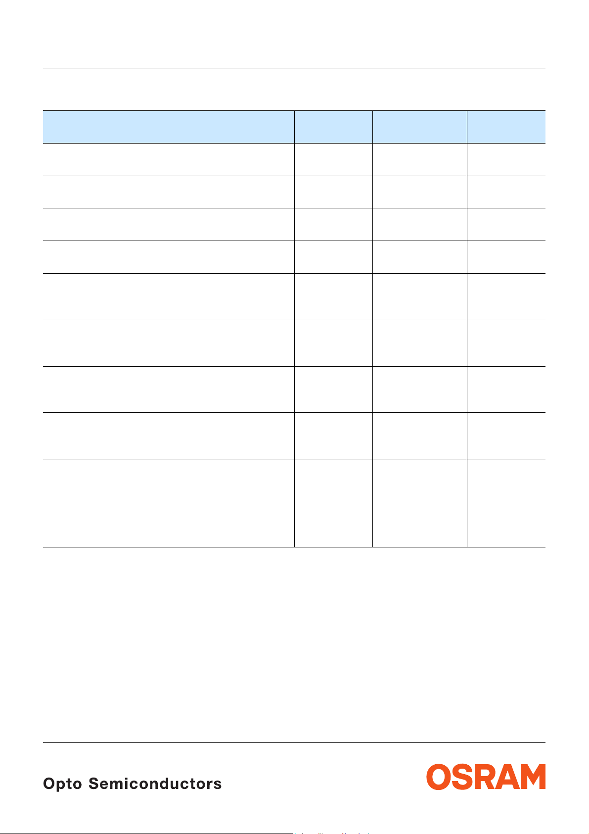
Grenzwerte
Maximum Ratings
LCW G6SP
Bezeichnung
Parameter
Betriebstemperatur
Operating temperature range
Lagertemperatur
Storage temperature range
Sperrschichttemperatur
Junction temperature
Sperrschichttemperatur
Junction temperature
Durchlassstrom
(min.)
Forward current (max.)
T
=25°C)
(
A
Stoßstrom
Surge current
t ≤ 10 μs, D = 0.005, T
3)
Sperrspannung
Reverse voltage3)
Seite 18
page 18
=25°C
A
(TA=25°C)
Symbol
Symbol
T
op
T
stg
T
j
T
j
I
F
I
F
I
FM
V
R
Wert
Value
Einheit
Unit
– 40 … + 110 °C
– 40 … + 110 °C
>150 for short
°C
term applications
+ 125 °C
30
250
mA
mA
750 mA
not designed for
V
reverse operation
Leistungsaufnahme
Power consumption
T
=25°C)
(
A
Wärmewiderstand
Thermal resistance
Sperrschicht/Umgebung
Junction/ambient
4) page 18
Sperrschicht/Lötpad
Junction/solder point
4)
Seite 18
P
R
R
tot
th JA
th JS
1075 mW
90
40
K/W
K/W
2007-08-09 3
Page 4
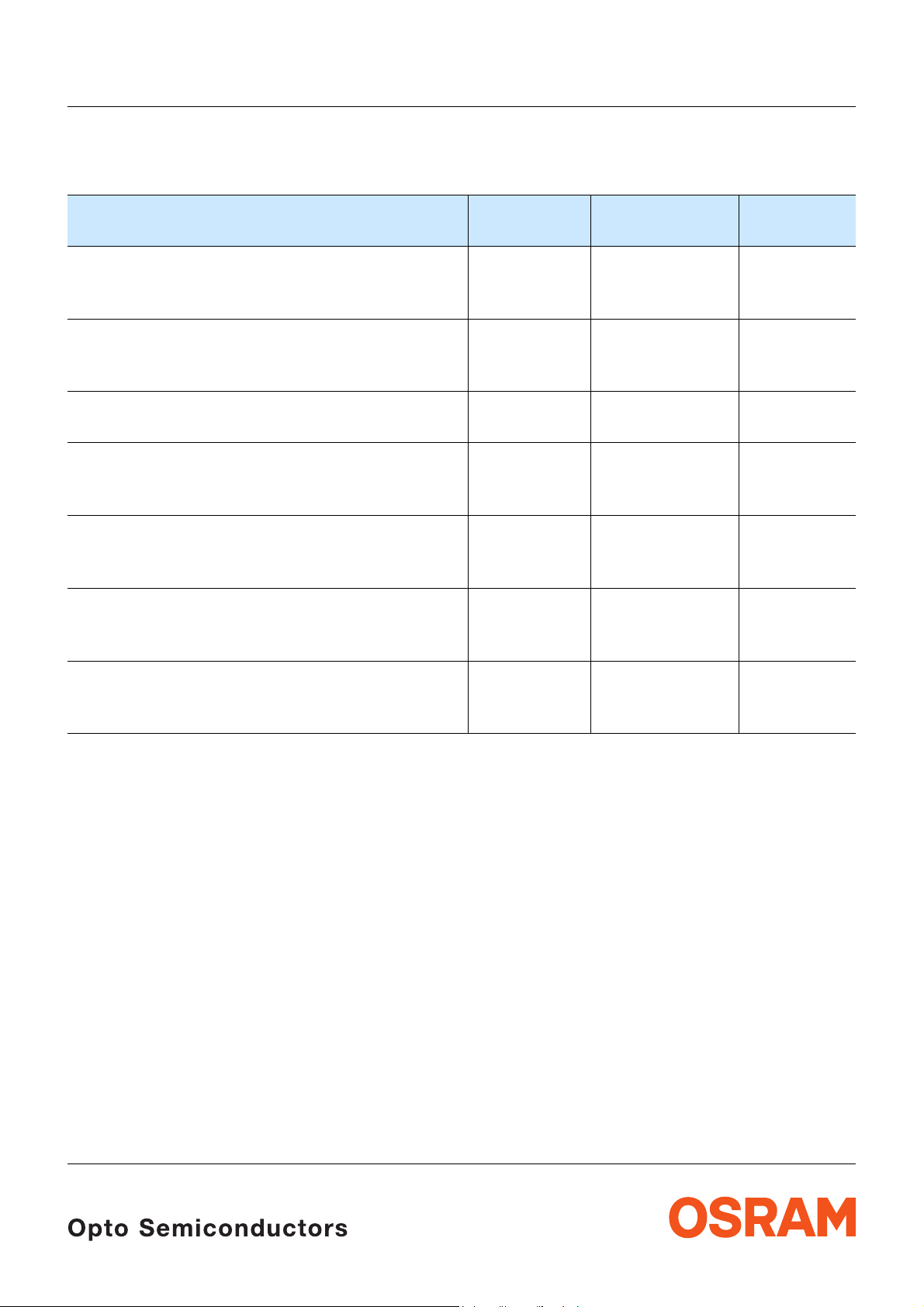
Kennwerte
Characteristics
T
= 25 °C)
(
A
Bezeichnung
Parameter
Farbkoordinate x nach CIE 1931
5) Seite 18
Chromaticity coordinate x acc. to CIE 1931
I
= 140 mA
F
Farbkoordinate y nach CIE 1931
5) Seite 18
Chromaticity coordinate y acc. to CIE 1931
I
= 140 mA
F
Abstrahlwinkel bei 50 %
Viewing angle at 50 %
Durchlassspannung
Forward voltage
I
= 140 mA (max.)
F
6) page 18
I
(Vollwinkel) (typ.)
V
I
V
6) Seite 18
(typ.)
(typ.)
5) page 18
(typ.)
5) page 18
(min.)
Sperrstrom (typ.)
Reverse current (max.)
V
= 5 V
R
Temperaturkoeffizient von
Temperature coefficient of
I
= 140 mA; –10°C ≤ T ≤ 100°C
F
V
F
V
F
(typ.)
Optischer Wirkungsgrad (typ.)
Optical efficiency
I
= 140 mA
F
* Einzelgruppen siehe Seite 5
Individual groups on page 5
LCW G6SP
Symbol
Symbol
x 0.42* –
y 0.40* –
2ϕ 120 Grad
V
F
V
F
V
F
I
R
I
R
TC
V
η
opt
Wert
Value
Einheit
Unit
deg.
2.9*
3.6
4.1
not designed for
reverse operation
V
V
V
μA
μA
–4.0 mV/K
24 lm/W
2007-08-09 4
Page 5
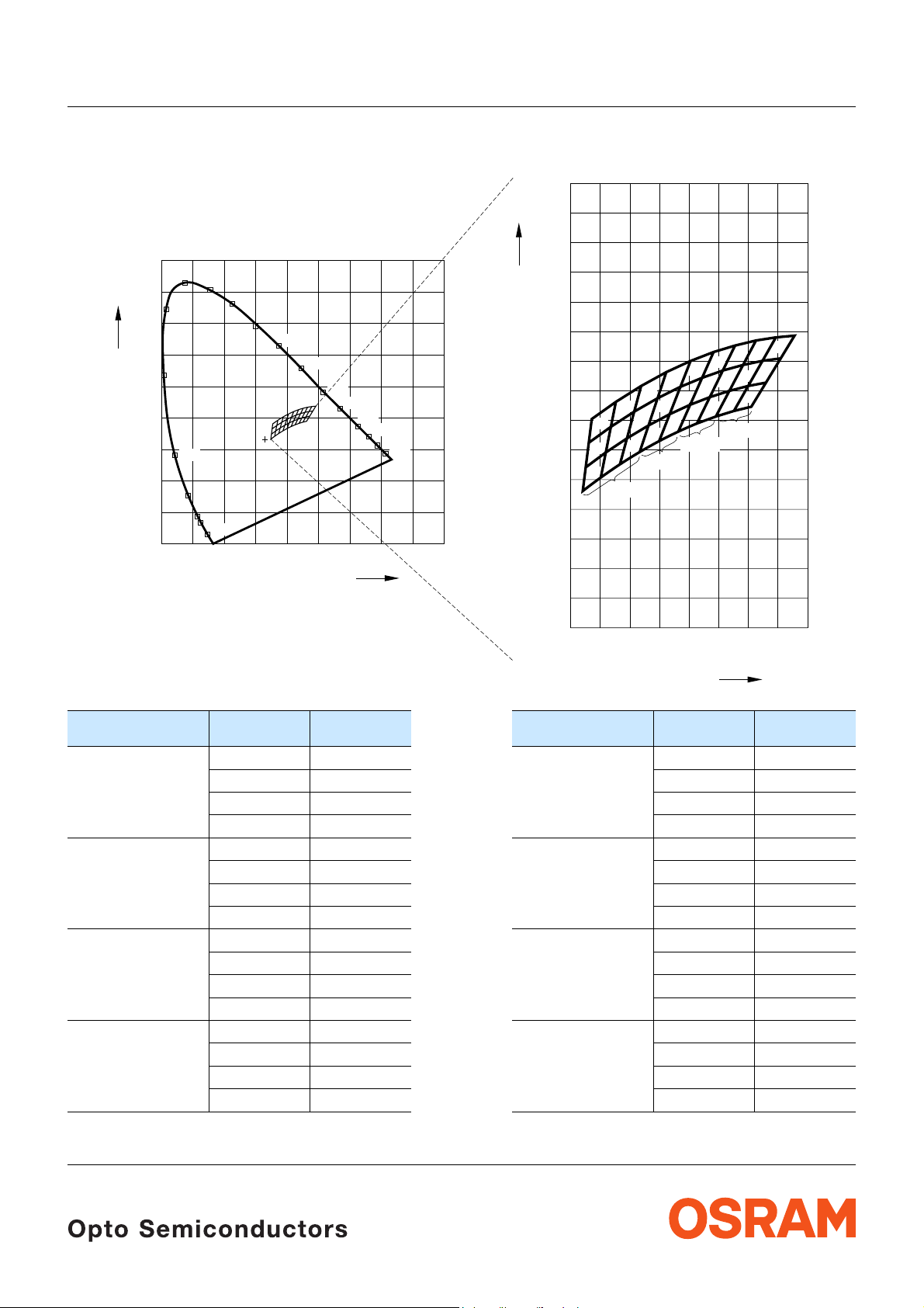
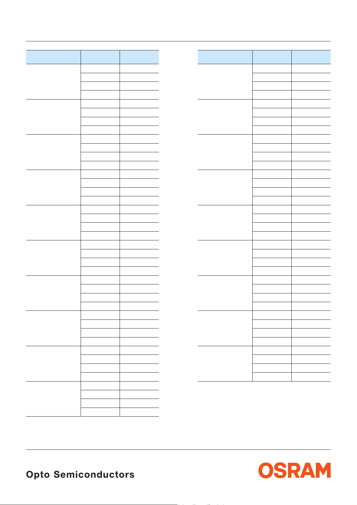
LCW G6SP
Farbortgruppen
5) Seite 18
Chromaticity Coordinate Groups
0.9
520
530
510
500
540
550
560
570
E
490
480
470
460
450
0.1 0.2 0.3 0.4 0.5 0.6 0.7 0.8 0.9
0
Cy
0.8
0.7
0.6
0.5
0.4
0.3
0.2
0.1
0
5) page 18
580
590
600
610
620
630
Cx
Cy
0.54
0.52
0.50
0.48
0.46
0.44
0.42
0.40
0.38
0.36
0.34
0.32
0.30
0.28
0.26
H5
H4
H3
J4 L3
K3
J3
4200 K
K5
K4
3500 K
L4J5
L5
M3
M5
N4
M4
N3
3000 K
N5
P3
P5
Q4
P4
Q3
2700 K
R5
Q5
R4
R3
0.24
0.38
0.36
0.34
Gruppe
Group
H3 0.348 0.332 M5 0.414 0.402
H4 0.350 0.348 N3 0.413 0.372
H5 0.352 0.365 N4 0.421 0.390
J3 0.360 0.341 N5 0.429 0.409
Cx Cy Gruppe
Group
0.360 0.341 0.429 0.409
0.364 0.358 0.436 0.426
0.350 0.348 0.421 0.420
0.364 0.358 0.425 0.378
0.367 0.376 0.434 0.396
0.352 0.365 0.421 0.390
0.367 0.376 0.434 0.396
0.371 0.392 0.443 0.414
0.354 0.381 0.429 0.409
0.373 0.350 0.443 0.414
0.378 0.368 0.451 0.430
0.364 0.358 0.436 0.426
0.42
0.40
Cx Cy
0.44
0.46
OHA02934
Cx
0.48
0.50
2007-08-09 5
Page 6
LCW G6SP
Gruppe
Group
J4 0.364 0.358 P3 0.425 0.378
J5 0.367 0.376 P4 0.434 0.396
K3 0.373 0.350 P5 0.443 0.414
K4 0.378 0.368 Q3 0.438 0.382
K5 0.383 0.386 Q4 0.447 0.400
L3 0.387 0.358 Q5 0.456 0.417
L4 0.393 0.376 R3 0.450 0.386
L5 0.399 0.395 R4 0.460 0.403
M3 0.400 0.366 R5 0.470 0.420
M4 0.407 0.384
Cx Cy Gruppe
Group
0.378 0.368 0.438 0.382
0.383 0.386 0.447 0.400
0.367 0.376 0.434 0.396
0.383 0.386 0.447 0.400
0.388 0.403 0.456 0.417
0.371 0.392 0.443 0.414
0.387 0.358 0.456 0.417
0.393 0.376 0.465 0.434
0.378 0.368 0.451 0.430
0.393 0.376 0.450 0.386
0.399 0.395 0.460 0.403
0.383 0.386 0.447 0.400
0.399 0.395 0.460 0.403
0.405 0.412 0.470 0.420
0.388 0.403 0.456 0.417
0.400 0.366 0.470 0.420
0.407 0.384 0.479 0.436
0.393 0.376 0.465 0.434
0.407 0.384 0.462 0.389
0.414 0.402 0.472 0.405
0.399 0.395 0.460 0.403
0.414 0.402 0.472 0.405
0.421 0.420 0.482 0.422
0.405 0.412 0.470 0.420
0.413 0.372 0.482 0.422
0.421 0.390 0.491 0.437
0.407 0.384 0.479 0.436
0.421 0.390
0.429 0.409
0.414 0.402
Cx Cy
2007-08-09 6
Page 7

LCW G6SP
Helligkeits-Gruppierungsschema
Brightness Groups
Helligkeitsgruppe
Brightness Group
BB
CA
CB
DA
DB
EA
Lichtstärke
Luminous Intensity
I
(mcd)
V
2240 ... 2800
2800 ... 3550
3550 ... 4500
4500 ... 5600
5600 ... 7100
7100 ... 9000
1) Seite 18
1) page 18
Lichtstrom
Luminous Flux
Φ
(mlm)
V
7500 (typ.)
9500 (typ.)
12000 (typ.)
15000 (typ.)
18950 (typ.)
24000 (typ.)
Anm.: Die Standardlieferform von Serientypen beinhaltet eine Sammelgruppe, die aus nur wenigen
Helligkeitsgruppen bestehen.
Einzelne Helligkeitsgruppen können nicht bestellt werden.
Note: The standard shipping format for serial types includes a grouping of all individual brightness
groups of only a few individual brightness groups.
Individual brightness groups cannot be ordered.
2) Seite 18
2) page 18
Gruppenbezeichnung auf Etikett
Group Name on Label
Beispiel: CB-J4-5
Example: CB-J4-5
Helligkeitsgruppe
Brightness Group
Farbortgruppe
Chromaticity Coordinate
Durchlassspannungsgruppe
Forward Voltage Group
Group
CB J4 5
Anm.: In einer Verpackungseinheit / Gurt ist immer nur eine Gruppe für jede Selektion enthalten.
Note: No packing unit / tape ever contains more than one group for each selection.
2007-08-09 7
Page 8

LCW G6SP
Relative spektrale Emission
Relative Spectral Emission
2) Seite 18
2) page 18
V(λ) = spektrale Augenempfindlichkeit / Standard eye response curve
I
= f (λ); TA = 25 °C; IF = 140 mA
rel
100
%
I
rel
80
60
V
λ
40
20
OHL02892
0
400
Abstrahlcharakteristik
450 500 550
2) Seite 18
Radiation Characteristic
I
= f (ϕ); TA = 25 °C
rel
50˚
60˚
70˚
80˚
90˚
2) page 18
nm650600 700
750
λ
0˚10˚20˚40˚ 30˚
ϕ
1.0
0.8
0.6
0.4
0.2
0
OHL01660
100˚
1.0 0.8 0.6 0.4
2007-08-09 8
0˚ 20˚ 40˚ 60˚ 80˚ 100˚ 120˚
Page 9

LCW G6SP
Durchlassstrom
Forward Current
I
= f (VF); TA = 25 °C
F
3
10
mA
I
F
2) Seite 18
2) page 18
5
2
10
5
1
10
3
3.4 3.8 4.2 4.6 5
Farbortverschiebung
2) Seite 18
Chromaticity Coordinate Shift
x, y = f (IF); TA = 25 °C
0.015
OHL02767
V
2) page 18
V
F
OHL02770
Relative Lichtstrom
2) 7) Seite 18
Relative Luminous Flux
Ι
V/ΙV
(140 mA)
I
V
= f (IF); TA = 25 °C
1
10
I
V
(140 mA)
0
10
5
-1
10
12
10 105
2) 7) page 18
OHL02768
10mA
I
F
3
Cx, Cy
0.005
0
Cx
-0.005
-0.010
Cy
-0.015
-0.020
-0.025
0
mA100 200 300 400 500
I
F
2007-08-09 9
Page 10

LCW G6SP
Relative Vorwärtsspannung
Relative Forward Voltage
ΔVF = VF - V
= f (Tj); IF = 140 mA
(25 °C)
F
2) Seite 18
2) page 18
0.50
V
Δ
V
F
0.35
0.30
0.25
0.20
0.15
0.10
0.05
0
-0.05
-0.10
-0.15
-0.20
-0.25
-60 -20-40 0 20 ˚C40 60 100
2)
Farbortverschiebung
Seite 18
Chromaticity Coordinate Shift
x, y = f (Tj); IF = 140 mA
0.010
OHL02772
T
2) page 18
j
OHL02782
Relative Lichtstärke
2) Seite 18
Relative Luminous Intensity
I
V/IV(25 °C)
= f (Tj); IF = 140 mA
1.4
I
V
I
V (25 ˚C)
1.0
0.8
0.6
0.4
0.2
-600-40 -20 0 20
2) page 18
OHL02725
˚C6040
100
T
j
Cx, Cy
0.005
Cx
0
Cy
-0.005
-0.010
-0.015
-0.020
-60 -20-40 0 20 40 60 100˚C
T
j
2007-08-09 10
Page 11

LCW G6SP
Maximal zulässiger Durchlassstrom
Max. Permissible Forward Current
I
= f (TS)
F
260
mA
I
F
OHL02777
220
200
180
160
T
A
T
S
140
120
100
80
60
40
T
temp. ambient
20
0
A
T
temp. solder point
S
0
20 40 60 80 110
˚C
T
I
Zulässige Impulsbelastbarkeit
= f (tp)
F
Permissible Pulse Handling Capability
Duty cycle
0.55
I
F
0.45
0.40
0.35
0.30
0.25
0.20
0.15
D = parameter, T
A
= 25 °C
A
D
=
0.005
0.01
0.02
0.05
0.1
0.2
0.5
1
OHL02778
Exemplarische durchschnittliche Lebens-
2)
dauer für mittlere Helligkeitsgruppe
Exemplary median Lifetime
2) page 17
Seite 17
for median Brightness Group
Bedingungen
mittlere
Einheit
Lebensdauer
Conditions
median
Unit
Lifetime
IF = 125 mA
T
= 25°C
A
= 100 mA
I
F
T
= 85°C
A
I
= 140 mA
F
T
= 125°C
S
T
= 150°C
J
I
= 140 mA
F
T
= 125°C
S
T
= 175°C
J
50.000 Betriebsstunden
operating hours
12.500 Betriebsstunden
operating hours
7.000* Betriebsstunden
operating hours
500* Betriebsstunden
operating hours
*The emitter die exhibits excellent performance
but slight package discoloration occurs at highest
temperatures.The median lifetime depends on the
application
I
Zulässige Impulsbelastbarkeit
= f (tp)
F
Permissible Pulse Handling Capability
Duty cycle
I
F
D = parameter, T
0.55
A
0.45
0.40
0.35
0.30
0.25
0.20
0.15
= 85 °C
A
t
P
=
D
T
OHL02780
t
P
T
D
0.005
0.01
0.02
0.05
0.1
0.2
0.5
1
I
F
=
0.10
D
0.05
0
2007-08-09 11
t
P
t
P
=
T
T
1010 10 10 10 10 10
I
F
0-1-2-3-4-5-6
2
10
s
t
p
0.10
0.05
0
10 10 10 10
-2-3-4-5-6
1010
10
t
20-1
10
s
p
Page 12

LCW G6SP
Maßzeichnung
8) Seite 18
Package Outlines
2.8 (0.110)
3.2 (0.126)
(ø2.6 (0.102))
8) page 18
3.5 (0.138)
3.1 (0.122)
2.8 (0.110)
2.6 (0.102)
A
C
A
AA
0.5 (0.020)
0.3 (0.012)
0.7 (0.028)
0.5 (0.020)
Package
marking
0.7 (0.028)
0.5 (0.020)
2.1 (0.083)
1.7 (0.067)
0...0.15 (0.006)
0.4 (0.016)
0.9 (0.035)
3.6 (0.142)
3.2 (0.126)
Anmerkung:
ESD Schutzdiode leuchtet
Note:
EDS protection diode emits light
Protection Diode
A A
C
AA
GPLY6117
Kathodenkennung: Markierung
Cathode mark: mark
Gewicht / Approx. weight: 40 mg
Gurtung / Polarität und Lage
8) Seite 18
Method of Taping / Polarity and Orientation
4 (0.157)1.5 (0.059)
3.5 (0.138)
2 (0.079)
8 (0.315)
8) page 18
Verpackungseinheit 1000/Rolle, ø180 mm
Packing unit 1000/reel, ø180 mm
Cathode/Collector Side
5.5 (0.217)
1.75 (0.069)
3.7 (0.146)
2.05 (0.081)
12 (0.472)
1.5 (0.059)
2˚... 3˚
0.3 (0.012) max.
OHTY1754
2007-08-09 12
Page 13

LCW G6SP
Empfohlenes Lötpaddesign
Recommended Solder Pad
min 9 mm per anode pad for
improved heat dissipation
A
C
A
A
A
Package
marking
8) 9) Seite 18
8) 9) page 18
2
1.4 (0.055)
4.7 (0.185)
IR Reflow Löten
IR Reflow Soldering
0.8 (0.031)
0.8 (0.031)
0.35 (0.014)
0.6 (0.024)
Lötstopplack
Solder resist
Anm.: Das Gehäuse ist für Ultraschallreinigung nicht geeignet
Note: Package not suitalbe for ultra sonic cleaning
0.35 (0.014)
OHLP4927
Package
marking
2007-08-09 13
Page 14

LCW G6SP
Lötbedingungen Vorbehandlung nach JEDEC Level 2
Soldering Conditions Preconditioning acc. to JEDEC Level 2
IR-Reflow Lötprofil für bleifreies Löten (nach J-STD-020B)
IR Reflow Soldering Profile for lead free soldering (acc. to J-STD-020
B)
300
˚C
250
T
200
150
100
50
0
Wellenlöten (TTW)
TTW Soldering
9) page 18
0
9)
255 ˚C
240 ˚C
217 ˚C
Ramp Up
3 K/s (max)
25 ˚C
Seite 18
OHLA0687
Maximum Solder Profile
Recommended Solder Profile
Minimum Solder Profile
10 s min
30 s max
Ramp Down
6 K/s (max)
120 s max
50 100 150 200 250 300
100 s max
260 ˚C
245 ˚C
235 ˚C
s
+0 ˚C
-5 ˚C
±5 ˚C
+5 ˚C
-0 ˚C
t
(nach CECC 00802)
(acc. to CECC 00802)
300
C
250
T
235 C
C... 260
10 s
2. Welle
2. wave
200
1. Welle
1. wave
150
ca 200 K/s
5 K/s
CC... 130100
100
Zwangskühlung
2 K/s
50
forced cooling
0
0
50 100 150 200 250
2007-08-09 14
OHLY0598
Normalkurve
standard curve
Grenzkurven
limit curves
2 K/s
s
t
Page 15

Barcode-Produkt-Etikett (BPL)
e
Barcode-Product-Label (BPL)
LCW G6SP
Gurtverpackung
Tape and Reel
OSRAM Opto
Semiconductors
(6P) BATCH NO: Batch Number
Bar Code
Lot Number(1T) LOT NO: (9D) D/C:Date Code
Bar Code
(X) PROD NO: Product Code
D
0
P
0
P
2
Lx xxxx
Product Name
RoHS Compliant
Product Quantity per Reel(Q)QTY:
Bar Code
Sampl
W
1
±0.25
13.0
FE
A
N
W
Bin1: Bin Information Color 1
Bin2:
Bin3:
ML2Temp ST
260 C RT
Additional TEXT
R077 DEMY
PACKVAR: Packing Type
X - X - X(G) GROUP:
Forward Voltage Group
Wavelength Group
Brightness Group
OHA12043
P
1
Direction of unreeling
W
2
Label
Gurtvorlauf:
Leader:
Gurtende:
Trailer:
Direction of unreeling
400 mm
400 mm
160 mm
160 mm
OHAY0324
Tape dimensions in mm (inch)
W P
+ 0.3
12
– 0.1
0
4 ± 0.1
(0.157 ± 0.004)
P
1
8 ± 0.1
(0.315 ± 0.004)
P
2
2 ± 0.05
(0.079 ± 0.002)
D
0
1.5 + 0.1
(0.059 + 0.004)
E F
1.75 ± 0.1
(0.069 ± 0.004)
5.5 ± 0.05
(0.217 ± 0.002)
Reel dimensions in mm (inch)
A W N
min
W
1
W
2 max
180 (7) 12 (0.472) 60 (2.362) 12.4 + 2 (0.488 + 0.079) 18.4 (0.724)
2007-08-09 15
Page 16

LCW G6SP
Trockenverpackung und Materialien
Dry Packing Process and Materials
Moisture-sensitive label or print
L
E
V
l
E
e
e
b
e
L
a
s
l
,
).
e
k
H
d
n
o
a
l
R
c
b
(
r
If
a
y
b
.
it
d
H
i
m
R
u
%
h
0
e
6
e
/
v
i
g
d
t
C
a
˚
re
la
k
a
0
c
e
r
S
f
3
a
N
E
r
s
R
n
p
_
<
i
%
IV
in
f
O
k
0
O
T
s
o
to
T
I
a
r
ta
9
I
e
.
s
S
u
s
C
n
d
)
r
r
<
p
n
o
e
N
o
U
(
e
T
o
u
t
d
rs
H
io
d
E
,
c
o
D
c
t
g
n
s
i
u
o
e
r
2
g
N
j
U
S
a
d
o
in
c
˚C
H
u
7
a
b
s
n
O
E
8
H
o
e
5
C
b
u
s
o
t
A
is
T
h
C
T
IS
S
O
O
M
T
P
O
m
4
2
:
d
,
g
d
a
lo
e
b
f
n
d
re
e
e
l
p
e
e
a
s
s
o
e
a
,
s
i
h
k
s
n
g
n
-p
i
F
r
a
la
in
e
o
b
b
h
f
p
%
it
li
f
s
.
i
I
a
0
f
p
l
h
w
1
t
v
e
,
m
d
_
<
r
h
e
e
w
r
e
te
t
t
i
S
o
ft
a
n
l
u
y
.
f
n
u
A
I
q
d
1
d
e
o
.
r
o
s
e
y
i
re
r
t
2
b
i
M
o
s
b
t
)
id
e
2
a
S
s
r
m
i
ic
)
u
v
o
b
g
e
e
H
a
c
in
D
)
n
k
2
.
a
)
a
re
3
b
e
b
f
f
I
a
re
.
e
4
s
g
a
B
e
t
a
D
M
4
˚
C
R
e
s
4
H
e
I
c
a
±
U
c
2
0
m
e
e
y
M
E
s
h
t
n
o
e
c
i
r
v
o
e
,
w
r
a
b
e
ti
r
o
.
o
l
H
R
n
i
k
a
o
t
b
a
m
c
i
t
d
o
n
u
q
/
e
C
r
P
I
e
t
a
d
l
t
d
n
a
r
u
t
is
t
o
s
i
o
i
M
o
M
M
6
i
d
o
r
t
C
b
4
r
h
˚
e
o
l
r
im
<
t
l
it
t
.
p
i
o
3
c
m
e
t
)
t
r
i
o
2
w
t
w
n
a
l
o
C
l
t
t
im
˚
fa
r
e
.
F
a
t
l
t
lo
a
o
e
a
a
a
r
ic
r
F
l
o
t
d
v
th
l
o
i
u
e
n
a
F
o
u
s
f:
d
l
b
4
i
e
e
w
q
e
l
r
a
F
,
d
l
i
5
c
e
lo
e
g
a
n
l
o
v
e
e
s
n
5
r
i
e
e
i
e
b
d
t
l
h
v
p
6
L
o
n
e
e
te
e
l
c
e
v
u
w
e
e
a
k
e
r
L
e
o
s
d
v
a
%
e
L
l
tu
r
m
e
b
e
0
a
s
u
i
r
1
t
e
L
re
m
e
r
o
o
s
e
u
s
f
i
>
t
r
fo
M
,
o
s
u
3
i
k
is
e
t
3
M
o
n
b
is
0
a
,
rd
M
o
l
g
a
D
M
b
r
T
if
C
(
r
.
a
S
t
r
s
e
e
a
k
s
J
e
Y
r
e
,
C
1
u
e
Y
d
E
o
e
>
1
W
D
H
ir
e
4
E
8
J
m
e
6
ti
1
:
m
e
r
i
d
o
t
m
e
r
e
i
o
t
l
o
n
m
i
r
F
o
e
t
l
o
p
r
F
o
o
l
o
F
o
e
l
1
l
F
2
im
e
a
l
v
2
e
e
l
v
3
L
e
e
l
v
e
L
e
e
v
e
L
r
e
u
L
re
e
u
t
r
s
u
t
is
o
M
A
R
S
O
Desiccant
Anm.: Feuchteempfindliche Produkte sind verpackt in einem Trock enbeutel zusammen mit einem Trockenmittel und
einer Feuchteindikatorkarte
Bezüglich Trockenverpackung finden Sie weitere Hinweise im Internet und in unsere m Short Form Catalog im
Kapitel “Gurtung und Verpackung” unter dem Punkt “Trockenverpackung”. Hier sind Normenbezüge, unter
anderem ein Auszug der JEDEC-Norm, enthalten.
Note: Moisture-senisitve product is packed in a dry bag containing desiccant and a humidity card.
Regarding dry pack you will find further information in the internet and in the Short Form Catalog in chapter
“Tape and Reel” under the topic “Dry Pack”. Here you will also find the normative references like JEDEC
Kartonverpackung und Materialien
Transportation Packing and Materials
Barcode label
Do not eat.
Avoid metal contact.
Discard if circles overrun.
bag opening.
Please check the HIC immidiately after
check dot
WET
Comparator
bake units
15%
examine units, if necessary
If wet,
bake units
10%
examine units, if necessary
If wet,
change desiccant
5%
parts still adequately dry.
If wet,
MIL-I-8835
Humidity Indicator
OSRAM
Humidity indicator
Barcode label
OHA00539
Barcode label
-1-20
Bin1: P-1-20
R
Bin2: Q
Bin3:
Temp ST
220 C
ML
240 C R
2
260 C RT
2a
LSY T676
3
Additional TEXT
R077
Multi TOPLED
L
E
V
l
E
e
e
b
e
L
s
.
la
)
,
e
k
H
d
n
o
la
(R
c
b
r
If
a
b
.
ity
H
id
R
m
u
%
h
0
e
e
/6
g
d
tiv
a
re
˚C
la
k
a
c
0
e
S
fr
a
3
N
E
r
s
R
_
<
in
p
%
IV
in
f
O
k
0
to
T
a
IT
ta
IO
S
C
n
N
o
U
T
d
E
D
c
n
g
N
U
S
a
a
b
O
E
C
u
b
C
A
R
s
˚
I
c
U
is
0
e
M
o
4
T
h
C
r
E
T
p
IS
.
ill b
S
t
t <
)
O
w
n
O
a
t
˚C
M
le
s
T
t
a
a
a
P
l
th
iv
th
e
n
O
u
s
b
o
w
q
e
la
e
lo
m
ic
e
r
e
v
4
d
e
2
b
, o
o
:
n
e
, d
g
u
w
c
e
r
d
a
o
s
%
a
e
b
flo
m
e
0
n
e
b
d
e
r
1
e
re
le
p
e
e
>
a
s
fo
r tim
o
e
a
e
o
, s
is
.
s
h
k
is
lo
0
H
p
, b
n
rd
g
-
F
g
in
r-
a
a
R
in
la
D
o
in
b
T
C
p
%
k
ith
r
.
is
If b
t.
a
0
a
-S
p
w
lf life
to
e
1
e
b
J
, v
a
m
d
_
<
r th
,
h
m
e
C
w
ic
t
t
te
d
ire
t
d
E
fte
o
a
n
e
u
y
. S
flo
D
u
ir
A
In
q
d
1
n
d
e
o
u
.
r
E
o
e
q
r
2
is
re
b
ity
/J
M
s
b
to
)
:
id
C
re
e
a
2
d
S
r
m
ic
IP
)
e
is
u
v
lo
o
b
n
g
e
e
F
a
e
c
in
D
) H
p
n
te
k
F
.
a
o
) 2
e
a
a
r
3
b
e
b
fe
l d
l 1
If
a
e
re
a
.
l 2
e
tim
v
4
e
s
d
e
l 2
v
n
g
e
L
e
l 3
v
a
a
e
L
e
r
e
B
e
v
t
e
tu
r
L
e
a
is
tu
D
L
re
o
e
is
tu
r
M
o
is
tu
M
o
is
M
o
M
rs
o
9
e
s
u
s
d
).
r
<
je
s
e
fa
in
t
3
r tim
o
lo
F
r
n
o
(p
e
u
te
c
g
in
s
r
to
c
, if:
g
n
e
h
w
r
fo
3
la
b
if
(
e
im
t
r
o
tim
r
o
lo
o
lo
F
s
r
d
, o
o
H
s
itio
u
o
C
r
2
d
o
c
H
u
˚
n
7
8
H
o
o
te
5
e
4
H
a
4
c
±
e
y
d
2
tim
C
h
e
r
˚
6
it
o
3
e
r tim
w
lo
l
o
tim
t 2
r
.
F
a
lo
tim
o
e
a
r
r
F
tic
d
lo
o
u
n
a
F
d
lo
4
e
e
e
r
l
F
5
c
e
id
a
l
o
v
r
e
e
is
l 5
v
p
e
L
te
e
l 6
e
v
a
k
e
re
L
e
d
v
a
u
e
l
t
r
L
e
b
a
e
is
tu
L
r
e
o
s
u
i
t
re
, s
M
o
is
k
tu
M
o
n
is
M
o
M
r
a
r
s
e
a
k
e
Y
rs
e
u
e
Y
1
o
>
W
H
1
4
8
e
6
1
e
e
r tim
0
2
0
1
2
-
-
1
P
-
:
1
Q
T
:
in
2
S
B
:
p
in
3
R
B
m
Y
in
C
e
R
M
B
T
T
0
C
E
2
R
T
2
L
D
0
X
4
C
M
2
E
0
6
2
l T
2
a
a
2
LSY T676
n
R18
3
itio
:
d
R
d
7
A
A
7
V
0
K
R
Multi TOPLED
C
P-1+Q-1
A
:
P
P
U
O
R
G
)
G
(
8
0144
to
9
:
9
p
rs
/C
1
D
to
)
2
O
c
D
0
M
0
(9
du
1
A
n
2
o
:
R
O
2000
ic
S
:
N
Y
m
O
H
T
e
C
S
T
)Q
A
Q
(
B
)
P
123GH1234
6
:
(
O
N
T
1
Muster
O
0
L
)
0 245
T
11
(1
:
O
N
D
O
R
P
)
X
(
S
O
S
PACKVAR:
o
0144
t
p
rs
O
to
c
u
M
(9D) D/C:
d
A
n
210021998
o
R
2000
ic
m
e
(Q)QTY:
123GH1234
(6P) BATCH NO:
245
1
Muster
0
0
11
(1T) LOT NO:
(X) PROD NO:
Packing
Sealing label
Dimensions of transportati on bo x in mm (inch)
Breite / Width Länge / length Höhe / height
±5 (7,874 ±0,1968±)200 ±5 (7,874 ±0,1968) 30 ±5 (1,1811 ±0,1968)
200
2007-08-09 16
Barcode label
DEMY
R18
P-1+Q-1
(G) GROUP:
OSRAM
OHA02044
Page 17

LCW G6SP
Revision History: 2007-08-09
Previous Version: 2007-07-31
Page Subjects (major changes since last revision) Date of change
1, 3, 14 Infonote OS-IN-2007-016 2007-07-31
Patent List
Patent No.
US 6 066 861
US 6 277 301
US 6 245 259
Attention please!
The information describes the type of component and shall not be considered as assured characteristics.
Terms of delivery and rights to change design reserved. Due to technical requirements components may contain
dangerous substances. For information on the types in question please contact our Sales Organization.
If printed or downloaded, please find the latest version in the Internet.
Packing
Please use the recycling operators known to you. We can also help you – get in touch with your nearest sales office.
By agreement we will take packing material back, if it is sorted. You must bear the costs of transport. For packing
material that is returned to us unsorted or wh ich we are not obliged to accept, we shall hav e to invoice you for any costs
incurred.
Components used in life-support devices or systems must be expressly authorized for such purpose!
components
OSRAM OS.
2007-08-09 17
10) page 18
may only be used in life-support devices or systems
11) page 18
with the express written approval of
Critical
Page 18

LCW G6SP
Fußnoten:
1)
Helligkeitswerte werden mit einer
Stromeinprägedauer von 25 ms und einer
Genauigkeit von ± 11% ermittelt.
2)
Wegen der besonderen Prozessbedingungen bei der
Her- stellung von LED können typische oder
abgeleitete technische Parameter nur aufgrund
statistischer Werte wiedergegeben werden. Diese
stimmen nicht notwendigerweise mit den Werten
jedes einzelnen Produktes überein, dessen Werte sich
von typischen und abgeleiteten Werten oder typische n
Kennlinien unterscheiden können. Falls erforderlich,
z.B. aufgrund technischer Verbesserungen, werden
diese typischen Werte ohne weitere Ankündigung
geändert.
3)
Die LED kann kurzzeitig in Sperrichtung betrieben
werden.
4)
Montage auf PC-Board - Metallkernplatine, Fläche
950 mm² pro LED. Für weitere Informationen siehe
Applikationsschrift im Internet (www.osram-os.com).
5)
Farbortgruppen werden mit einer Stromeinprägedauer
von 25 ms und einer Genauigkeit von ±0.01 ermittelt.
6)
Spannungswerte werden mit einer
Stromeinprägedauer von 1 ms und einer Genauigkeit
von ±0,1 V ermittelt.
7)
Im gestrichelten Bereich der Kennlinien muss mit
erhöhten Helligkeitsunterschieden zwischen
Leuchtdioden innerhalb einer Verpackungseinheit
gerechnet werden.
8)
Maße werden wie folgt angegeben: mm (inch)
9)
Gehäuse hält TTW-Löthitze aus nach CECC 00802.
Das Gehäuse ist auf Grund der Beinchengeometrie
nicht für TTW-Löten empfohlen, da sich Lötbrücken
bilden können.
10)
Ein kritisches Bauteil ist ein Bauteil, das in
lebenserhaltenden Apparaten oder Systemen
eingesetzt wird und dessen Defekt voraussichtlich zu
einer Fehlfunktion dieses lebenserhaltenden
Apparates oder Systems führen wird oder die
Sicherheit oder Effektivität dieses Apparates oder
Systems beeinträchtigt.
11)
Lebenserhaltende Apparate oder Systeme sind für
(a) die Implantierung in den menschlichen Körper
oder
(b) für die Lebenserhaltung bestimmt.
Falls sie versagen, kann davon ausgega ngen werden,
dass die Gesundheit und das Leben des Patienten in
Gefahr ist.
Remarks:
1)
Brightness groups are tested at a current pulse
duration of 25 ms and a tolerance of ± 11%.
2)
Due to the special conditions of the manufacturing
processes of LED, the typical data or calculated
correlations of technical parameters can only reflect
statistical figures. These do not necessarily
correspond to the actual parameters of each single
product, which could differ from the typical data and
calculated correlations or the typical characteristic
line. If requested, e.g. because of technical
improvements, th ese typ . data w ill be changed without
any further notice.
3)
Driving the LED in reverse direction is suitable for
short term application.
4)
Mounted on PC board - metall core PCB, area of
950 mm² per LED. For further information please find
the application note on our web site
(www.osram-os.com).
5)
Chromaticity coordinate groups are tested at a current
pulse duration of 25 ms and a tolerance of ±0.01.
6)
Forward voltages are tested at a current pulse
duration of 1 ms and a tolerance of ±0.1 V.
7)
In the range where the line of the graph is broken , you
must expect higher brightness differences between
single LEDs within one packing unit.
8)
Dimensions are specified as follows: mm (inch).
9)
Package able to withstand TTW-soldering heat acc. to
CECC 00802.
The package is not recommended for TTW soldering
because a short cut between the contacts can occu re.
10)
A critical component is a component used in a
life-support device or system whose failure can
reasonably be expected to cause the failure of that
life-support device or system, or to affect its safety or
the effectiveness of that device or system.
11)
Life support devices or systems are intended
(a) to be implanted in the human body,
or
(b) to support and/or maintain and sustain human life.
If they fail, it is reasonable to assume that the health
and the life of the user may be endangered.
Published by
OSRAM Opto Semiconductors GmbH
Wernerwerkstrasse 2, D-93049 Regensburg
www.osram-os.com
© All Rights Reserved.
2007-08-09 18
 Loading...