

Page 1
PREPARED BY: DATE:
Lvl -WI
-7’- tieda
.
APPROVED BY: DATE: ELECTRONIC COMPONENTS GROUP
Jk / ,t/97 SHARP CORPOFNI’ION
“LAS
3-F
DEVICE SPECIFICATION FOR
- :::
SPlkIFICATION
SPECNo. DC396029
REPRESENTATIVE DIVISION:
Opto-Electronic Devices Division
Light Emitting Diode
MODEL No.
GL5ZS302BOS
1. These specification sheets include materials protected under the copyright of Sharp Corporation (“Sharp”).
Please do not reproduce or cause anyone to reproduce them without Sharp’s consent.
2. When using this product, please observe the absolute maximum ratings and the instructions for use outlined
in these specification sheets, as well as the precautions mentioned below. Sharp assumes no responsibility
for any damage resulting from use of the product which does not comply with the absolute maximum ratings
and the instructions included in these specification sheets, and the precautions mentioned below.
(Precautions)
(1) This products is designed for use in the following application areas:
* OA equipment * Audio visual equipment
* Telecommunication equipment (Terminal)
* Tooling machines * Computers
r
If the use of the product in the above application areas is for equipment listed in paragraphs
(2) or (3). please be sure to observe the precautions given in those respective paragraphs.
(2) Appropriate measures, such as fail-safe design and redundant design considering
the safety design of the overall system and equipment, should be taken to ensure reliability
and safety when this product is used for equipment which demands high reliability and
safety in function and precision, such as ;
* Transportation control and safety equipment (aircraft, train, automobile etc.)
* Traffic signals
* Other safety equipment
[
(3) Please do not use this product for equipment which require extremely high reliability
and safety in function and precision, such as ;
* Space equipment * Telecommunication equipment (for trunk lines)
* Nuclear power control equipment * Medical equipment
i
(4) Please contact and consult with a Sharp sales representative if there are any questions
regarding interpretation of the above three paragraphs.
3. Please contact and consult with a Sharp sales representative for any questions about this product.
* Gas leakage sensor breakers * Rescue and security equipment
* Home appliance
* Measuring equipment
J&16/99
10 Pages
1
I
1
CUSTOMER’S APPROVAL
DATE:
BY:
DATE:
PRESENTED BY:
M.Katoh,
Department General Manager of
Engineering Dept.m
Opto-Electronic Devices Division
Electronic Components Group
SHARP CORPORATION
&,i //c$
9-i ./kzzzq2 ,
/99)’
Page 2
MODEL No.
GL5ZS302BOS
GL5ZS302BOS Snecifkation
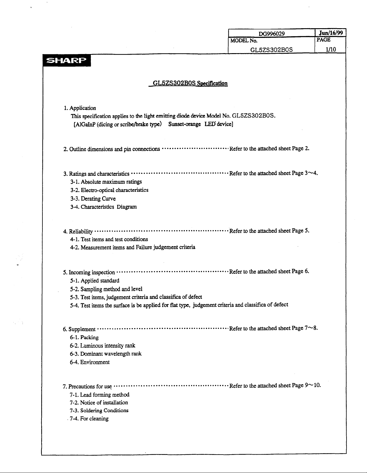
1. Application
This specification applies to the light emitting diode device Model No. GL5ZS302BOS.
[AlGaInF (dicing or scribebake type)
Sunset-orange
LED device]
x996029
Junl16l99
PAGE
l/10
2. Outline dimensions and pin connections
3. Ratings and characteristics
. . . . . . . . . . . . . . . . . . . . . . . . . . . . . . . . . . . . . . . .
. . . . . ..*...................a
Refer to the attached sheet Page 2.
Refer to the attached sheet Page 3-4.
3- 1. Absolute maximum ratings
3-2. Electra-optical characteristics
3-3. Derating Curve
3-4. Characteristics Diagram
4. Reliability
. . . . . . . . . . . . . . . . . . . . . . . . . . . . . . . . . . . . . . . . . . . . . . . . . . . . . . .
Refer to the attached sheet Page 5.
4-l. Test items and test conditions
4-2. Measurement items and Failure judgement criteria
. .
5. Incoming inspection
. . . . . . . . . . . . . . . . . . . . . . . . . . . . . . . . . . . . . . . . . . . . . .
Refer to the attached sheet Page 6.
5- 1. Applied standard
5-2. Sampling method and level
5-3. Test items, judgement criteria and classifica of defect
5-4. Test items the surface is be applied for flat type, judgement criteria and classifica of defect
6. Supplement
. . . . . . . . . . . . . . . . . . . . . . . . . . . . . . . . . . . . . . . . . . . . . . . . . . . . . .
6-1. Packing
6-2. Luminous intensity rank
6-3. Dominant wavelength rank
6-4. Environment
7. Precautions for usq
. . . . . . . . . . . . . . . . . . . . . . . . . . . . . . . . . . . . . . . . . . . . . . .
7-l. Lead forming method
7-2. Notice of installation
7-3. Soldering Conditions
.7-4. For cleaning
Refer to the attached sheet Page 7-8.
Refer to the attached sheet Page 9+ 10.
Page 3
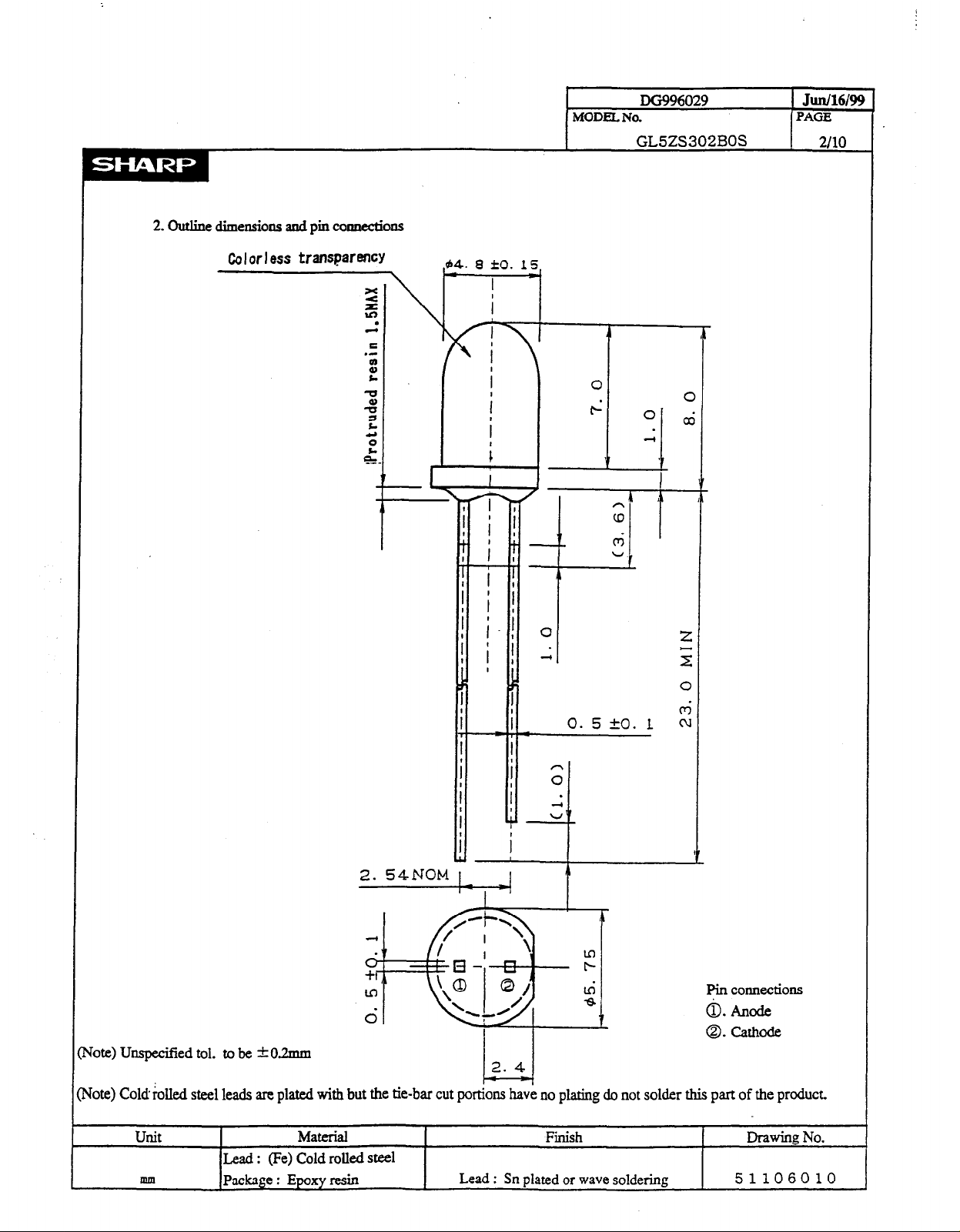
2. Outline dimensions and pin comectiolls
MODEL No.
DC3996029
GL5ZS302BOS
Jun/16/9!3
PAGE
2110
Colorless transparency
-
94. 0 co. 15
I
i
I
i
i
i r-’
i
I
A.’
j i i
t i t
’ I
i i i
i i.i o
iii *
j
I ’
j
5
I I
i
i
i
I +
i ;
i .
; G
I
0
O
CD
0
A’
0. 5 20. 1
C
a
2
2
0
G
Vote) Umpecified tol. to be +0.2mm
qote) Cold klled steel leads are plated with but ti
Unit
mm
Lead : (Fe) Cold rolled steel
Package : Epoxy resin
Material
i i
LL
T
pin coIlnections
0. Anode
0. cathode
2. 4
L---J
ie
tie-bar cut portions have no plating do not solder this part of the product.
Fish
Lead : Sn plated or wave soldering
Drawing No.
51106010
Page 4
3. Ratings and characteristics
I
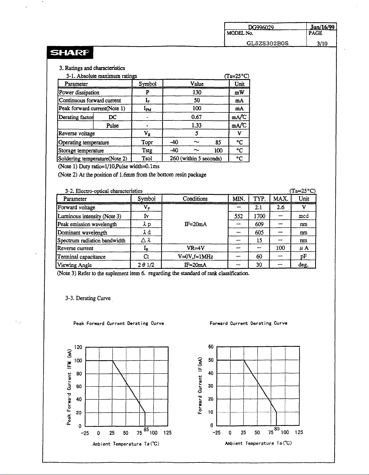
(Note 1) Duty ratio=l/lOJUse width=O.lms
(Note 2) At the position of 1.6~ from the bottom resin package
MODEL. No.
I
DG9@329
GL5ZS302BOS
Julll16/99
PAGE
I 3110
I
3-2. Electra-optical characteristics
I Parameter i Svmbol 1
Conditions
Spectrum radiation bandwidth A 1
Reverse current
Terminal capacitance
IViewing Angle 1
1,
ct V=OV,f=MHz - 60 - pF
2eii2
1 lF=2omA
VR=W 100 /.JA
(Note 3) Refer to the suplement item 6. regarding the standard of rank classification.
I
3-3. Derating Curve
Peak Forward Current Derating Curve
Forward Current Derating Curve
60
50
(Ta=25”C)
7ia. KTYP. IMAx.l Unity I
-
-
15 - run
1 30 1 - 1 deg. 1
80
60
-25 0 25 50
Ambient Temperature Ta(“CI
75°J100 125
40
30
20
10
0
-25 0 25 50
Ambient Temperature Ta (“C)
75a5 100 125
Page 5

DG996029
Jun/16/99
MODEL No. PAGE
GL5ZS302BOS
4110
Peak Forward Current vs. Duty Ratio
10
l/100 l/10
Duty Raito DR
1 10
3-4. Characteristics Diagram(typ) (Note 1)
Forward Current vs.Forward Voltage
100
I
10
0. 1
1 1.2 1.4 1.6 1.8 2 2.2 2.42.6
Forward Vo I tage VF (VI
(Ta=25%)
(Ta=25”C)
Relative Luminous Intensity
vs. Ambient Temperature
( I F=2OmA)
$
.-
c*
s
c
ii
ea
.- v
5
-I
z
.-
%I
E
-
1000
liiiiiiii j 1 j j / / / //
iiiiiiil
100
I i i i
10
-60-40-20 0 20 40 60
Ambient Temprature Ta (“C).
80 100 120
1
Relative Ominous Intensity vs. Froward Voltaca
(Ta=ZS’C)
100
5
.-
Ln
2
:
2
O-
.r 5
E
3
,”
.-
z
1000
100
10
1
0. 1
0. 1 1
10
Forward Current IFGnAI
(Note 1) Above characteristic data are typical data and not a guarantteed data.
Page 6

4. Reliability
The reliability of products shall be satisfied with items listed below.
MODEL No.
GL5ZS302BOS
DG996029 1 .Junl16/9!3
) PAGE
5110
4-l. Test items and test conditions
I
Test items
Solderability
soldering
temoerature
~ I
Mechanical shock
I
23025°C. 5s
I
Prior disnosition : Div in rosin flux
260”5z, 5s
15 OOOm/s2. 0.5ms.
3times /S&Y&Z direction
Test conditions
Variable frequency 200m/s2, 100 to 2 Ooo to lOOBz/sweep for 4min.
vibration ,4tirnes/iX&Y &Z direction
Terminal strength
(Tension)
Terminal strength
(Bending)
Weight:lON, Ss/each terminal
WeightH,O” --f 90” +OO+-90” + 0”
/each terminal
Temperature cycling ~-4O~(3Omin)~+lOO”c(30min),3O cycles
Hi@’ temP* md Qh
Ta=+&)~, gO%m, t=l@)oh
humidity storage
Iigh temperature storage Ta=lOO”c, t=lOOOh
Confidence level: 90%
n=ll, C=O 20
I I
n=ll, C=O 20
n=ll, C=O 20
n=ll. 60 20
n=22, C=O 10
n=22, C=O 10
n=22, C=O 10
ow temperature storage Ta=-40%. t=lOOOh
Operation lie
I
Ta=‘Z”C. IrMAX, t=lOOOh *3
4-2. Measurement items and Failure judgement criteria * 1
Measurement Symbol Failure judgement criteria *2
Forward voltage
Reverse current
Luminous intensity
VF
IR
IV
Iv > The first stage value X 2.0 or The
VF > u.s.,a. x 1.2
IR > U.S.L. x 2.0
first stage
s Solderability : Sol&r shall be adhere at the area of 95% or more of dipped portion.
z Terminal strength : Package is not destroyed, and terminal is not slack.
* 1: Measuring condition is in accordance with specification.
*2: U.S.L. is shown by Upper Specification Limit.
*3: IF M.AX.is shown by forward current of absolute maximum ratings.
n=22, Go 10
n=22, C=O
10
I I
value X 0.5 > IV
Page 7

MODEL No.
5. Incoming inspection
5-l. Applied standard : IS0 2859-l
5-2. Sampling method and level : A single sampling plannormal inspection level II
: AQL Major defect : 0.065%
Minor defect : 0.4%
c 1 Tan, :*a-, :..A,.P....s.., &*a;a sna r.l.x.;ficn nf f4‘af.w.t
J-J. IGJL ILGulJ, ,“u~~rnGur C.IWIAQ au&a bALwaA4I-Y “I -I”-*
DG996029
GL5ZS302BOS
Jud16/99
PAGE
6ilO
1
No.
Test items
judgement criteria
e
1 Disconnection
2 Position of Cutting
off
rim
3 Reverse terminal
4 Outline dimensions
5 Characteristics
6
Cut off the rim
Not satisfy outline specification
Over the limit value of specification at Vr, Is, and Iv
Not emit light
Different from dimension
Different from dimension
Exceed -0.2mm
White point : Exceed o 0.3mm (on top view)
7 Foreign substance Black point : Exceed 4 0.3mm (on top view)
String form: Exceed 3.Omm (ontopview)
8 Scratch Exceed 9 0.3mm or O.lmm x l.Omm (on top view)
9 Void
Uneven density of
10
material for scattering
Exceed 9 0.3mm (on top view)
Extremely uneven density
classiiica of defec
Major defect
Minor defect
11 Unbalanced center Exceed M.25mm from package center
12 Burr Exceed +0.2mm againstprovided dimension
Insertion position of
13
terminal
Insertion position of terminal
5-4. Test items the surface is be applied for flat type, judgument criteria and classifica of defect
No. Test items
14 Chapped the surface
15 Hollow the surface
I
judgement criteria
The surface chapped is striking for see the lamp top
The surface hollow is striking for see the lamp top
classitica of defec
Minor defect
Page 8

6. Supplement
6-l. Packing
6-l-l. Inner package
Put 25Opcs the same luminous intensity rank products into pack and put following label by pack.
Product weight : 028g (One ProducfTyp.)
(Indication label sample)
SIiIPbtENT TABLE
PART No. ~~52~302~0s +
QUANTITY
OT No.
@ Production plant code(to be indicated alphabetically)
@ Support code
Q) Year of prcduction(the last two figures of the year)
@ Month of production
@ Date of production(Ol-31)
KA99B19 +LOtllUUlber*
SHARP’
MADE INJAPAN + Production country
250
O-0 t- Luminous intensity rank
Model number
- Quantily of pm4iucts
dominant wavelength rank
(to be indicated alphabetically with January corresponding to A)
DG996029
MODEL No.
I
GL5ZS302BOS
*cl cl cloclclcl
-
0 O-FiG 0
Jun/16/99
PAGE
I 7110
6-l-2. Outer package
Put 8 packs (the same luminous intensity rank) into outer package.
(approximately 670g per one outer package)
6-l-3. Outer package out line dimension
Width: 14Omm, Depth: 225mm, Hight: 9Omm
6-2.Luminc
I
(Note 1) Tolerance:fl5%
6-3.Dominant wavelength rank (Note 2)
a-
)us intensity rank (Note 1) (Ta=25”c)
Rank
L 552 - 1075
M 795 - 1548 mcd 1~2OmA
N 1144 - 2229
0
Rank
0
1 1648 - (3210) 1
In regard to luminous intensity, the following ranking shall be carried out.
However the quantity of each rank shall not be pre scriid.
In case of the distribution of the luminous intensity shift to high, at that
point
new
I
1 598.5 -
Luminous intensity unit Condition
upper rank is prescribed and
Dominant wavelength
602.0
lower rank
I
is delete.
(Ta=25”c )
Condition
I
(Note 2) The condition of measurement : The measurement of the light emission from the front side of lamp.
This rank value is the setting value of when that classifies it the rank and be not a guarantee value.
Also I shall not ask the delivery ratio of each rank.
Page 9

64. Environment
641. Ozonosphere destructive chemicals.
(1) The device doesn’t contain following substance.
(2) The &vice doesn’t have a production line whose process requires following substance.
Restricted part: CFCs,halones,CCh.Trichloroethane(Methych)
642. Brornic non-burning materials
The device doesn’t contain bromic non-burning materiaW’BBOs,PBBs)
MODEL No.
I
DG996029
GL5ZS302BOS 8110
Jun/16/99
PAGE
Page 10

7. Precautions for use
7 -
1.
Lead forming method
Avoid forming a lead pin with the lead pin base as
a fulcrum:be sure to hold a lead pin firmly when
forming. Lead pins should be formed before soldering.
MODEL No.
GL5ZS302BOS g/10
DG996029
Juni16/99
PAGE
7 - 2.
Notice
of installation
7-Z-l installation on a PWB
When mounting an LED lamp on a PWBdo not apply
physical stress to the lead pins.
l
The lead pin pitch should match the PWB pin-hole
pitch:absolutely avoid widening or narrowing
the lead pins.
l
When positioning an LED lamp,basically employ
an LED with tie-bar cut or use a spacer.
7-Z-Z When an LED 1 is mounted directly on a P W B
If the
bottom
face of an LED lamp is mounted
directly on single-sided PWBthe base of the
lead pins may be subjected to physical stress
due to PWB warp,cutting or clinching of lead
pins. Prior to use, be sure to check that no
disconnection inside of the resin or damage to
resin etc., is found. When an LED lamp is mounted
on a double-sided PWB,the heat during soldering
affects the resin;therefore.keep the LED lamp
more that 1.60~1 afloat above the PWB.
7-Z-3 Installation using a holder
During
an
LED lamp positioning,when a holder is
used,a holder should be designed not to subject
lead pins to any undue stress.
(Note)Pay attention to the thermal expansion coefficient
of the material used for the holder.Since the
holder e.xpands and contracts due to preheat and
soldering heat, mechanical stress may be applied to
the lead pins, resulting in disconnection.
7-Z-4 Installation to the case
Do not fix part C with adhesives when fixed to the
case as shown in Figure.A hole of the case should
be designed not to subject the ins
to any undue stress.
Gooc
Page 11

7 - 3. S oldering Conditions
Solder the lead pins under the following conditions
Type of S oldering
I
Conditions
1. Manual soldering 295”C*S”C, within 3 seconds
2. Wave soldering 260°C +S”C, within 5 seconds
3. Auto soldering
P reheating 70°C to 8O”c, within 30 seconds
S oldering 245°C 25°C. within 5 seconds
(Note) Avoid dipping resin into soldering bath
Avoid applying stress to lead pins while they are heated.For example ,
when the LED lamp is moved with the heat applied to the lead pins during
manual soldering or solder repair, disconnection may occur.
MODEL No.
GL5ZS302BOS
DG996029
I
Jun/16/99
( PAGE
lo/lo
7 - 4. For cleaning
( 1) Solvent cleaning : Solvent temperature 45°C or less
Immersion for 3 min or less
(2) Ultrasonic cleaning : The effect to device by ultrasonic cleaning differs
by cleaning bath size.ultrasonic power
output, cleaning time, PYB size or device mounting
condition etc. Please test it in actual using condition
and confirm that doesn’t occur any defect before starting
the ultrasonic cleaning.
< 3 >
Applicable solvent : Ethyl alcohol, Methyl alcohol, Isopropyl alcohol
In case when the other solvent is used,there are cases that
the packaging resin is eroded Please use the other solvent
after thorough confirmation is performed in actual using condition.
 Loading...