

Page 1
PREPARED BY:
r- uQ.ds.
APPROVED BY: DATE: ELECTROMC COMPONENTS GROUP REPRESENTATIVE DIVISION:
< un
J-
.T qKJ7~s-e
DATE:
suln/tO/?q
lik e5 SHARP CORPORATION
SPECIFICATION
DEVICE SPECIFICATION FOR
SPECNo. DG996036
ISSUE
PAGE
Opto-Electronic Devices Division
J&16/99
10
pages
Light Emitting Diode
MODEL No.
1. These specification sheets include materials protected under the copyright of Sharp Corporation (“Sharp”).
Please do not reproduce or cause anyone to reproduce them without Sharps consent.
2. When using this product, please observe the absolute maximum ratings and the instructions for use outlined
in these specification sheets, as well as the precautions mentioned below. Sharp assumes no responsibility
for any damage resulting from use of the product which does not comply with the absolute maximum ratings
and the instructions included in these specification sheets, and the precautions mentioned below.
(Precautions)
(1) This products is designed for use in the following application areas;
* OA equipment * Audio visual equipment
* Telecommunication equipment (Terminal)
* Tooling machines * Computers
L
If the use of the product in the above application areas is for equipment listed in paragraphs
(2) or (3). please be sure to observe the precautions given in those respective paragraphs.
(2) Appropriate measures, such as fail-safe design and redundant design considering
the safety design of the overall system and equipment, should be taken to ensure reliability
. and safety when this product is used for equipment which demands high reliability and
safety in function and precision, such as ;
* Transportanon control and safety equipment (aircraft, train, automobile etc.)
* Traffic signals * Gas leakage sensor breakers * Rescue and security equipment
* Other safety equipment
[
(3) Please do not use this product for equipment which require extremely high reliability
and safety in function and precision, such as ;
* Space equipment * Telecommunication equipment (for trunk lines)
* Nuclear power control equipment * Medical equipment
I
(4) Please contact and consult with a Sharp sales representative if there are any questions
regarding interpretation of the above three paragraphs.
3. Please contact and consult with a Sharp sales representative for any questions about this product.
CUSTOMERS APPROVAL
* Home appliance
* Measuring equipment
DATE:
PRESENTED BY:
I
I
1
DATE:
BY:
M.Katoh,
Department General LManager of
Engineering Dept.,III
Opto-Electronic Devices Division
Electronic Components Group
SHARP CORPOluTION
I
Page 2
MODEL No. PAGE
GLSZr43 Sneeification
1. Application
This specifkation applies to the light emitting diode device Model No. GL5Z43.
[AlGaInP (dicing or scrilxylxake type> Grange LED device]
DG996036
GL5ZJ43 l/10
Jun/16/99
2. Outline dimensions and pin connections
3. Ratings and characteristics
3-l. Absolute maximum ratings
3-2. Electra-optical characteristics
3-3. Derating Curve
3-4. Characteristics Diagram
4. Reliability
4- 1. Test items and test conditions
4-2. Measurement items and Failure judgement criteria
5. Incoming inspection
5- 1. Applied standard
5-2. Sampling method and level
5-3. Test items, judgement criteria and classilica of defect
5-4. Test items the surface is be applied for flat type, judgement criteria and classilica of defect
. . . . . . . . . . ..*..........................................
. . . . . . . . . . . . . . . . . . . . . . . . . . . . . . . . . . . . . . . .
. . . . . . . . . . . . . . . . . . . . . . . . . . . . . . . . . . . . . . . . . . . . . .
. . . . . . . . . . . . . . . . . . . . . . . . . . . .
Refer to the attached sheet Page 2.
Refer to the attached sheet Page 3-4.
Refer to the attached sheet Page 5.
Refer to the attached sheet Page 6.
6. Supplement
6-l. Packing
6-2. Luminous intensity rank
6-3. Dominant wavelength rank
64. Environment
7. Precautions for use
7- 1. Lead forming method
7-2. Notice of installation
7-3. Soldering Conditions
.74. For cleaning
. . . . . . ..*..................*..........................
. . . . . . . . . . . . . . . . . . . . . . . . . . . . . . . . . . . . . . . . . . . . . . .
Refer to the attached sheet Page 7-8.
Refer to the attached sheet Page 9- 10.
Page 3
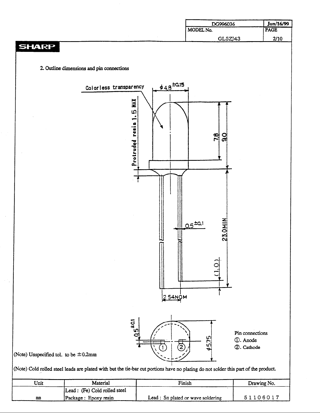
2. outline dimensions aad pin
co~ections
Colorless transparency
\
Pin COMectiOns
0. Anode
0. cathode
rote) Unspecif!ed tol. to be ~0.2mm
rote) Cold rolled steel leads are plated with but the tie-bar cut portions have no plating do not solder this part of the product.
. .
unit
Material
Finish
Drawing No.
Lead : (Fe) Cold rolled steel
mm
Package : Epoxy resin
Lead : Sn plated or wave soldering
51106017
Page 4
MODEL No.
DG996036
Jun/16/%
PAGE
3.
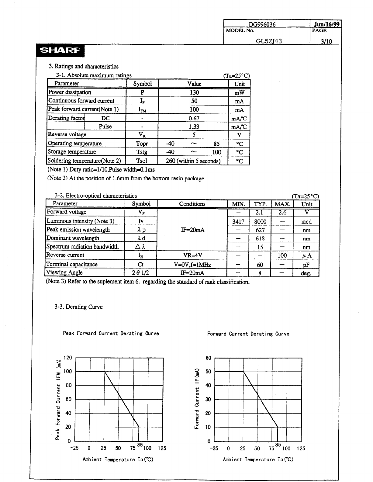
Ratings and characteristics
(Note 1) Duty ratio=l/lO,Pulse width=Qlms
(Note 2) At the position of 1.6mm from the bottom resin package
GL5ZJ43
3/10
(Note 3) Refer to the suplement item 6. regarding the standard of rank classification.
3-3. Derating Curve
Peak Forward Current Derating Curve
120
a
s
e 100
g 80
z
2 60
-0
5 40
2
,” 20
m
d
0’ ’
-25 0 25 50 75 ‘?iO 125
Ambient Temperature Ta(W Ambient Temperature Ta (%I
I I
I
Forward Current Derating Curve
60
-25 0 25 50 7585
100 125
Page 5

Peak Forward Current vs. Duty Ratio
10
l/100 l/10
Duty Raito DR
1 10
3-4. Characteristics Diagram&p) (Note 1)
MODEL No.
I
DG996036
GL5ZJ43
Jud16/9!3
PAGE
4/10
I
Forward Current vs.Forward Voltage
loo
0. 1
1 1.2 1.4 1.6 1.8 2 2.2 2.4 2.6
Forward Voltage VFOJ)
Relative Luminous Intensity vs. Frorard Voltap~
1000
5
.-
100
t
G
10
(Ta=25"C)
(Ta+X'C)
:
O-
EE
J
A
:
.-
c,
5
2
Relative Luminous Intensity
vs. Ambient Temperature
1000
Iiii”“iiiitlltrll I I I I
l-00
10
-40 -20 0 20 40 60 80
-60
Ambient Temprature TarC)_
( I F=2OmN
I I I I I I
100 120
>”
.-
0. 1
z
G
p:
0. 01
0. 1 1 10
Forward Current IFhA)
(Note 1) Above characteristic data are typical data and not a guarantteed data.
100
Page 6

4. Reliability
The reliability of products shall be satisfied with items listed below.
MODEL No.
DG996036
Jun/16/99
PAGE
GL5ZJ43 5110
Ll. Test items and test conditions
Test items Test conditions
Solderability
soldering
temperature
Mechanical shock
Variable frequency
23025°C. 5s
Prior disposition : Dip in rosin flux
260t5”C. 5s
15 0OOm/s*, 0.5ms.
3times f iX+Y&Z direction
2OOm/s*, 100 to 2 0OO to lOOH&weep for 4min.
vibration ,4timesffX,*Yfi direction
Terminal strength
(Tension)
Terminal strength
(Bending)
Weight: 1ON. Ss/each terminal
Weight:SN,O” + 9O” + O”* -90” + 0”
/each terminal
Temperature cycling -4O”c(3Omin)~+10O”c(3Omin),30 cycles
High temp. and high
humidity storage
Ta=+6O”c, 9O%RH, t=100Oh
igh temperature storage Ta=lO0”C, t=10OOh
Cordidence level: 90%
Samples (n) LTPD
Defective (C) (%)
n=ll. C=O 20
n=ll, C=O 20
n=ll, C=O 20
n=ll, C=O 20
n=ll. C=O 20
n=ll, C=O 20
n=22, C=O
10
n=22, C=O 10
n=22, C=O 10
ow temperature storage Ta=40”C, t=lOO0h
Operation life
Ta=25@C, IrMAX, t=lOOOh *3
4-2. Measurement items and Failure judgement criteria *l
Measurement Symbol Failure judgement criteria *2
Forward voltage
Reverse current
VF
IR
Luminous intensity Iv
Iv > The first stage value X 2.0 or The first stage value X 0.5 > Iv
v, > U.S.L. x 1.2
IR > U.S.L. x 2.0
z Solderability : Solder shall be adhere at the area of 95% or more of dipped portion.
% Terminal strength : Package is not destroyed, and terminal is not slack.
* 1: Measuring condition is in accordance with specification.
*2: U.S.L. is shown by Upper Specification Limit.
*3: IF MAX.is shown by forward current of absolute maximum ratings.
n=22. C=O 10
n=22, C=O 10
Page 7

MODEL, No.
5. Incoming inspection
5-l. Applied standard : IS0 2859-1
5-2. Sampling method and level : A single sampling plannormal inspection level lI
: AQL Major defect : 0.065%
Minor defect : 0.4%
5-3. Test items. iudaement criteria and classifica of defect
DG996036
GL5ZJ43
Jlln/16/99
PAGE
6110
No.
1
2
Test items judgement criteria
DiscoMection
Position of Cutting off
rim
Not emit light
Different from dimension Major defect
3 Reverse terminal Different from dimension
4
Outline
5 characteristics
dimensions
Not satisfy outline specification
Over the limit value of specification at V,, Ia, and Iv
6 Cut off the rim Exceed -0.2mm
White pint : Exceed d 0.3nun (on top view)
7
Foreign substance Black point : Exceed 4 0.3mm (on top view)
String form: Exceed 3.Omm (on top view)
8
9
10
material for scattering
Scratch
Void Exceed 4 0.3mm (on top view)
Uneven density of
Exceed 9 0.3mm or O.lmm x l&run (on top view) Minor defect
Extremely uneven density
classifica of defer
11 Unbalanced center Exceed +&25mm from package center
12
Insertion position of
.3
Burr Exceed +0.2mm againstprovided dimension
terminal
Insertion position of terminal
5-4. Test items the surface is be applied for flat type, judgement criteria and classifica of defect
No. Test items judgement criteria
14
Chapped the surface
15
Hollow the surface
The surface chapped is striking for see the lamp top
The surface hollow is striking for see the lamp top
classifica of defec
Minor defect
Page 8

6. Supplement
6-l. Packing
6-l-l. Inner package
Put 25Opcs the same luminous intensity rank products into pack and put following label by pack.
Product weight : 0.28g (One ProducfTyp.)
(Indication label sample)
SHIPMENT TABLE
PART No.
ClUANTITY
LOT No. KA99B19
GL5ZJ43
250
+ Model number
+ Quantity of products
4- Lot number *
Cl-0 t - Luminous intensity rank
SHARP’
MADE IN JAPAN
dominant wavelength rank
+ Production country
0 Production plant code(to be indicated alphabetically)
@ support code
@ Year of production(the last two figures of the year)
@ Month of production
(to be indicated alphabetically with January corresponding to A)
@ Date of production(Ol-3 1)
DG996036
MODEL No.
GL5ZJ43
*o cl clclclclo
- ---
0 0 O@ 0
Jun/16/99
PAGE
7/10
6-l-2. Outer package
Put 8 packs (the same luminous intensity rank) into outer package.
(approximately 670g per one outer package)
6-l-3. Outer package out line dimension
Width : 14Omm. Depth : 225mm, Hight : 90mm
6-2Luminous intensim rank (Note 1)
Rank
Q
R
S
T
4
Luminous intensity
3417 - 6657
4920 - 9586
7085 - 13803
10203 - ( 19877)
unit Condition
mcd +2OmA
tTa=25aC 1
.--- -- ~_
(Note 1) Tolerance:*15%
In regard to luminous intensity , the following ranking shall be carried out.
However the quantity of each rank shall not be pre scribed.
In case of the distribution of the luminous intensity shift to high, at that
point new upper rank is prescribed and lower rank is delete.
6-3.Dominant wavelength rank (Note 2)
Rank Dominant wavelength
T 613.5 - 617.0
I
unit
(Ta=25”C)
Condition
U 616.0 - 619.5
V 618.5 - 622.0 run 1~2Om4
W 621.0 - 624.5
X 623.5 - 627.0
I--
INote 2) The condition of measurement : The measurement of the light emission from the front side of lamp.
This rank value
is the setting value of when that classifies it the rank and be not a guarantee value.
Also I shall not ask the delivery ratio of each rank.
Page 9

64 Environment
641. Ozonosphere destructive chemicals.
(1) The device doesn’t contain following substance.
(2) The device doesn’t have a production line whose process requires following substance.
Restricted part: CFCsJlalonestCCL,Trichloroethane(Methych
642. Bromic non-burning materials
The device doesn’t contain bromic non-burning materia.Ls(PBBOs~BBs)
DG!N6036 Junt16l99
MODEL No. PAGE
GL5ZJ43
8110
Page 10

7.
pncaurions for use
7 - 1. Lead forming method
Avoid forming a lead pin with the lead pin base as
a fulcrum:be sure to hold a lead pin firmly when
forming. Lead pins should be formed before soldering.
7 - 2. Notice of installation
7-2-l installation on a P W B
Vhen mounting an LED lamp on a PVB,do not apply
physical stress to the lead pins.
*The lead pin pitch should match the PYB pin-hole
pitch:absolutely avoid widening or narrowing
the lead pins.
l
Vhen positioning an LED lamp,basically employ
an LED with tie-bar cut or use a spacer.
7-2-2 Vhen an LED 1 is mounted directly on a P W B
If the bottom face of an LED lamp is mounted
directly on single-sided Pm, the base of the
lead pins may be subjected to physical stress
due to PIB warpcutting or clinching of lead
pins. Prior to use, be sure to check that no
disconnection inside of the resin or damage to
resin etc.,is found-When an LED lamp is mounted
on a double-sided PYB,the heat during soldering
affects the resin;therefore,keep the LED lamp
more that 1.61~s~ afloat above the PVB.
7-2-3 Installation using a holder
During an LED lamp positioning,when a holder is
used,a holder should be designed not to subject
lead pins to any undue stress.
(Note)Pay attention to the thermal expansion coefficient
of the material used for the holder.Since the
holder expands and contracts due to preheat and
soldering heat,mechanical stress may be applied to
the lead pins, resulting in disconnection.
7-2-4 Installation to the case
Do not fix part C with adhesives when fixed to the
case as shown in Figure-A hole of the case should
be designed not to subject the inside of resin
to any undue stress.
MODEL, No.
I
IX996036
GL5ZJ43
Junl16/99
PAGE
9110
NG
Good
Page 11

7 - 3. Soldering Conditions
’ Solder the lead pins under the following conditions
Type of S oldering
1. Manual soldering
2. Wave soldering
3. Auto soldering
29%+5”c. within 3 seconds
26O”ck5”c, within 5 seconds
Preheating 70°C to 8O”c, within 30 seconds
Conditions
Soldering 245”c+5”c, within 5 seconds
(Note) Avoid dipping resin into soldering bath
Avoid applying stress to lead pins while they are heated. For example ,
when the LED lamp is moved with the heat applied to the lead pins during
manual soldering or solder repair,disconnection may occur.
DG996036 JunllWW
MODEL No. PAGE
GL5ZJ43
lo/lo
7 - 4. For cleaning
( 1) Solvent cleaning : Solvent temperature 45°C or less
Immersion for 3 min or less
(2 > Ultrasonic cleaning : The effect to device by ultrasonic cleaning differs
by cleaning bath size,ultrasonic power
output,cleaning time,PW size or device mounting
condition etc. Please test it in actual using condition
and confirm that doesn’t occur any defect before starting
the ultrasonic cleaning.
( 3 > Applicable solvent : Ethyl alcohol, Yethyl alcohol, Isopropyl alcohol
In case when the other solvent is used,there are cases that
the packaging resin is eroded. Please use the other solvent
after thorough confirmation is performed in actual using condition.
 Loading...