

Page 1
ELM334
1234876
5
Garage Doorman
Description
5
4
7
2
6
3
Features
The ELM334 is a handy circuit for remotely
monitoring the position of your garage door. A twowire interface is all that is needed to convey the
position of the door to two remotely located LEDs,
and to also provide control for an electric opener if
desired.
This circuit continually monitors the state of two
position sensing switches, representing the fully
open and fully closed positions of the door. After
suitable debouncing, the states of these switches
are used to vary the polarity of the two signal wires,
resulting in either the red (open) or green (closed)
LED turning on. When the door is in neither position
(moving), the LEDs rapidly alternate between the
two colours.
If desired, circuitry to detect a short between the
two LED wires can be added and used to operate a
control output. If the door is equipped with a
standard electric opener, this control signal can be
used to operate the door. Refer to the Example
Application section for further details.
Applications
• Low power CMOS design
• Wide supply range - 3.0 to 5.5 volt operation
• Simultaneous monitoring of three inputs
• Fully debounced inputs
• Two wire interface
• Stuck button protection on the control output
• Control function is an optional addition
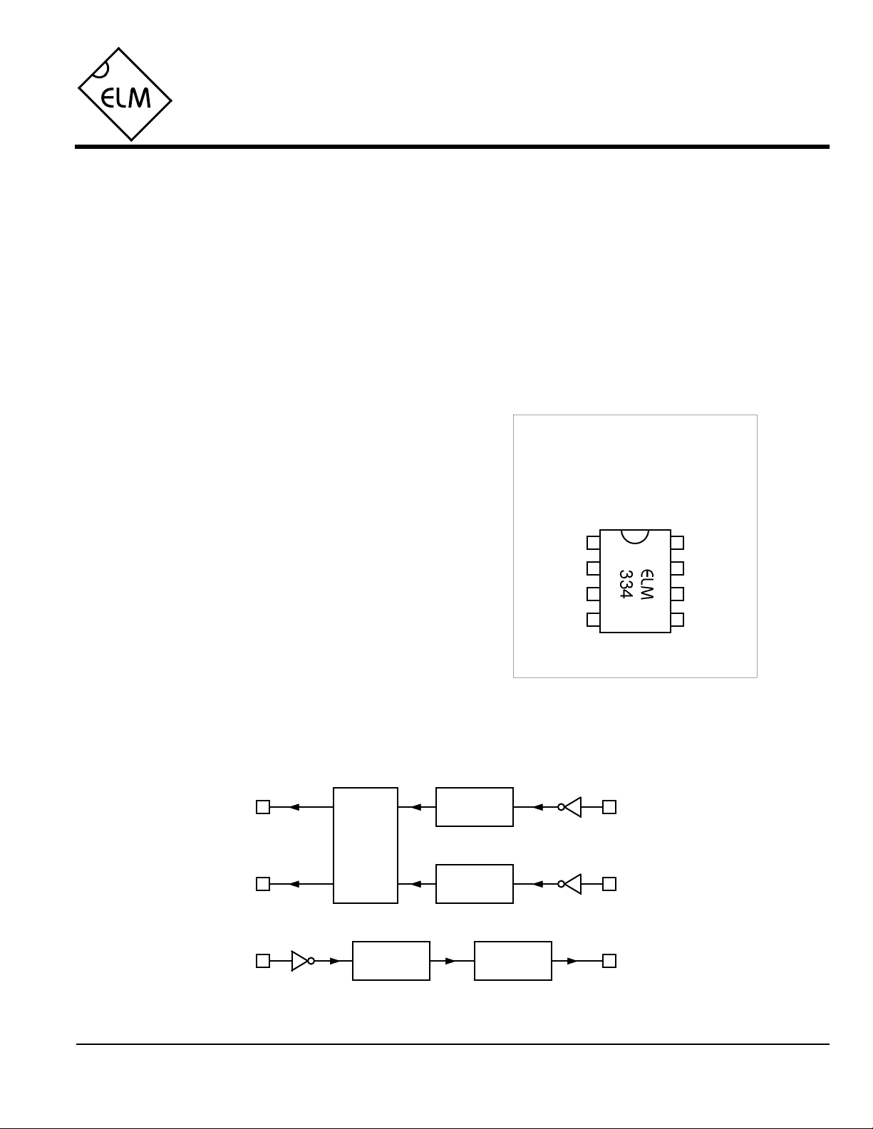
Connection Diagram
PDIP and SOIC
(top view)
VDD VSS
RLED
GLED
OpenSw
ClosedSw
ControlPB
• Garage door monitoring and control
• Remote signalling and acknowledgement
Block Diagram
RLED
PB
ELM334DSB
Elm Electronics – Circuits for the Hobbyist
Debounce
Timers
Drive
Logic
Debounce
Timers
Debounce
Timers
Output
Limitter
< http://www.elmelectronics.com/ >
OpenSw
ClosedSwGLED
Control
1 of 4
Page 2

ELM334
Pin Descriptions
VDD (pin 1)
This pin is the positive supply pin, and should
always be the most positive point in the circuit.
Internal circuitry connected to this pin is used to
provide power on reset of the microprocessor, so
an external reset signal is not required. Refer to
the Electrical Characteristics section for further
information.
RLED (pin 2), and GLED (pin 3)
These two pins are for driving a red and a green
LED through a current limiting resistance.
Typically the LED used will be a dual type, that
appears white if not energized, red if energized
in one polarity, and green if the polarity is
reversed. Alternatively, two discrete LEDs could
be wired ‘back-to-back’. During powerup, the red
LED will be lit for 0.5sec, followed by the green
for 0.5sec, and then the circuit will alternate
between the two for a further 0.5sec.
PB (pin 4)
A momentary low level signal on this pin will
cause the control output to go high, after
approximately 25msec delay due to the internal
debounce circuitry. If unused, this pin should be
connected to VDD.
Control (pin 5)
This output goes to an active high level (VDD), in
response to a valid low level on pin 4. The
duration of the output will be the same as the
input, to a maximum of 500ms. At this point, the
circuit will assume that the button is ‘stuck’, or
there has been a wiring fault, and it will turn the
output off. The state of the RLED and the GLED
lines is not updated if the circuit thinks that the
pushbutton is being pressed.
ClosedSw (pin 6), and OpenSw (pin 7)
These two inputs are for monitoring the position
of the door. This is normally done by connecting
magnetic reed type switches between each of
these pins and VSS, with the two switches
mounted at the extreme positions of the door
travel. When fully open, only the OpenSw input
will be at a logic low level (switch closed), and
when fully closed, only the ClosedSw input will
be low. Both switches simultaneously open or
closed will cause the LEDs to alternately flash
red and green as a warning (or as feedback that
the door is moving). Internal circuitry provides a
nominal 0.5sec debounce period on both inputs.
VSS (pin 8)
Circuit common is connected to this pin. This is
the most negative point in the circuit.
Ordering Information
All rights reserved. Copyright ©1999 Elm Electronics.
Every effort is made to verify the accuracy of information provided in this document, but no representation or warranty can be
given and no liability assumed by Elm Electronics with respect to the accuracy and/or use of any products or information
described in this document. Elm Electronics will not be responsible for any patent infringements arising from the use of these
products or information, and does not authorize or warrant the use of any Elm Electronics product in life support devices and/or
systems. Elm Electronics reserves the right to make changes to the device(s) described in this document in order to improve
reliability, function, or design.
ELM334DSB
These integrated circuits are available in either the 300 mil plastic DIP format, or in the 200 mil SOIC surface
mount type of package. To order, add the appropriate suffix to the part number:
300 mil Plastic DIP............................... ELM334P 200 mil SOIC.....................................ELM334SM
Elm Electronics – Circuits for the Hobbyist
< http://www.elmelectronics.com/ >
2 of 4
Page 3

ELM334
Absolute Maximum Ratings
Stresses beyond those listed here will likely damage
the device. These values are given as a design
guideline only. The ability to operate to these levels
is neither inferred nor recommended.
Storage Temperature.......................-65°C to +150°C
Note:
Ambient Temperature with
Power Applied....................................-40°C to +85°C
Voltage on VDD with respect to VSS............0 to +7.5V
Voltage on any other pin with
respect to VSS........................... -0.6V to (VDD + 0.6V)
Electrical Characteristics
All values are for operation at 25°C and a 5V supply, unless otherwise noted. For further information, refer to note 1 below.
Characteristic Minimum Typical Maximum ConditionsUnits
Supply Voltage, VDD 3.0 5.0 5.5 V
VDD rate of rise 0.05 V/ms
Average Supply Current, IDD 1.0 2.4 mA
Debounce Period msec25
Pushbutton
Position Switches
msec500
see note 2
VDD = 5V, see note 3
Maximum Control Pulse Width msec500
Input low voltage VSS 0.15 VDD V
Input high voltage VDD V0.85 VDD
Output low voltage 0.6 V
Output high voltage VVDD - 0.7
Notes:
1. This integrated circuit is produced with a Microchip Technology Inc.’s PIC12C5XX as the core embedded
microcontroller. For further device specifications, and possibly clarification of those given, please refer to the
appropriate Microchip documentation.
2. This spec must be met in order to ensure that a correct power on reset occurs. It is quite easily achieved
using most common types of supplies, but may be violated if one uses a slowly varying supply voltage, as
may be obtained through direct connection to solar cells, or some charge pump circuits.
3. Integrated circuit only. Does not include any LED or drive currents.
4. This is the maximum output pulse width, if the pushbutton input remains active. If the pushbutton is released
prior to this time, the output will simply follow the input.
see note 4
Current (sink) = 8.7mA
Current (source) = 5.4mA
ELM334DSB
Elm Electronics – Circuits for the Hobbyist
3 of 4
< http://www.elmelectronics.com/ >
Page 4

Example Application
ELM334
1234876
5
Figure 1 shows the ELM334 in a typical circuit that
provides both monitoring and control. An unregulated
12V supply is used to drive the relay coil and is stepped
down to 5V for the IC. The regulation isn’t essential for
this type of circuit, but it is a convenient means to
reduce the 12V, while providing some filtering from
motor noise, etc.
Operation of the LED portion of this circuit is
straight-forward. The position sensing magnetic reed
switches are connected to the 5.1KΩ pullup resistors in
order to provide a full logic swing input to the ELM334
as they operate. The 2.2KΩ series resistors provide
some protection for the chip as the wires to the switches
are likely to be lengthy, and susceptible to induced
voltages and currents. After processing, the appropriate
voltages appear at pins 2 and 3, driving the LEDs
through the 150Ω current limiting resistors.
+12V
+5V
0.1µF
78L05
0.1µF
The control portion of the circuit may appear to be a
little odd-looking at first. To understand its operation,
note that one of the two driven LEDs is always on,
whether flashing or solid. Due to the connection of the
two NPN transistors then, one of the NPNs is always
biased on, keeping the PNP on, and pin 4 of the
ELM334 at 5V. When the pushbutton is pressed, the
LED circuit is shorted out, and neither NPN can
conduct. The PNP thus shuts off, and pin 4 of the IC
drops to 0V, its active level. With the PB input active, a
high level is output at pin 5, causing the relay to pick up.
Although this circuit was designed for a very
specific purpose, there are likely to be many other
applications that it can be adapted to. Monitoring
thermostats perhaps, or water levels…
+5V
5.1KΩ
2.2KΩ
‘open’
+5V
green
red
Remote LEDs
& Pushbutton Control
10KΩ
10KΩ
2N3904
10KΩ
2N3904
150Ω
150Ω
+5V
+5V
1N4001
2N3906
5.1KΩ
5.1KΩ
Figure 1. Typical Monitoring and Control Circuit
ELM334DSB Elm Electronics – Circuits for the Hobbyist
< http://www.elmelectronics.com/ >
2.2KΩ
5.1KΩ
2.2KΩ
‘closed’
+12V
12V Relay
To the
motor
control
2N3904
4 of 4
 Loading...