

Page 1
DLZ-5
8
1
2
3
4
5
6
7
9
10
11
12
13
14
15
16
05008
. . . engineered solutions for the transient environment™
APPLICATIONS
✔ Military & Aerospace Data Line Protection
✔ RS-232 & RS-423
✔ Microprocessor Based Equipment
✔ Multiple Data & Power Bus Line Protection
IEC COMPATIBILITY (EN61000-4)
✔ 61000-4-2 (ESD): Air - 15kV, Contact - 8kV
✔ 61000-4-4 (EFT): 40A - 5/50ns
✔ 61000-4-5 (Surge): 24A, 8/20µs - Level 2 (Line-Gnd) & Level 3 (Line-Line)
FEATURES
✔ MIL-STD-461 Compatible
✔ 1300 Watts Peak Pulse Power per Line (tp=8/20µs)
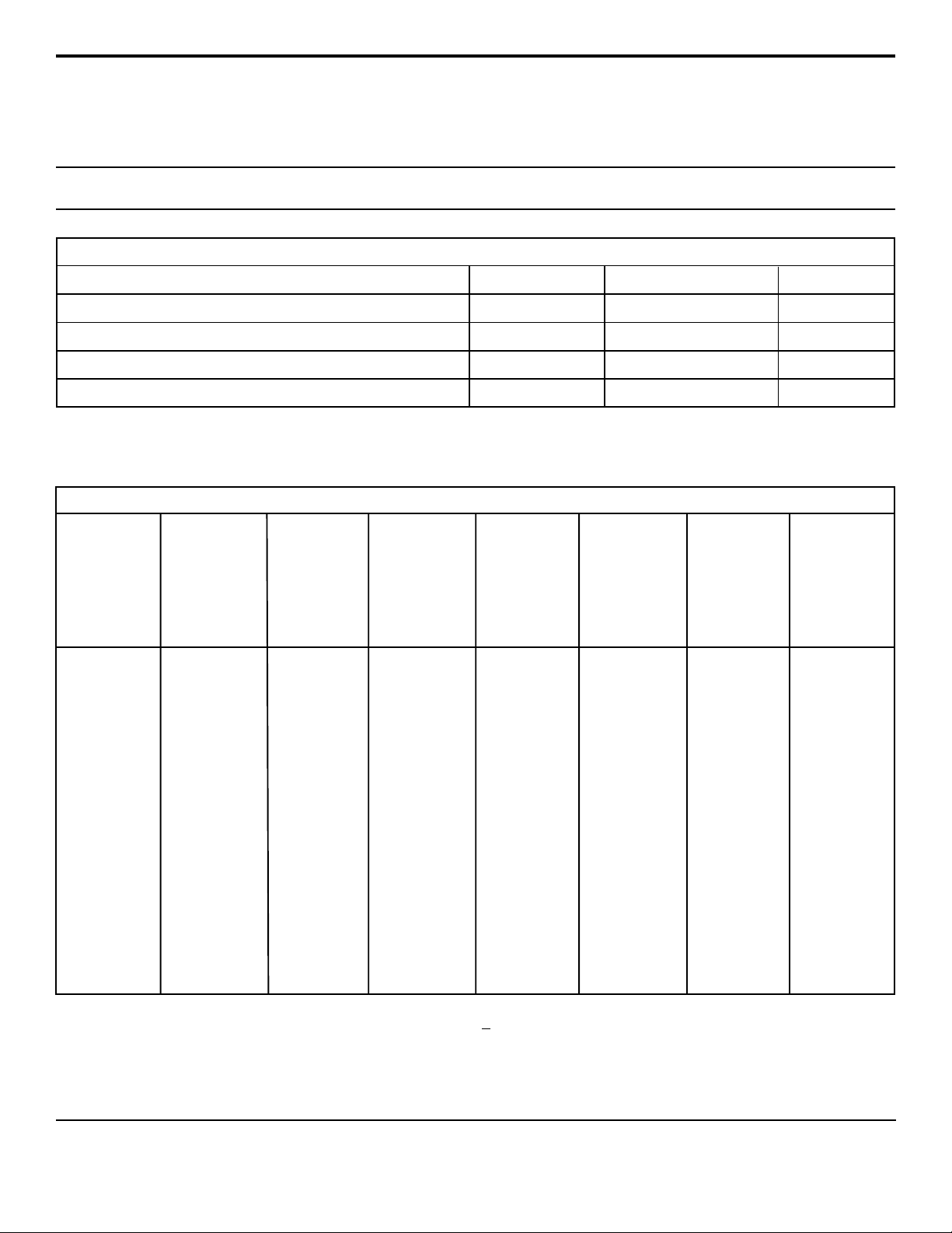
✔ Unidirectional & Bidirectional Configurations
✔ ESD Protection > 40 kilovolts
✔ Internal Common Ground
✔ Available in Multiple Voltage Types: 5.0V to 30.0V
✔ ✔
✔
PROTECTS UP TO 15 LINES
✔ ✔
thru
DLZ-30CA
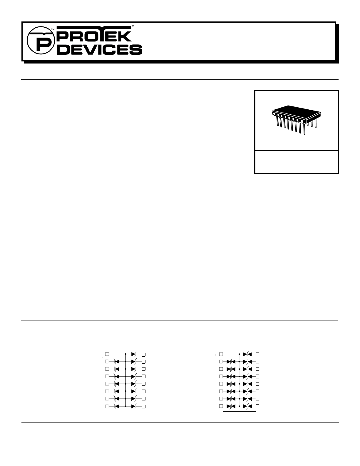
STANDARD TVS ARRAYS
16 PIN CERAMIC
MECHANICAL CHARACTERISTICS
✔ Ceramic 16 Pin Hermetically Sealed Package
✔ Weight 3.2 grams (Approximate)
✔ Flammability rating UL 94V-0
✔ Marking: Date Code, Logo, Part Number & Pin One Defined By Flag on Lead
✔ Screened for Military Requirments in Accordance with MIL-PRF-19500
- Standard screening consists of 100% JANTX equivalent level testing per
MIL-PRF-19500
- For ordering these options, use the following suffix:
H1 - 100% JANTX level screening
H2 - 100% JANTX level screening with Group B testing
✔ Screened to DESC Drawing #94029 (Bidirectional) & #94030 (Unidirectional)
CIRCUIT DIAGRAMS
UNIDIRECTIONAL
1
2
3
4
5
6
7
8
16
15
14
13
12
11
10
9
BIDIRECTIONAL
1
www.protekdevices.com05008.R4 6/02
Page 2
DEVICE CHARACTERISTICS
MAXIMUM RATINGS @ 25°C Unless Otherwise Specified
DLZ-5
thru
DLZ-30CA
PARAMETER
Peak Pulse Power (tp = 8/20µs) - See Figure 1
Operating Temperature
Storage Temperature
Forward Surge Rating (1/20 seconds) - Unidirectional Only Amps10I
SYMBOL VALUE
P
PP
T
J
T
STG
F
1300
-55°C to 150°C
ELECTRICAL CHARACTERISTICS PER LINE @ 25°C Unless Otherwise Specified
PA RT
NUMBER
(Note 1)
DLZ-5
DLZ-5A
DLZ-12
DLZ-12A
DLZ-17
DLZ-17A
DLZ-24
DLZ-24A
DLZ-30
DLZ-30A
RATED
STAND-OFF
VOLTAGE
V
WM
VOLTS
5.0
5.0
12.0
12.0
17.0
17.0
24.0
24.0
30.0
30.0
MINIMUM
BREAKDOWN
VOLTAGE
@ 1mA
V
(BR)
VOLTS
6.0
6.0
13.3
13.3
19.2
19.2
26.7
26.7
33.3
33.3
MAXIMUM
CLAMPING
VOLTAGE
(See Fig. 2)
@ I
= 1 A
P
V
C
VOLTS
10.2
9.5
21.1
19.1
30.4
27.5
42.3
38.3
52.8
47.8
MAXIMUM
CLAMPING
VOLTAGE
(See Fig. 2)
@ 8/20µs
VC @ I
PP
18.1V @ 70A
19.2V @ 66A
28.0V @ 48A
33.0V @ 41A
37.4V @ 35A
40.0V @ 33A
50.5V @ 26A
62.4V @ 21A
62.9V @ 21A
60.0V @ 24A
MAXIMUM
LEAKAGE
CURRENT
@V
WM
I
D
µA
200
200
2
2
2
2
2
2
2
2
MAXIMUM
CAPACITANCE
@ 0V, 1 MHz
C
pF
880
880
440
440
330
330
275
275
220
220
UNITS
Watts
°C-55°C to 150°C
°C
TEMPERATURE
COEFFICIENT
OF V
(BR)
θV
(BR)
mV/°C
5
5
18
18
20
20
31
31
39
39
DLZ-8C
DLZ-13C
DLZ-13CA
DLZ-19C
DLZ-19CA
DLZ-30C
DLZ-30CA
Note 1: Part numbers with a “C” suffix are bidirectional devices, i.e., DLZ-8C.
05008.R4 6/02
8.0
13.0
13.0
19.0
19.0
30.0
30.0
8.5
14.4
14.4
21.6
21.6
33.3
33.3
13.4
22.8
20.6
34.2
31.0
52.8
47.8
2 www.protekdevices.com
29.0V @ 45A
31.0V @ 43A
34.0V @ 39A
40.5V @ 33A
47.6V @ 28A
68.7V @ 19A
62.5V @ 21A
10
440
4
4
4
4
4
4
385
385
275
275
165
165
9
18
18
24
24
39
39
Page 3

GRAPHS
DLZ-5
thru
DLZ-30CA
100,000
10,000
1000
- Peak Pulse Power - Watts
PP
P
100
0.1 1 10 100 1,000 10,000
PEAK PULSE POWER VS PULSE TIME
FIGURE 2
120
PP
100
80
60
40
- Peak Pulse Current - % of I
20
PP
I
0
0 5 10 15 20 25 30
PULSE WAVE FORM
t
f
Peak Value I
-t
e
td = t
t - Time - µs
PP
IPP/2
TEST
WAVEFORM
PARAMETERS
tf = 8µs
td = 20µs
FIGURE 1
1300W 8/20µs Waveform
td - Pulse Duration - µs
POWER DERATING CURVE
FIGURE 3
100
80
60
40
% Of Rated Power
20
0
0 25 50 75 100 125 150
T
- Lead Temperature - °C
L
Peak Pulse Power
8/20µs
Average Power
3 www.protekdevices.com05008.R4 6/02
Page 4

PACKAGE OUTLINE & DIMENSIONS
DLZ-5
thru
DLZ-30CA
A
Pin One Index
H
PACKAGE OUTLINE
B
E
IG
F
16 PIN CERAMIC DIP
C
DIMENSIONS
MILLIMETERS
D
DIM MIN MAX MIN MAX
A
B
C
D
E
F
G
H
I
NOTES:
1. Dimensions are exclusive of metal
burrs and solder protusions.
2. Package sealed with ceramic or metal lid.
22.72
11.43
-
7.36
-
4.19
2.42
0.33
0.88
23.48
12.19
4.87
7.84
-
-
2.66
0.57
1.12
INCHES
0.895
0.450
-
0.310
0.025 REF
0.165
0.095
0.023
0.035
0.925
0.480
0.192
0.290
- REF
-
0.105
0.013
0.045
06029 Rev 0 - 3/02
Protek Devices
2929 South Fair Lane, Tempe, AZ 85282
Tel: 602-431-8101 Fax: 602-431-2288
E-Mail: sales@protekdevices.com
Web Site: www.protekdevices.com
COPYRIGHT © ProTek Devices 2001
SPECIFICATIONS: ProTek reser ves the right to change the electrical and or mechanical characteristics described herein without notice (except JEDEC).
DESIGN CHANGES: ProTek reser ves the right to discontinue product lines without notice, and that the final judgement concerning selection and specifications is the buyer’s and that in furnishing engineering and
technical assistance, ProTek assumes no responsibility with respect to the selection or specifications of such products.
05008.R4 6/02
4 www.protekdevices.com
 Loading...