

Page 1

Magnetoresistance Element
For the availability of this product, please contact the sales office.
Description
The DM-106B is a highly sensitive magnetoresistance element composed of an evaporated
ferromagnetic alloy on a silicon substrate. (The
element can be used for automatic shut off of tape
recorders, as a contactless switch, and as a general
detector of rotational motion.)
Features
• Low power consumption 11 mW (Typ.)
VCC=5 V
• Low magnetic field and high sensitivity
80 mVp-p (Typ.)
VCC=5 V
H=8000 A/m
• High reliability
Ensured through silicon
Nitride protective filming
DM-106B
M-110 (Plastic)
Structure
Thin-film nickel-cobalt magnetic alloy on silicon
substrate
Absolute Maximum Ratings (Ta=25 °C)
• Supply voltage VCC 10 V
• Operating temperature Topr –40 to +100 °C
• Storage temperature Tstg –50 to +125 °C
Recommended Operating Supply voltage 5V
Electrical Characteristics (Ta=25 °C)
Item Symbol Condition Min. Typ. Max. Unit
Total resistance
Midpoint potential
Output voltage
RT
VC
VO
VCC=5 V , H=8000 A/m
Revoiving magnetic field
VCC=5 V , H=8000 A/m
Revoiving magnetic field
VCC=5 V , H=8000 A/m
Revoiving magnetic field
1.4
2.45
60
2.3
2.50
80
3.7
2.55
kΩ
V
mVp-p
Sony reserves the right to change products and specifications without prior notice. This information does not convey any license by
any implication or otherwise under any patents or other right. Application circuits shown, if any, are typical examples illustrating the
operation of the devices. Sony cannot assume responsibility for any problems arising out of the use of these circuits.
—1—
E60142D5X-TE
Page 2
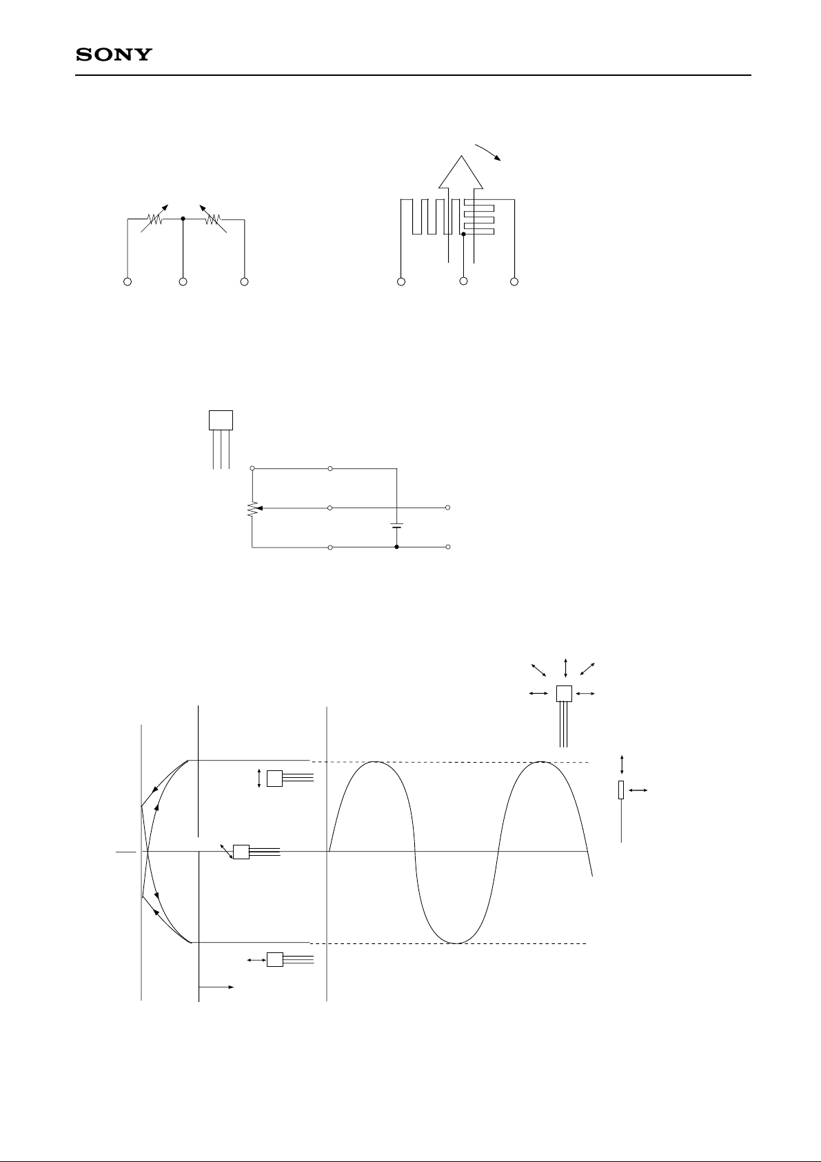
Equivalent Circuit
RA RB
1
23
Introduction
1. Power supplying pin output pin
106
B
H
θ
max
RA RB
1
2
min
3
DM-106B
RA : Resistance reduces as the
magnetic field revolves.
RB : Resistance increases as the
magnetic field revolves.
123
RA
RB
1
2
3
2. Sensitive direction vs. Midpoint potential
Midpoint potential
VCC
2
S
H
H
VCC
c
d
b
a
a
b
e
d
Direction of Magnetic-flux
Incidence
e
Sensitive
Non-sensitive
Direction of Magnetic-flux
Incidence
Useful Region
c
Changes occur to the output voltage at the saturation region
of V-H curve according to the direction of magnetic flux.
These changes provide for the operation.
• With one rotation of magnetic flux, signals for 2 periods are
obtained.
—2—
Page 3
Applications
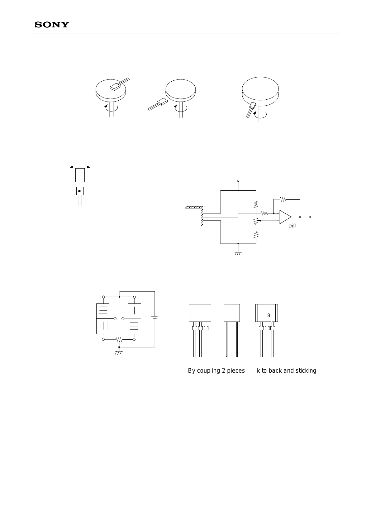
1. Detection of revolution
DM-106B
2. Position detecting
S
N
N
S
N
S
S
N
Circuits
VCC
N
S
N
S
N
S
r1
Differenntial
r2
Amplifier
3. Bridge Circuits
106
B
Output
106
B
By coupling 2 pieces back to back and sticking them
together in a gridge, the output voltage is doubled.
Notes on Application
• Execute the solder to the lead line within 10 seconds at a temperature below 260 °
• To Fix the ELEMENTS : When glue is used, DO NOT apply mechanical stress to the elements.
—3—
Page 4
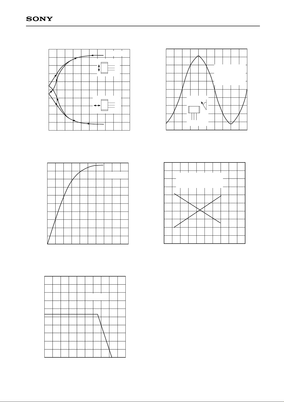
DM-106B
Midpoint potential vs. Magnetic field intensity
2.55
2.54
2.53
2.52
2.51
2.50
2.49
-Midpoint potential (V)
2.48
C
V
2.47
2.46
2.45
4000 120000
H-Revolving magnetic field intensity (A/m)
Output voltage vs. Magnetic field intensity
100
80
60
40
-Output voltage (mVp-p)
O
V
20
VCC=5V
106B
106B
8000 16000
VCC=5V
CC
GND V
CC
GND V
Midpoint potential vs. Direction of magnetic-flux incidence
2.55
2.54
2.53
2.52
2.51
1. VCC=5V
H=12000A/m
2. Output
3. GND
2.50
2.49
-Midpoint potential (V)
2.48
C
V
2.47
2.46
106B
3 2 1
H
θ
2.45
0
45 90 135 180
θ-Direction of magnetic-flux incidence (deg)
Total resistance, output voltage vs. Temperature
120
110
100
H=8000A/m
(Revolving magnetic field)
VCC=5V
RT
90
80
70
-Output voltage (mVp-p)
O
V
60
VO
225
3.0
2.5
2.0
-Total Resistance (kΩ)
T
R
0
4000 8000
0
H-Revolving magnetic field intensity (A/m)
5
4
3
2
-Input current (mA)
IN
I
1
0
—40
0 40 160
Ta-Ambient temperature (°C)
12000 16000
Derating Curve
VCC=10V
80 120
50
1.5
—50 —25 0 25 50 75 100 125 150
Ta-Ambient temperature (°C)
—4—
Page 5
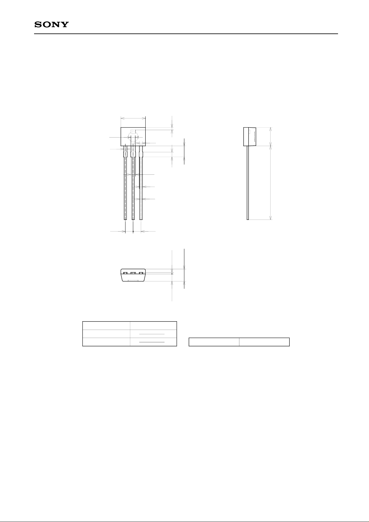
Package Outline Unit : mm
DM-106B
M-110
4.0 ± 0.2
0.4
0.7
0.5
0.5
1.8
0.8
0.6
0.4
1.271.27
0.8
0.25 ± 0.1
1.2 ± 0.1
2.0 ± 0.2
3.0 ± 0.2
12 MIN
SONY CODE
EIAJ CODE
JEDEC CODE
M-110
—5—
PACKAGE WEIGHT
0.09g
 Loading...