

Page 1
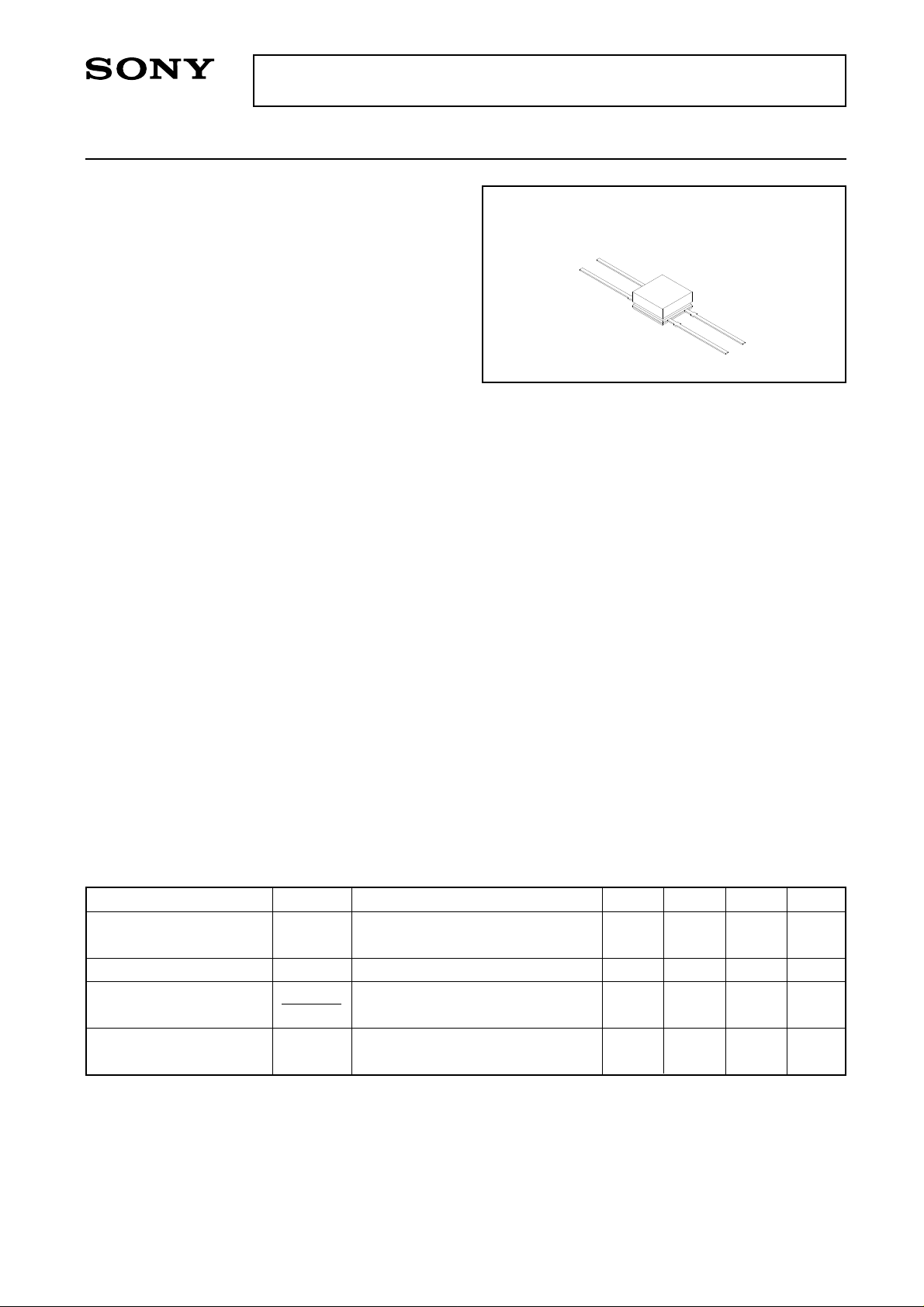
Magnetoresistance Element
For the availability of this product, please contact the sales office.
Description
DM-231 a magnetic sensor using magnetoresistance effect is composed of ferromagnetic material
deposited by evaporation on a silicon substrate. It is
suitable for angle of rotation detection.
Features
• Low magnetic field and high sensitivity: bridge type
stands for large output voltage
150 mVp-p (Min.) at VCC=5 V, H=14400 A/m
• Fitted with bias magnet: stable output.
• High reliability: Achieved through silicon nitride
protective film.
Structure
Ferromagnetic thin film circuit (With ferrite magnet)
DM-231
M-118 (Plastic)
Applications
• Non-contact angle of rotation detection.
• Contactless potentiometer.
Absolute Maximum Ratings (Ta=25 °C)
• Supply voltage VCC 10 V
• Storage temperature Tstg –30 to +100 °C
Recommended Operating Conditions
• Supply voltage VCC 5V
•Operating temperature Topr –20 to + 75 °C
Electrical Characteristics Ta=25 °C
Item Symbol Condition Min. Typ. Max. Unit
Output voltage
Midpoint potential
Midpoint potential
difference/Output voltage
Total resistance
VO
VA, VB
|VA-VB|
VO
RT
VCC=5 V , H=14400 A/m (Peak)
AC magnetic field θ =0 °
VCC=5 V , H=0 A/m
VCC=5 V , H=0 A/m
H=14400 A/m (Peak)
AC magnetic field θ =0 °
150
2.475
500 650
2.525
15
800
mVp-p
V
%
Ω
Sony reserves the right to change products and specifications without prior notice. This information does not convey any license by
any implication or otherwise under any patents or other right. Application circuits shown, if any, are typical examples illustrating the
operation of the devices. Sony cannot assume responsibility for any problems arising out of the use of these circuits.
—1—
E88Z12C5X-TE
Page 2
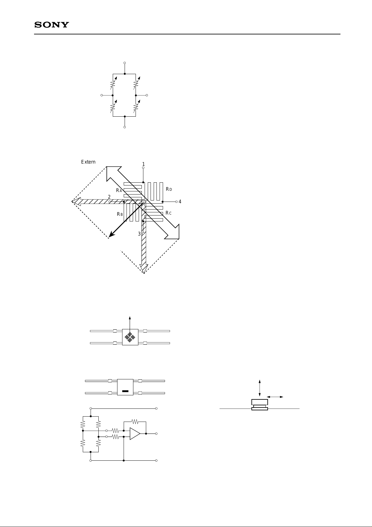
Equivalent Circuit
DM-231
1
CC
V
Basic Performance
1) Operation principle
External magnetic field H
Synthetic
magnetic field (a)
Bias magnetic field
H=14400A/m
VA
3
GND
RD
RC
4
B
V
RA
2
RB
Various resistances change according to the direction of
the combnied bias and external magnetic field.
1
¡) When the direction of the synthetic magnetic field is (a),
RA,RC : Maximum resistance
RB,RD : Minimum resistance
RA
2
R
B
3
RD
¡¡) When the direction of the synthetic magnetic field is (b),
4
RA,RC : Minimum resistance
RC
External magnetic field H
RB,RD : Maximum resistance
Synthetic magnetic field (b)
∗ Device internal structure
(Back of mark face)
Bias magnetic field
3
4
2
1
2) Power supply pin and output pin 3) Sensitivity direction
2
1
1
231
2
4
Differential amplifier
3
4
V
CC
Out put
The ferromagnetic magnetoresistance element differs
from the semiconductor magnetoresistance element and
hole element in that it responds only to the magnetic
Non-Sensitive
field within the element's surface. It is not sensitive to
3
GND
the magnetic field perpendicular to the element.
Sensitive
—2—
Page 3
Basic Application
Rotation angular detection
3
DM-231
S
N
4
2
1
Out put
Differential amplifier
Out put
–90°
Handling precautions
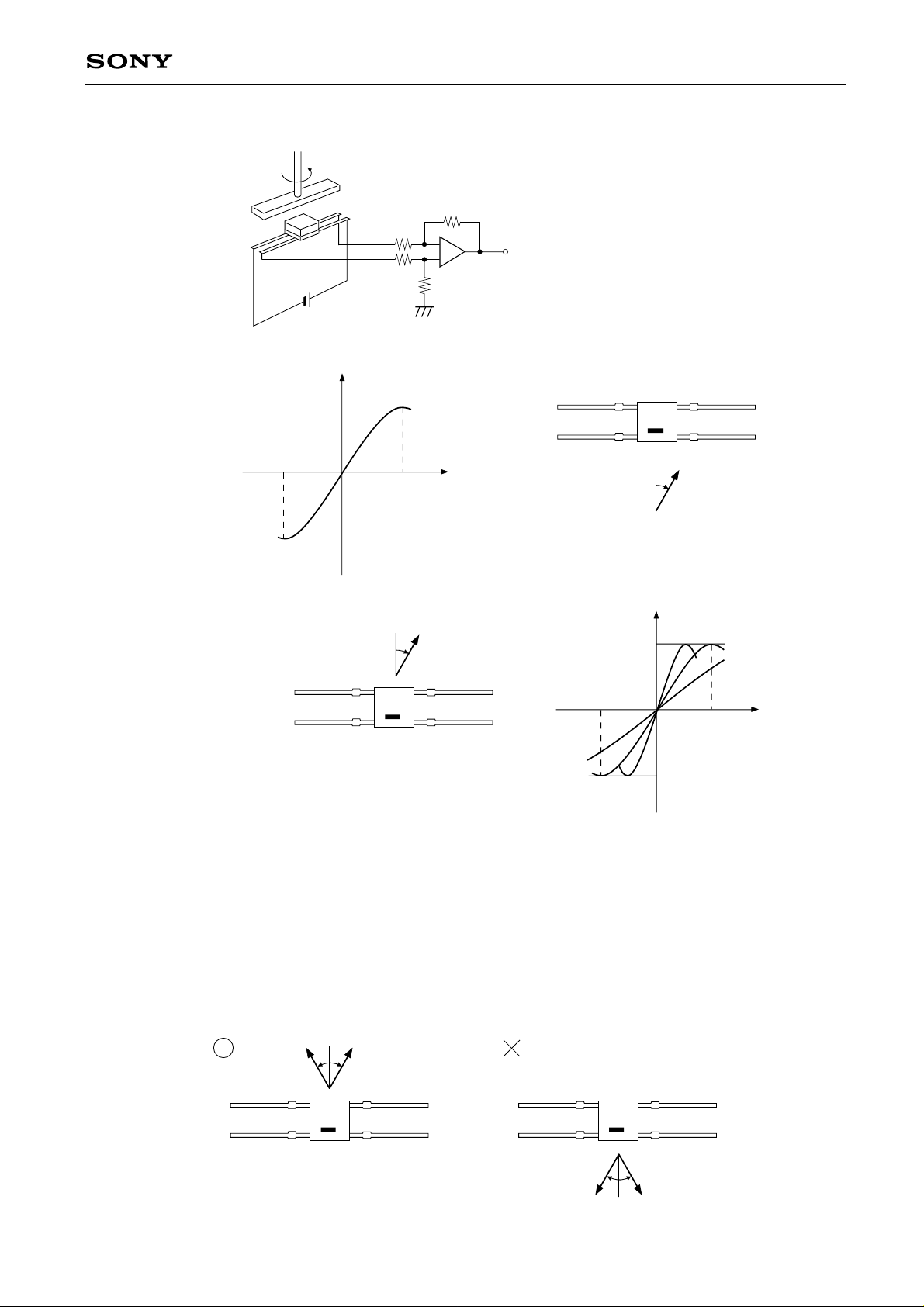
1) Most suitable magnetic
field intensity
When the external magnetic
field is at H=14400A/m,
rotation angle can be
detected most effectively.
H=14400A/m
0°
90°
θ
231
Magnetic field
angle θ
H
–90°
231
Out put
H
θ
Magnetic field angle θ
H>14400A/m
H=14400A/m
H<14400A/m
90°
0°
Magnetic field
angle θ
Whe the external magnetic field H<14400A/m, output voltage shrinks.
When the external magnetic field H>14400A/m, the detection angle range shrinks.
Whe the external magnetic field H<14400A/m, the detection angle range becomes larger. In regions other
than -90° to +90°, the magnetic field combined with the bias magnetic field, shrinks down, which is not
advisable. Also, when the range to be detected is smaller than -90° to +90° it is more advantageous to turn to
H>14400A/m.
2) External magnetic field direction
With regards to the bias magnetic field, usage at other than ±90° should be avoided. That causes a decrease
in the combined magnetic field intensity, that is not recommended.
HH
231 231
11
HH
—3—
Page 4
DM-231
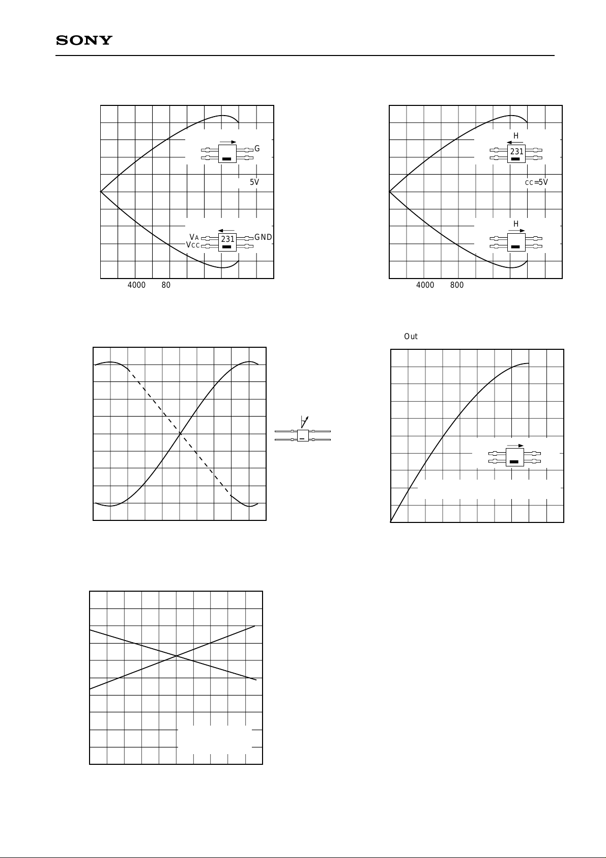
Midpoint potential vs. Magnetic field Intensi ty (1)
2.54
A
V
2.52
VCC
2.50
2.48
A
V
VCC
2.46
-Midpoint potential (V)
A
V
0
4000 8000 12000 16000
H-Magnetic field intensity (Oe)
Midpoint potential vs. Magnetic field direction
2.54
H
231
VCC=5V
H
231
GND
GND
Midpoint potential vs. Magnetic field Intensity (2)
2.54
2.52
VCC
2.50
-Midpoint potential (V)
B
2.48
V
VCC
2.46
0
4000 8000 12000 16000
H-Magnetic field intensity (Oe)
Output voltage vs. Magnetic field intensity
200
H
231
VCC=5V
H
231
GND
V
B
GND
B
V
2.52
2.50
-Midpoint potential (V)
B
2.48
, V
A
V
2.46
–45–90
θ-Magnetic field direction (deg)
Temperature characteristics
200
150
VA
H
θ
VA
V
231
CC
GND
VB
VCC=5V
H=14400A/m
VB
0
45 90
150
100
Vo-Output voltage (mVp-p)
50
0
H: Peak intensity of AC magnetic field
4000 8000 12000 16000
VA
VCC
VCC=5V
H
231
GND
B
V
H-Magnetic field intensity (Oe)
800
T
R
700
600
VO
100
Vo-Output voltage (mVp-p)
50
—20
0204060
Ta-Ambient temperature (°C)
H=14400A/m
AC Magnetic field
VCC=5V
80
500
400
-Total resistance (Ω)
T
R
—4—
Page 5
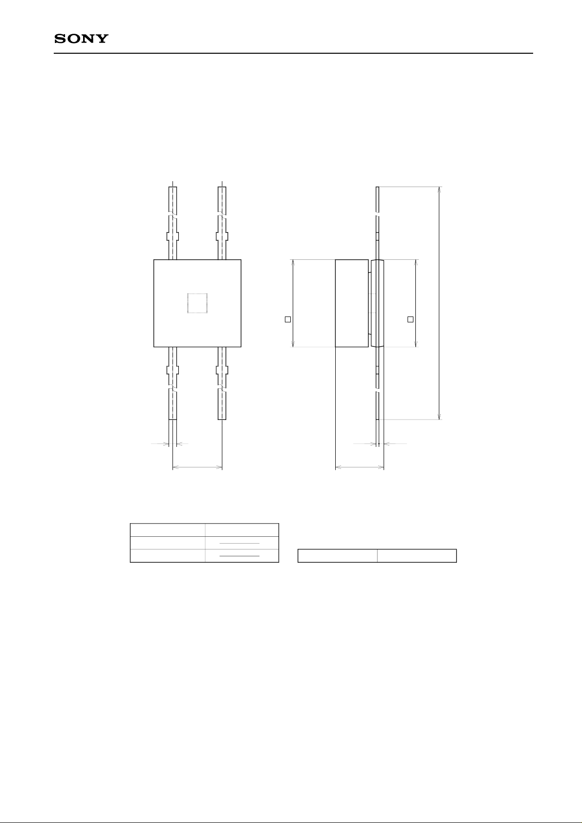
Package Outline Unit : mm
M-118
4.5 ± 0.1
+ 0.4
4.5 – 0.1
DM-231
22.0 ± 0.3
0.4
SONY CODE
EIAJ CODE
JEDEC CODE
2.54
M-118
2.5 MAX
PACKAGE WEIGHT
0.250.15
0.2g
—5—
 Loading...